EP1415726A2 - Vorrichtung zur Vorbereitung der Strömung an der Lippe eines Vorhangbeschichtungssystems zur Verbesserung der Gleichmässigkeit des Flüssigkeitsvorhangs - Google Patents
Vorrichtung zur Vorbereitung der Strömung an der Lippe eines Vorhangbeschichtungssystems zur Verbesserung der Gleichmässigkeit des Flüssigkeitsvorhangs Download PDFInfo
- Publication number
- EP1415726A2 EP1415726A2 EP20030078297 EP03078297A EP1415726A2 EP 1415726 A2 EP1415726 A2 EP 1415726A2 EP 20030078297 EP20030078297 EP 20030078297 EP 03078297 A EP03078297 A EP 03078297A EP 1415726 A2 EP1415726 A2 EP 1415726A2
- Authority
- EP
- European Patent Office
- Prior art keywords
- surface portion
- lip
- ledge
- slide die
- curtain
- Prior art date
- Legal status (The legal status is an assumption and is not a legal conclusion. Google has not performed a legal analysis and makes no representation as to the accuracy of the status listed.)
- Withdrawn
Links
- 239000007788 liquid Substances 0.000 title claims abstract description 43
- 238000000034 method Methods 0.000 title claims abstract description 24
- 238000002360 preparation method Methods 0.000 title description 28
- 238000007766 curtain coating Methods 0.000 title description 9
- 238000000576 coating method Methods 0.000 claims abstract description 28
- 239000011248 coating agent Substances 0.000 claims abstract description 27
- 239000000203 mixture Substances 0.000 claims abstract description 21
- 230000005484 gravity Effects 0.000 claims abstract description 12
- 230000007423 decrease Effects 0.000 claims description 2
- 239000008199 coating composition Substances 0.000 description 60
- 238000009736 wetting Methods 0.000 description 45
- 238000004140 cleaning Methods 0.000 description 12
- 230000015572 biosynthetic process Effects 0.000 description 9
- 230000003287 optical effect Effects 0.000 description 8
- 238000012360 testing method Methods 0.000 description 8
- 238000005259 measurement Methods 0.000 description 7
- 239000002904 solvent Substances 0.000 description 7
- 238000011010 flushing procedure Methods 0.000 description 6
- 230000001788 irregular Effects 0.000 description 6
- 230000007704 transition Effects 0.000 description 6
- 238000011109 contamination Methods 0.000 description 5
- 239000002131 composite material Substances 0.000 description 4
- 239000002002 slurry Substances 0.000 description 4
- 239000004094 surface-active agent Substances 0.000 description 4
- OKTJSMMVPCPJKN-UHFFFAOYSA-N Carbon Chemical compound [C] OKTJSMMVPCPJKN-UHFFFAOYSA-N 0.000 description 3
- 229910052799 carbon Inorganic materials 0.000 description 3
- 230000003749 cleanliness Effects 0.000 description 2
- 239000000356 contaminant Substances 0.000 description 2
- 238000012423 maintenance Methods 0.000 description 2
- 239000000463 material Substances 0.000 description 2
- 239000000123 paper Substances 0.000 description 2
- 230000036961 partial effect Effects 0.000 description 2
- 238000000926 separation method Methods 0.000 description 2
- XLYOFNOQVPJJNP-UHFFFAOYSA-N water Substances O XLYOFNOQVPJJNP-UHFFFAOYSA-N 0.000 description 2
- 108010010803 Gelatin Proteins 0.000 description 1
- 229920000663 Hydroxyethyl cellulose Polymers 0.000 description 1
- 239000004354 Hydroxyethyl cellulose Substances 0.000 description 1
- 230000009471 action Effects 0.000 description 1
- 235000013405 beer Nutrition 0.000 description 1
- 239000007844 bleaching agent Substances 0.000 description 1
- 239000006229 carbon black Substances 0.000 description 1
- 230000008859 change Effects 0.000 description 1
- 230000000739 chaotic effect Effects 0.000 description 1
- 239000003795 chemical substances by application Substances 0.000 description 1
- 239000012459 cleaning agent Substances 0.000 description 1
- 238000010276 construction Methods 0.000 description 1
- 239000003599 detergent Substances 0.000 description 1
- 238000009826 distribution Methods 0.000 description 1
- 230000009977 dual effect Effects 0.000 description 1
- 239000004744 fabric Substances 0.000 description 1
- 229920000159 gelatin Polymers 0.000 description 1
- 239000008273 gelatin Substances 0.000 description 1
- 235000019322 gelatine Nutrition 0.000 description 1
- 235000011852 gelatine desserts Nutrition 0.000 description 1
- 238000009499 grossing Methods 0.000 description 1
- 230000002706 hydrostatic effect Effects 0.000 description 1
- 235000019447 hydroxyethyl cellulose Nutrition 0.000 description 1
- 238000009434 installation Methods 0.000 description 1
- 230000031700 light absorption Effects 0.000 description 1
- 238000004519 manufacturing process Methods 0.000 description 1
- 230000007246 mechanism Effects 0.000 description 1
- 239000002184 metal Substances 0.000 description 1
- 238000000424 optical density measurement Methods 0.000 description 1
- 238000005457 optimization Methods 0.000 description 1
- 239000004033 plastic Substances 0.000 description 1
- 229920000642 polymer Polymers 0.000 description 1
- 238000004445 quantitative analysis Methods 0.000 description 1
- 238000011084 recovery Methods 0.000 description 1
- 239000000126 substance Substances 0.000 description 1
- 230000036962 time dependent Effects 0.000 description 1
- 238000012546 transfer Methods 0.000 description 1
- 238000013519 translation Methods 0.000 description 1
- 239000002699 waste material Substances 0.000 description 1
Images



Classifications
-
- B—PERFORMING OPERATIONS; TRANSPORTING
- B05—SPRAYING OR ATOMISING IN GENERAL; APPLYING FLUENT MATERIALS TO SURFACES, IN GENERAL
- B05C—APPARATUS FOR APPLYING FLUENT MATERIALS TO SURFACES, IN GENERAL
- B05C5/00—Apparatus in which liquid or other fluent material is projected, poured or allowed to flow on to the surface of the work
- B05C5/007—Slide-hopper coaters, i.e. apparatus in which the liquid or other fluent material flows freely on an inclined surface before contacting the work
- B05C5/008—Slide-hopper curtain coaters
-
- G—PHYSICS
- G03—PHOTOGRAPHY; CINEMATOGRAPHY; ANALOGOUS TECHNIQUES USING WAVES OTHER THAN OPTICAL WAVES; ELECTROGRAPHY; HOLOGRAPHY
- G03C—PHOTOSENSITIVE MATERIALS FOR PHOTOGRAPHIC PURPOSES; PHOTOGRAPHIC PROCESSES, e.g. CINE, X-RAY, COLOUR, STEREO-PHOTOGRAPHIC PROCESSES; AUXILIARY PROCESSES IN PHOTOGRAPHY
- G03C1/00—Photosensitive materials
- G03C1/74—Applying photosensitive compositions to the base; Drying processes therefor
-
- B—PERFORMING OPERATIONS; TRANSPORTING
- B05—SPRAYING OR ATOMISING IN GENERAL; APPLYING FLUENT MATERIALS TO SURFACES, IN GENERAL
- B05C—APPARATUS FOR APPLYING FLUENT MATERIALS TO SURFACES, IN GENERAL
- B05C9/00—Apparatus or plant for applying liquid or other fluent material to surfaces by means not covered by any preceding group, or in which the means of applying the liquid or other fluent material is not important
- B05C9/06—Apparatus or plant for applying liquid or other fluent material to surfaces by means not covered by any preceding group, or in which the means of applying the liquid or other fluent material is not important for applying two different liquids or other fluent materials, or the same liquid or other fluent material twice, to the same side of the work
-
- G—PHYSICS
- G03—PHOTOGRAPHY; CINEMATOGRAPHY; ANALOGOUS TECHNIQUES USING WAVES OTHER THAN OPTICAL WAVES; ELECTROGRAPHY; HOLOGRAPHY
- G03C—PHOTOSENSITIVE MATERIALS FOR PHOTOGRAPHIC PURPOSES; PHOTOGRAPHIC PROCESSES, e.g. CINE, X-RAY, COLOUR, STEREO-PHOTOGRAPHIC PROCESSES; AUXILIARY PROCESSES IN PHOTOGRAPHY
- G03C1/00—Photosensitive materials
- G03C1/74—Applying photosensitive compositions to the base; Drying processes therefor
- G03C2001/7433—Curtain coating
-
- Y—GENERAL TAGGING OF NEW TECHNOLOGICAL DEVELOPMENTS; GENERAL TAGGING OF CROSS-SECTIONAL TECHNOLOGIES SPANNING OVER SEVERAL SECTIONS OF THE IPC; TECHNICAL SUBJECTS COVERED BY FORMER USPC CROSS-REFERENCE ART COLLECTIONS [XRACs] AND DIGESTS
- Y10—TECHNICAL SUBJECTS COVERED BY FORMER USPC
- Y10S—TECHNICAL SUBJECTS COVERED BY FORMER USPC CROSS-REFERENCE ART COLLECTIONS [XRACs] AND DIGESTS
- Y10S118/00—Coating apparatus
- Y10S118/04—Curtain coater
Definitions
- the present invention relates generally to a method and apparatus for coating objects, such as a moving web, by curtain coating. More particularly, the invention relates to an improved curtain coating method and apparatus for the manufacture of sheet goods, including film and paper.
- a moving receiving surface is coated by the impingement of a free-falling curtain of liquid coating composition.
- the curtain may be a single coating composition or a composite of several layers of distinct coating compositions, such as described in U.S. Patent. No. 3,508,947 (Hughes), commonly assigned.
- the coating-receiving surface can be any surface that can be passed through a curtain.
- the receiving surface can be the surface of a discrete object but is typically the surface of a continuous web of paper, plastic, metal, or cloth.
- a curtain that is a composite of several layers of distinct coating compositions can be formed by a slide die with multiple elements for distributing coating compositions as layers and with an inclined slide surface on which the layers flow by gravity.
- FIG. 1 there is shown generally a curtain coating system comprising two slots 2,3 from which two layers flow superimposed on an inclined flow surface 4.
- the system includes a lip area/region 5 from which the coating composition leaves the system along a front surface 6, forming a curtain.
- the curtain then impinges onto a surface, for example a moving support.
- the coating composition falls from a horizontal lip to the coating-receiving surface over a vertical distance between about 2 cm and about 30 cm.
- the coating composition in the curtain is freely falling and accelerates by gravity.
- each edge guide comprises parallel dual wires, flushing means near the lip of the slide die, and suction means near the coating-receiving surface, as disclosed in U.S. Patent Nos. 5,328,726 ( Reiter ), 5,725,910 ( Devine ), 5,763,013 ( Devine ), or 5,976,251 ( Devine ), all commonly assigned.
- a wetting line on the lip where the curtain forms.
- a front surface of the lip is part of the slide surface over which the composite layer of coating composition flows.
- a wetting line on a partially wetted back surface of the lip may be substantially vertical, and the back surface of the lip may form a sharp angle, such as 30°, with the front surface of the lip.
- the back surface of the lip is typically upwardly inclined to direct flow into the curtain.
- the tip of the lip may be sharp or chamfered.
- An example of a lip is disclosed in U.S. Patent No. 5,462,598 ( Servant ), commonly assigned, wherein the wetting line is not positioned at the tip of the lip, but rather at some small distance, less than about 1 mm, along the back surface of the lip.
- the wetting line is straight and horizontal, but this is typically not the outcome of starting flow and forming a curtain. More likely, the position of the wetting line varies along the lip and may be jagged in some areas. It is known that an irregular wetting line can cause objectionable non-uniformities in the coated layers of highly sensitive products. These non-uniformities in the coated layers usually continue in the coating direction substantially unchanged and are typically referred to as "streaks". An irregular wetting line can also give rise to stationary waves in the curtain which can also result in streaks in the coated layers.
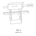
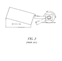
- Gruszczynski Another known apparatus intended to correct wetting line shape is disclosed in U.S. Patent No. 6,346,299 ( Gruszczynski ), commonly assigned, and is shown in Figure 3.
- Gruszczynski employs a movable trough positioned in proximity to the lip. The coating composition flowing on the slide is intercepted by the trough and fills the trough. The level of coating composition wets the back surface of the lip beyond the natural position of the wetting line. The ends of the trough are preferably open to prevent or limit the overflowing of the edges of the trough. The movable trough is then extracted. This apparatus avoids contact with the lip, however, a translation or rotary motion of the trough is required.
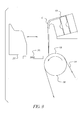
- a preparation pan with edge walls to minimize splashing and splattering is disclosed in U.S. Patent No. 5,338,359 ( Conroy ), commonly assigned, and is shown in Figure 4.
- the preparation pan includes flushed edge walls spaced from edge guides to stabilize partial curtains outside the preparation pan. While this apparatus has achieved a certain degree of success, the pan is intricate, and its use alone does not ensure a straight wetting line on the lip. Additional remedies are referenced in Baumlin or Gruszczynski.
- An object of the present invention is to provide a method and apparatus for generating a straight wetting line on the back surface of a lip of a slide die for curtain coating.
- Another object of the present invention is to provide such an apparatus and method for wetting line formation that does not require physical contact with the lip.
- a further object of the present invention is to provide such an apparatus and method for wetting line formation that can be stationary and can utilize the positioning mechanism for the slide die.
- Yet a further object of the present invention to provide such an apparatus and method for wetting line formation that does not result in spillage, splashing and/or contamination.
- a still further object of the present invention to provide such an apparatus and method for wetting line formation wherein the curtain is left in full contact with the edge guides.
- Yet a still further object of the present invention to provide such an apparatus and method for wetting line formation that can additionally be employed in cleaning the lip.
- an apparatus for improving the uniformity of a liquid curtain in a coating system comprising a lip of a slide die wherein the lip includes a front surface on which a liquid composition flows by gravity.
- the apparatus comprises a ledge and positioning means.
- the ledge includes a first, second, and third surface portion.
- the first surface portion is disposed intermediate the second and third surface portions.
- the first surface portion is substantially horizontal.
- the second surface portion is contiguous with the first surface portion and upwardly inclined.
- the third surface portion is contiguous with the first surface portion and downwardly inclined away from the first and second surface portions.
- the positioning means positions the ledge and lip relative to each other (1) in a first orientation wherein the lip is disposed proximate the first surface portion whereby the liquid composition flows from the slide die onto the first surface portion, and (2) in a second orientation wherein the lip and the ledge are spaced from each other whereby the liquid composition forms a vertical liquid curtain in free fall.
- a method for improving the uniformity of a liquid curtain in a coating system comprising a lip of a slide die wherein the lip includes a front surface on which a liquid composition flows by gravity.
- the method comprises the steps of: (1) providing a ledge having a first, second, and third surface portion wherein the first surface portion is disposed intermediate the second and third surface portions, the first surface portion is substantially horizontal, the second surface portion is contiguous with the first surface portion and upwardly inclined, and the third surface portion is contiguous with the first surface portion and downwardly inclined away from the first and second surface portions; (2) supplying the liquid composition to the slide die; and (3) positioning the ledge and lip relative to each other in a first orientation wherein the lip is disposed proximate the first surface portion whereby the liquid composition flows from the slide die onto the first surface portion.
- the curtain coating system comprises a feeding system from which flows the curtain composition comprising at least one layer.
- dies and weirs can be employed to form free-falling liquid curtains.
- a slide die 10 includes multiple die elements 11 for laterally distributing coating compositions to form a curtain that is a composite of several layers of distinct coating composition. Layers of the coating composition flow from slots onto a slide surface 12 that is downwardly inclined so that the layers flow by gravity. Slide die 10 terminates at a substantially horizontal lip 13. That is, substantially horizontal across the width of the die, wherein the width is referenced as a direction transverse to the direction of the moving support (i.e., coating width).
- a curtain C of freely falling coating composition extends from lip 13 to a coating-receiving surface 15 over a vertical distance, preferably between about 2 cm and about 30 cm.
- the coating composition in curtain C accelerates by gravity.
- Coating-receiving surface 15 can be any surface that can be passed through curtain C such as discrete three-dimensional objects or continuous webs.
- a web 14 with coating-receiving surface 15 is preferably supported through the zone of curtain impingement by a precision backing roller 16.
- Lip 13 includes a front surface 17 that is part of slide surface 12, and a back surface 18 that is not part of slide surface 12 and partially wetted.
- a wetting line 19 disposed on back surface 18 may be irregular in shape as a result of transients in starting the flow of coating composition.
- Wetting-line irregularities can produce streaks in the coating that must be removed as waste if sufficiently severe.
- a streak is a widthwise variation in coating uniformity continuing indefinitely and substantially unchanged in the direction of coating.
- Wetting-line irregularities can also cause stationary waves in the curtain that result in streaks.
- the coating non-uniformities associated with stationary waves in the curtain become increasingly severe as total flow rate is increased. Therefore, the non-uniformities typically manifest as coating speed is increased or as more layers are coated simultaneously, which are steps frequently taken for improved productivity. Accordingly, there exists a need for determining an effective and practical method/system to prevent wetting-line irregularities.
- Ledge 20 is substantially parallel to lip 13 of slide die 10 across the width of the die.
- Ledge 20 includes a first surface portion 21, a second surface portion 22, and a third surface portion 23, wherein first surface portion 21 is disposed intermediate second surface portion 22 and third surface portion 23.
- a first surface portion 21 of ledge 20 is substantially horizontal though preferably pitched slightly downward towards slide die 10. That is, ledge 20 is slightly downwardly inclined in the direction toward slide die 10.
- the pitch/incline of first surface portion 21 of ledge 20 is preferably in the range of about 0° to about 5°, from horizontal, depicted as ⁇ from the x-axis shown in Figure 7.
- Second surface portion 22 is contiguous with first surface portion 21 and is configured to extend upward and away from slide die 10.
- Third surface portion 23 is contiguous with first surface portion 21 and is configured to be pitched steeply downward. Third surface portion 23 is closer to slide die 10 than second surface portion 22.
- a pitch of third surface portion 23 is preferably in the range of about 45° to about 90° from horizontal.
- the transitions between the three surface portions 21, 22, 23 are preferably smooth and rounded rather than distinct edges so to promote flow and drainage.
- first surface portion 21 is typically disposed just above first surface portion 21 as best shown in Figure 6.
- Figure 6 shows a cross-sectional view preparation ledge 20 showing the position of lip 13 for advancing the wetting line beyond its natural position.
- Such a gap between lip 13 and first surface portion 21 ranges from about 0.5 mm to about 5 mm, and is typically about 2 mm.
- the coating composition flows from slide die 12 to first surface portion 21 and passes through the gap and onto third surface portion 23.
- Second surface portion 22 blocks the flow of the coating composition in the other direction. Indeed, slide surface 12, first surface portion 21, and second surface portion 22 form a reservoir 24 that fills partially.
- sink means 25 can include any type of collecting device for the collection of coating composition for disposal or recovery.
- a layer of the coating composition disposed on first surface portion 21 adjacent/behind lip 13 is thick because of the substantially horizontal orientation of first surface portion 21.
- the coating composition partially wets back surface 18 of lip 13.
- Surface tension also drives the partial wetting.
- the height of a wetting line above a tip of lip 13 is preferably between about 1 and a few millimeters. Accordingly, the proximity of lip 13 to preparation ledge 20 causes wetting line 19 to advance upward along back surface 18 beyond its natural position for coating. Wetting line 19 then recedes to its natural position upon the separation of lip 13 and preparation ledge 20 for coating.
- the receding coating composition results in a straight wetting line.
- the position of lip 13 be such that the third surface portion 23 intercepts the coating composition after a short fall and guides it to sink means 25 as best depicted in Figure 7.
- Figure 7 shows a side cross-sectional view of preparation ledge 20 showing a preferred position of lip 13 when coating compositions are first brought to slide die 10.
- a solvent for the coating composition or a cleaning solution is delivered to the elements of slide die 10 to remove all the coating composition.
- a suitable solvent is water
- cleaning agents include chemicals such as surfactants, detergents, and bleach.
- lip 13 it is advantageous for lip 13 to be positioned over first surface portion 21 as shown in Figure 6 so that the solvent or cleaning solution partially wets back surface 18 of lip 13.
- Contaminants on back surface 18 of lip 13, including solidified coating composition can cause wetting line irregularities. Therefore, back surface 18 is preferably clean, and the preparation ledge used together with an effective solvent or cleaning solution helps to soften and/or remove contaminants and prevent further contamination.
- slide die 10 is substantially empty and dry when the coating compositions are first delivered. In this situation, expensive coating composition is not wasted displacing some other liquid, such as a cleaning liquid, from the die.
- Delivering coating composition to a dry slide die is known to be more prone to forming wetting line irregularities than to a die initially filled with solvent or cleaning solution. Therefore, the present invention is particularly advantageous for startup from a dry slide die.
- a flushing liquid such as a solvent or cleaning solution, can be delivered to the surfaces of ledge 20 after use to clean them.
- flushing liquid may, for example, be delivered to second surface portion 22 through a slit, holes, or the like from a distribution cavity within the body of ledge 20. The flushing liquid would subsequently flow over the first and third surface portions of ledge 20 and into sink means 25 by gravity.
- a particularly advantageous method is to employ the positioning means for the slide die and to maintain the preparation ledge stationary.
- the slide die moves by a precision linear positioning device, such as a linear motor. Therefore, it is efficient to stationarily position ledge 20 and use an existing positioning means to position lip 13 with respect to ledge 20.
- ledge 20 can be moved if desired. It is noted that the manner in which the relative position of lip 13 and preparation ledge 20 is achieved is not believed to be critical to the function.
- Curtain C may not form along the edge guides when slide die 10 and preparation ledge 20 are separated in preparation for coating. More particularly, when the curtain is not in contact with the edge guides, the curtain narrows as it falls due to surface tension. Curtain formation along the edge guides depends upon many factors including the effectiveness of the particular edge guides in use, the flow rate of coating composition, and the value of surface tension. Although an operator can draw the curtain down the edge guides by one of several manual methods, automatic attachment of the curtain to the edge guides is preferable.
- two side plates 27 of preparation ledge 20 can attach the curtain to the edge guides as the preparation ledge and slide die separate, as best shown in Figure 8. These side plates need only be of a sufficient thickness for mechanical stability.
- side plates 27 extend beyond third surface portion 23 toward slide die 10 by a projecting length that gradually increases as elevation decreases.
- the projecting length is small or negligible where first 2 and third 23 surface portions meet and increases at the rate of about 1 centimeter for every 10 centimeters of vertical drop.
- a linear increase is effective, but Applicant notes that other continuously increasing profiles can also be effective.
- Side plates 27 preferably project far enough that the curtain remains in contact with them after it detaches from third surface portion 23 of preparation ledge 20. Thereafter, side plates 27 maintain curtain width and gradually transfer the curtain to the edge guides as the ledge and slide die separate, as depicted in Figure 8.
- the distance between the side plates and edge guides is a few millimeters.
- the side plates extend along the entire length of the edge guides to ensure the attachment of the curtain, but depending upon many factors, the curtain may form even if the side plates extend downward some lesser distance.
- Flushing the preparation ledge with a solvent or cleaning liquid after use is not essential but can be advantageous for cleanliness.
- the flushing liquid can be introduced onto second surface portion 22 and flow by gravity along the second, first, and third surface portions to sink means 25. Smoothing the transitions between first 21 and second 22 surface portions and first 21 and third 23 surface portions also promotes cleanliness by facilitating the drainage of liquids.
- Coating width may change to accommodate different products. Attaching extensions with the same cross section can increase the width of the preparation ledge. Replacing the ledge with one of different width is another option because the cost of a ledge is modest. Various methods of attachment that allow precise and rapid replacement are known.
- the present invention is generally directed to providing a ledge that is substantially parallel to the lip across the width of the die.
- the ledge has a first surface portion that is substantially horizontal.
- the ledge has a second surface portion contiguous with the first surface portion that is inclined upwardly and away from the slide die to block flow.
- the ledge also has a third surface portion contiguous with the first surface portion that is closer to the slide die than the second surface portion and that is downwardly inclined to remove coating composition by gravity.
- the ledge has side plates projecting toward the slide die that draw the curtain down the edge guides as the ledge and slide die are separated for the commencement of coating.
- the ledge can as well be advantageously used when cleaning solution is delivered to the slide die. In that case the position of the lip is slightly above the first surface portion for an extended period of time so that cleaning solution wets the back surface of the lip beyond the normal position of the wetting line.
- Test liquids of aqueous hydroxyethyl cellulose polymer with surfactant were prepared at viscosities of 0.2, 0.4, 0.7 and 1.8 poise. Measurements were made over a broad range of flow rates.
- the first surface portion had an inclination of 2°
- the second surface portion had an inclination of 45°
- the third surface portion had an inclination of 75°
- the lip was positioned 2 mm above the first surface portion just beyond the transition.
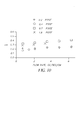
- Figure 10 shows a plot of measurements of the height of the wetting line above the tip of the lip for various flow rates and viscosities. More particularly, Figure 10 shows a plot of the measurements showing how the wetting line advances above the tip of the lip by 0.2 - 0.4 cm, a distance exceeding its equilibrium position of no more than about 1 mm. The advance is somewhat greater the higher the flow rate and the higher the viscosity, but one gap is suitable for a broad range of conditions.
- a curtain was formed using a five-element slide die.
- the first surface portion had an inclination of 2°; the second surface portion had an inclination of 45°; the third surface portion had an initial inclination of 75° for 3 cm and a final inclination of 90°; the transition between the first and second surface portions had a radius of 3 mm; and the transition between the first and third surface portions had a radius of 3 mm.
- the coating composition was aqueous gelatin with viscosity 0.4 poise.
- the coating composition delivered to the lowermost element of the slide die had a flow rate of 0.30 cc/sec per cm of curtain width; this coating composition contained surfactant and a slurry of carbon black to provide optical density in the curtain.
- the coating composition delivered to the adjacent two elements of the die had a flow rate of 1.07 cc/sec per cm of width.
- the coating composition delivered to the uppermost two elements of the die had a flow rate of 1.07 cc/sec per cm of width and contained surfactant.
- the total flow rate in the curtain was therefore 2.44 cc/s per cm of width.
- the coating composition from the lowermost element of the slide die wets the back surface of the lip, and so confining the carbon slurry to that portion of the coating composition accentuates the streaks from wetting-line irregularities.
- An optical densitometer mounted to a motor-driven positioning slide was used to measure the optical density of the curtain across 81 cm of the total curtain width of 135 cm. A measurement of optical density was acquired every 0.08 cm. The optical density measurement is related to the thickness of the layer of coating composition containing the carbon slurry through Beer's law of light absorption. A streak caused by an irregular wetting line is of the order of a centimeter in width, and the longer variations in layer thickness caused by mechanical tolerances of the die element are unrelated to wetting-line shape. Time-dependent variations in layer thickness also occur as a result of slightly unsteady flow. Sources of unsteadiness include pumps, mechanical vibrations of the slide die, and unsteady ambient airflow.
- the data were averaged to reduce the variations in optical density unrelated to wetting-line streaks.
- a moving average of a density trace was computed from data covering 1.27 cm (17 consecutive measurement points). This averaged data was subtracted from the original data and the root-mean-square (rms) was computed to obtain an estimate of the amplitude of the streaks from wetting-line irregularities. After formation of the curtain, the average rms value was 0.213% with a standard deviation of 0.047%. After straightening the wetting line, the average rms value was 0.130% with a standard deviation of 0.017%, and this value indicated a streak-free condition. The two optical density traces taken for each condition gave nearly the same values.
- Wetting-line irregularities also cause slight deformations of the surfaces of the curtain that experienced observers can see in reflected light of low-incidence. This subjective method was used to verify the effectiveness of the ledge at eliminating wetting-line irregularities. The subjective and quantitative methods gave consistent results.
- coating composition was delivered to a die that had been drained. With the lip in position over the first surface portion and gapped at 0.08 cm, coating composition was initially delivered to the lowermost die element and then to the remaining die elements in order. After the trough and die were separated, an rms value of 0.12 corresponding to a straight wetting line was obtained. Similarly, a value of 0.13 was obtained for a gap of 0.23 cm.
- coating composition was brought to the die with the lip above the third surface portion.
- coating composition containing the carbon slurry was delivered to the lowermost element of the die for a period of five minutes before coating composition was delivered to the remaining elements in order.
- the flow rate from the bottom element is insufficient to form a curtain; instead the coating composition falls from the lip as regularly spaced streamers that promote an irregular wetting line.
- the ledge and slide die were separated for enough time to obtain optical density traces. The lip and first surface portion were then positioned to straighten the wetting line. Upon separation of the ledge and slide die, optical density traces were again obtained.
- the rms value was determined before and after the action of the ledge.
- rms values of 0.24 and 0.13 were obtained before and after the wetting line was straightened, respectively.
- values of 0.29 and 0.13 were obtained.
- values of 0.18 and 0.13 were obtained at a gap of 0.15 cm and values of 0.20 and 0.13 at a gap of 0.23 cm.
Landscapes
- Chemical & Material Sciences (AREA)
- Engineering & Computer Science (AREA)
- Materials Engineering (AREA)
- Physics & Mathematics (AREA)
- General Physics & Mathematics (AREA)
- Coating Apparatus (AREA)
- Application Of Or Painting With Fluid Materials (AREA)
Applications Claiming Priority (2)
| Application Number | Priority Date | Filing Date | Title |
|---|---|---|---|
| US286031 | 2002-11-01 | ||
| US10/286,031 US6924006B2 (en) | 2002-11-01 | 2002-11-01 | Lip preparation apparatus and method for improving the uniformity of a liquid curtain in a curtain coating system |
Publications (2)
| Publication Number | Publication Date |
|---|---|
| EP1415726A2 true EP1415726A2 (de) | 2004-05-06 |
| EP1415726A3 EP1415726A3 (de) | 2006-12-27 |
Family
ID=32093568
Family Applications (1)
| Application Number | Title | Priority Date | Filing Date |
|---|---|---|---|
| EP03078297A Withdrawn EP1415726A3 (de) | 2002-11-01 | 2003-10-20 | Vorrichtung zur Vorbereitung der Strömung an der Lippe eines Vorhangbeschichtungssystems zur Verbesserung der Gleichmässigkeit des Flüssigkeitsvorhangs |
Country Status (2)
| Country | Link |
|---|---|
| US (1) | US6924006B2 (de) |
| EP (1) | EP1415726A3 (de) |
Families Citing this family (1)
| Publication number | Priority date | Publication date | Assignee | Title |
|---|---|---|---|---|
| CN106890772A (zh) * | 2015-12-19 | 2017-06-27 | 钟舒 | 淋幕机传输装置 |
Citations (9)
| Publication number | Priority date | Publication date | Assignee | Title |
|---|---|---|---|---|
| US3508947A (en) | 1968-06-03 | 1970-04-28 | Eastman Kodak Co | Method for simultaneously applying a plurality of coated layers by forming a stable multilayer free-falling vertical curtain |
| US5328726A (en) | 1992-11-19 | 1994-07-12 | Eastman Kodak Company | Curtain coating method and apparatus using dual wire edge guides |
| US5338356A (en) | 1991-10-29 | 1994-08-16 | Mitsubishi Materials Corporation | Calcium phosphate granular cement and method for producing same |
| US5462598A (en) | 1991-12-10 | 1995-10-31 | Eastman Kodak Company | Curtain coating device |
| US5725666A (en) | 1995-05-19 | 1998-03-10 | Eastman Kodak Company | Apparatus for improving the uniformity of a liquid curtain in a curtain coating system |
| US5725910A (en) | 1997-02-05 | 1998-03-10 | Eastman Kodak Company | Edge removal apparatus for curtain coating |
| US5763013A (en) | 1997-02-05 | 1998-06-09 | Eastman Kodak Company | Edge removal apparatus including air-flow blocking means for curtain coating |
| US5976251A (en) | 1998-12-17 | 1999-11-02 | Eastman Kodak Company | Inlet for introducing water to wire edge guides for curtain coating |
| US6346299B1 (en) | 2000-09-13 | 2002-02-12 | Eastman Kodak Company | Method and apparatus for improving the uniformity of a liquid curtain in a curtain coating system-curtain formation/correction |
Family Cites Families (6)
| Publication number | Priority date | Publication date | Assignee | Title |
|---|---|---|---|---|
| JPH0722733B2 (ja) * | 1986-08-21 | 1995-03-15 | 富士写真フイルム株式会社 | 塗布方法及び装置 |
| DE9012108U1 (de) * | 1990-08-23 | 1990-10-25 | Fa. Theodor Hymmen, 4800 Bielefeld | Gießkopf einer Gießmaschine zum Gießen von Flüssigkeiten |
| US5338359A (en) * | 1993-11-03 | 1994-08-16 | Eastman Kodak Company | Hopper preparation pan with edge walls |
| JP3903570B2 (ja) * | 1998-01-20 | 2007-04-11 | 石川島播磨重工業株式会社 | 塗工方法及び装置 |
| JP4113985B2 (ja) * | 1998-07-22 | 2008-07-09 | 富士フイルム株式会社 | 塗布方法及び装置 |
| JP2000093868A (ja) * | 1998-09-25 | 2000-04-04 | Fuji Photo Film Co Ltd | カーテン塗布装置及び方法 |
-
2002
- 2002-11-01 US US10/286,031 patent/US6924006B2/en not_active Expired - Fee Related
-
2003
- 2003-10-20 EP EP03078297A patent/EP1415726A3/de not_active Withdrawn
Patent Citations (9)
| Publication number | Priority date | Publication date | Assignee | Title |
|---|---|---|---|---|
| US3508947A (en) | 1968-06-03 | 1970-04-28 | Eastman Kodak Co | Method for simultaneously applying a plurality of coated layers by forming a stable multilayer free-falling vertical curtain |
| US5338356A (en) | 1991-10-29 | 1994-08-16 | Mitsubishi Materials Corporation | Calcium phosphate granular cement and method for producing same |
| US5462598A (en) | 1991-12-10 | 1995-10-31 | Eastman Kodak Company | Curtain coating device |
| US5328726A (en) | 1992-11-19 | 1994-07-12 | Eastman Kodak Company | Curtain coating method and apparatus using dual wire edge guides |
| US5725666A (en) | 1995-05-19 | 1998-03-10 | Eastman Kodak Company | Apparatus for improving the uniformity of a liquid curtain in a curtain coating system |
| US5725910A (en) | 1997-02-05 | 1998-03-10 | Eastman Kodak Company | Edge removal apparatus for curtain coating |
| US5763013A (en) | 1997-02-05 | 1998-06-09 | Eastman Kodak Company | Edge removal apparatus including air-flow blocking means for curtain coating |
| US5976251A (en) | 1998-12-17 | 1999-11-02 | Eastman Kodak Company | Inlet for introducing water to wire edge guides for curtain coating |
| US6346299B1 (en) | 2000-09-13 | 2002-02-12 | Eastman Kodak Company | Method and apparatus for improving the uniformity of a liquid curtain in a curtain coating system-curtain formation/correction |
Also Published As
| Publication number | Publication date |
|---|---|
| US20040086653A1 (en) | 2004-05-06 |
| EP1415726A3 (de) | 2006-12-27 |
| US6924006B2 (en) | 2005-08-02 |
Similar Documents
| Publication | Publication Date | Title |
|---|---|---|
| RU1836655C (ru) | Способ нанесени на подложку покрыти из жидкой композиции в виде свободно падающей завесы | |
| US7169445B2 (en) | Method and apparatus for curtain coating | |
| EP1458493B1 (de) | Vorhangsbeschichtungs- verfahren und vorrichtung | |
| JP2998991B2 (ja) | カーテン被覆方法、カーテン被覆装置 | |
| Johnson et al. | Experimental study of rivulet formation on an inclined plate by fluorescent imaging | |
| EP0400055B1 (de) | Verfahren zum vorhangbeschichtungsstart und vorrichtung | |
| McHale et al. | Wetting of a high-energy fiber surface | |
| EP0606038A1 (de) | Vorrichtung zur Vorhangbeschichtung mit Randentfernung | |
| JP3592736B2 (ja) | 流し塗り用エッジガイド装置及び方法 | |
| JPH0947706A (ja) | カーテン塗布装置及び塗布方法 | |
| JPS58177179A (ja) | ロ−ラもしくは平面帯状材料上に規定しうる液体量を一様に施こす装置 | |
| JPH11188299A (ja) | 移動支持体をカーテンコーティングする方法および装置 | |
| US6924006B2 (en) | Lip preparation apparatus and method for improving the uniformity of a liquid curtain in a curtain coating system | |
| KR100329583B1 (ko) | 다이코팅방법및장치 | |
| EP0651285B1 (de) | Auffangbehälter mit Seitenwänden zur Vorbereitung von Vorhangbegiessern | |
| NO163320B (no) | Anordning for alternativt en- eller tosidig bestrykning av en loepende papirbane, og fremgangsmaate for anvendelse avanordningen. | |
| EP0649054B1 (de) | Vorrichtung und Verfahren für interne Kantenführungsstreifen | |
| JPS59213465A (ja) | 被覆装置 | |
| US6346299B1 (en) | Method and apparatus for improving the uniformity of a liquid curtain in a curtain coating system-curtain formation/correction | |
| EP1314485A2 (de) | Start-Vorhang-Auftragsvorrichtung | |
| EP0787584A1 (de) | Vorrichtung und Verfahren zum Zuführen für Tiefdruckbeschichtung | |
| US6063193A (en) | Applicator for direct or indirect application of a liquid or pasty medium onto a traveling fiber material web | |
| JP2011005392A (ja) | 壁紙糊付機 | |
| JPH09155270A (ja) | 塗布装置の塗布液供給機構 | |
| JP2004105960A (ja) | 移動するシート状物のカーテンコーティング方法及び装置 |
Legal Events
| Date | Code | Title | Description |
|---|---|---|---|
| PUAI | Public reference made under article 153(3) epc to a published international application that has entered the european phase |
Free format text: ORIGINAL CODE: 0009012 |
|
| AK | Designated contracting states |
Kind code of ref document: A2 Designated state(s): AT BE BG CH CY CZ DE DK EE ES FI FR GB GR HU IE IT LI LU MC NL PT RO SE SI SK TR |
|
| AX | Request for extension of the european patent |
Extension state: AL LT LV MK |
|
| PUAL | Search report despatched |
Free format text: ORIGINAL CODE: 0009013 |
|
| AK | Designated contracting states |
Kind code of ref document: A3 Designated state(s): AT BE BG CH CY CZ DE DK EE ES FI FR GB GR HU IE IT LI LU MC NL PT RO SE SI SK TR |
|
| AX | Request for extension of the european patent |
Extension state: AL LT LV MK |
|
| RIC1 | Information provided on ipc code assigned before grant |
Ipc: B05C 9/06 20060101ALN20061122BHEP Ipc: B05D 1/30 20060101ALI20061122BHEP Ipc: G03C 1/74 20060101ALI20061122BHEP Ipc: B05C 5/00 20060101AFI20040217BHEP |
|
| AKX | Designation fees paid | ||
| REG | Reference to a national code |
Ref country code: DE Ref legal event code: 8566 |
|
| STAA | Information on the status of an ep patent application or granted ep patent |
Free format text: STATUS: THE APPLICATION IS DEEMED TO BE WITHDRAWN |
|
| 18D | Application deemed to be withdrawn |
Effective date: 20070628 |