EP1416080A2 - Jigger zur Behandlung von Geweben - Google Patents
Jigger zur Behandlung von Geweben Download PDFInfo
- Publication number
- EP1416080A2 EP1416080A2 EP03090375A EP03090375A EP1416080A2 EP 1416080 A2 EP1416080 A2 EP 1416080A2 EP 03090375 A EP03090375 A EP 03090375A EP 03090375 A EP03090375 A EP 03090375A EP 1416080 A2 EP1416080 A2 EP 1416080A2
- Authority
- EP
- European Patent Office
- Prior art keywords
- roller shaft
- shaft assembly
- disposed
- jig
- bushing
- Prior art date
- Legal status (The legal status is an assumption and is not a legal conclusion. Google has not performed a legal analysis and makes no representation as to the accuracy of the status listed.)
- Withdrawn
Links
Images


Classifications
-
- D—TEXTILES; PAPER
- D06—TREATMENT OF TEXTILES OR THE LIKE; LAUNDERING; FLEXIBLE MATERIALS NOT OTHERWISE PROVIDED FOR
- D06B—TREATING TEXTILE MATERIALS USING LIQUIDS, GASES OR VAPOURS
- D06B3/00—Passing of textile materials through liquids, gases or vapours to effect treatment, e.g. washing, dyeing, bleaching, sizing, impregnating
- D06B3/32—Passing of textile materials through liquids, gases or vapours to effect treatment, e.g. washing, dyeing, bleaching, sizing, impregnating of open-width materials backwards and forwards between beaming rollers during treatment; Jiggers
-
- B—PERFORMING OPERATIONS; TRANSPORTING
- B65—CONVEYING; PACKING; STORING; HANDLING THIN OR FILAMENTARY MATERIAL
- B65H—HANDLING THIN OR FILAMENTARY MATERIAL, e.g. SHEETS, WEBS, CABLES
- B65H18/00—Winding webs
- B65H18/08—Web-winding mechanisms
- B65H18/10—Mechanisms in which power is applied to web-roll spindle
- B65H18/103—Reel-to-reel type web winding and unwinding mechanisms
-
- B—PERFORMING OPERATIONS; TRANSPORTING
- B65—CONVEYING; PACKING; STORING; HANDLING THIN OR FILAMENTARY MATERIAL
- B65H—HANDLING THIN OR FILAMENTARY MATERIAL, e.g. SHEETS, WEBS, CABLES
- B65H2301/00—Handling processes for sheets or webs
- B65H2301/40—Type of handling process
- B65H2301/41—Winding, unwinding
- B65H2301/414—Winding
- B65H2301/4143—Performing winding process
- B65H2301/41432—Performing winding process special features of winding process
- B65H2301/414322—Performing winding process special features of winding process oscillated winding, i.e. oscillating the axis of the winding roller or material
-
- B—PERFORMING OPERATIONS; TRANSPORTING
- B65—CONVEYING; PACKING; STORING; HANDLING THIN OR FILAMENTARY MATERIAL
- B65H—HANDLING THIN OR FILAMENTARY MATERIAL, e.g. SHEETS, WEBS, CABLES
- B65H2402/00—Constructional details of the handling apparatus
- B65H2402/50—Machine elements
- B65H2402/52—Bearings, e.g. magnetic or hydrostatic bearings
Definitions
- the present invention relates to a jig type treatment apparatus and more particularly to a jig type textile dyeing apparatus, comprising a first rotating roller including a web carrying segment and a substantially concentrically disposed first roller shaft assembly including portions projecting outboard of the web carrying segment, at least a second rotating roller adapted to accept the web material from the first rotating roller, and a rotation inducing drive assembly comprising a substantially stationary motor and a drive shaft disposed in operative connection between the motor and the first roller shaft assembly.
- a jig operates by rolling out a piece of rolled-up fabric disposed around a first roller and causing the fabric to pass through a heated treatment bath such as a dye bath or the like and collecting the treated fabric on a second cooperating roller. Once the fabric has been passed through the treatment bath and collected on the second roller, the travel direction is reversed so that the fabric is built up again on the first roller with the fabric continuing to pass through the treatment bath.
- the jig typically has various control members to carry out functions during the treatment such as reversing the direction of rotation of the rollers, stopping operation after a predefined selected number of passes, regulating the speed of the rollers, regulating the tension of the fabric and the like.
- a general benefit of a jig type treatment system resides in the ability to treat large quantities of fabric using a relatively small volume of bath solution thus providing substantial savings in water and energy. Moreover, due to the ability to carry out as many or as few exposure cycles as desired, the overall level of treatment may be varied as desired thereby providing the user with a substantial degree of freedom in the treatment process.
- the increased thickness is not generally noticeable when the fabric is in a flat condition, when the fabric is arranged into a multi-layer roll form the increased thickness along the edges may give rise to a pronounced variation in roll thickness between the edge of the roll and the interior portion of the roll.
- the fabric roll may thereby take on a so called "dog bone" geometry along its length. This dog bone geometry becomes more pronounced as the size of the fabric roll is increased and correspondingly is diminished as the size of the roll is decreased.
- the shape of the fabric rolls may vary substantially during different stages of treatment as the fabric is passed from one roller to the other. In extreme circumstances, this variation in the geometry may negatively influence the uniformity of exposure of the fabric web to the treatment bath during the treatment cycle and may thereby influence the uniformity of final coloration.
- a jig dyeing machine which is adapted for use in either atmospheric or high pressure/temperature conditions and which incorporates at least one axially displaceable roller for supporting and transporting fabric during the treatment process.
- the axially displaceable roller is oscillated back and forth transverse to the path of fabric movement during the treatment process without requiring substantial movement of supporting structural elements.
- a jig dyeing machine which is adapted for use in either atmospheric or high pressure/ temperature conditions and in which cooperating rollers which take up and let off the fabric during the treatment process may be carried within self lubricating and self aligning bearings mounted at either end of the rollers thereby eliminating any need for lubrication devices.
- the apparatus incorporates an axially oscillating roller for staggered winding and unwinding of a fabric web.
- a self lubricating and self aligning bearing assembly adapted for use in supporting relation along the oscillating roller and other cooperating rollers is also provided.
- the jig type dyeing apparatus of the present invention is particularly well suited to high temperature pressurized dyeing applications treating large rolls of fabric although it is likewise suitable for other bath treatment procedures including bleaching, soaping, and the like.
- a jig adapted for atmospheric as well as heated and pressurized treatment of web material
- the jig comprising first rotating roller including a web carrying segment and a substantially concentrically disposed first roller shaft assembly including portions projecting outboard of the web carrying segment, and wherein the portions of the first roller shaft assembly projecting outboard of the web carrying segment include reduced diameter hub portions adapted to engage self lubricating and self aligning bearing assemblies disposed at either end of the first roller shaft assembly, and wherein the first rotating roller shaft assembly is supported in axially sliding relation within the self lubricating and self aligning bearing assemblies disposed at either end of the first roller shaft assembly, at least one of the self lubricating and self aligning bearing assemblies disposed at either end of the first roller shaft assembly comprising a sleeve element of substantially smooth wear resistant material disposed in substantially fixed position around one of the reduced diameter hub portions such that axial and rotational movement of the first roller shaft assembly is translated to the sleeve element, said at least one of the self
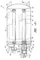
- FIG. 1 there is illustrated a jig dyeing machine 10 for use in rolling a fabric in and out of a dye bath 12 held within a containment trough 14.
- the jig dyeing machine 10 includes a first roller 16 supported along a first roller shaft 18 and a second roller 20 supported along a second roller shaft 22.
- the travel path includes an arrangement of guide rollers 26, 28, 30 mounted within the containment trough 14.
- the axes of the guide rollers extend in substantially in the same direction as the first roller 16 and the second roller 20.
- two of the guide rollers 26, 30 are located at a height below the intermediate guide roller 28 so as to increase the period of contact between the fabric 24 and the dye bath 12 within the containment trough 14.
- the intermediate guide roller 28 may be replaced with a vacuum box or the like if desired to further facilitate dye treatment.
- the fabric 24 is illustrated as having traveled through substantially one complete transfer between the first roller 16 and the second roller 20. That is, the fabric 24 has been substantially unwound from the first roller 16 and collected on the second roller 20.
- the fabric 24 thus defines a multi-layered fabric roll 32 which is collected around the second roller 20.
- the jig dyeing machine 10 may be operated at a substantially elevated temperature and pressure in a manner as will be well known to those of skill in the art. Such pressurized heated impregnation of the fabric 24 within the dye bath 12 may facilitate more rapid and uniform dye reaction.
- rollers 16, 20 rotate in the opposite direction.
- Motors 60, 60' (FIG. 2) power such rotation.
- the speed of the rollers 16, 20 is regulated so as to accommodate the relative changes in the diameter of the fabric rolls surrounding the rollers 16, 20 in order to ensure that the fabric 24 moves through the dye bath 12 at a substantially constant rate as the process continues.
- the first roller 16 is mounted such that the first roller shaft 18 is held in sliding axial relation to a pair of bearings 40 mounted at either end of the first roller shaft 18.
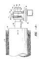
- the bearings 40 supporting the first roller shaft 18 are preferably mounted on a stationary platform 42 (FIG. 4) such that the bearings 40 remain in a substantially stationary position with relative movement taking place by axial oscillation of the first roller shaft 18. That is, the bearings 40 remain fixed while the roller shaft 18 carries the roller 16 axially relative to the bearings 40.
- the lateral axial movement of the first roller 16 during operation causes the edge of the fabric 24 to undergo a slight displacement during the winding and unwinding process thereby giving rise to a staggered edge configuration.
- a staggered edge configuration prevents the development of a substantially dog bone shaped fabric roll thereby promoting uniformity of treatment as the fabric 24 is passed through the dye bath 12.
- the oscillation of the first roller 16 is preferably carried out substantially without requiring the movement of any support or drive elements associated with the operation of the first roller 16.
- a power cylinder 44 is operatively connected to the first roller shaft 18 such that extension and retraction of a piston element 46 transfers axial movement to the first roller shaft 18.
- extension of the piston element 46 pushes the first roller shaft 18 away from the power cylinder 44 and retraction of the piston element 46 pulls the roller shaft towards the power cylinder 44.
- this arrangement may also be reversed if desired such as by mounting the power cylinder 44 at an appropriate location facing in the reverse direction.
- movement of the first roller shaft 18 corresponds to a like movement of the surrounding first roller 16 upon which the fabric 24 is carried.
- the movement of the first roller shaft 18 and surrounding first roller 16 may be carried out substantially without requiring movement of associated power structure or support elements.
- the piston element 46 is operatively connected to a rod assembly 48 including a pair of lateral rods 50, 52 extending in sliding relation through corresponding hollow guides 54, 56. As shown, the distal ends of the lateral rods 50, 52 are connected via a distal cross member 58 to one end of the first roller shaft 18.
- operative and structural members such as the drive motor 60 are disposed between the lateral rods 50, 52 so as to permit the rod assembly 48 to be shifted in the axial direction of the first roller shaft 18 without requiring movement of the drive motor 60 or the structural elements (including the bearings 40) supporting the first roller shaft 18.
- the lateral shifting movement of the first roller shaft 18 will preferably be in the order of several inches corresponding to the stroke of the piston element 46.
- a lateral shift in the range of about 1.5 to about 4 inches and more preferably about 2.5 inches may be desired.
- an adjustable length drive shaft assembly 62 is used to establish an operative driving connection between the drive motor 60 and the first roller shaft 18.
- the drive shaft assembly 62 incorporates a universal joint structure 64 such as a Curtis Universal Joint available from the Curtis Universal Joint Company located in Springfield, Massachusetts USA.
- such a universal joint structure permits the drive shaft assembly 62 to undergo a degree of variation by bending between the segments of the universal joint structure while nonetheless maintaining rotational movement through the drive shaft assembly 62. If desired, a degree of longitudinal extension and shortening of the drive shaft assembly 62 may also be permitted by such a structure. Accordingly, when the rod assembly 48 is shifted so as to place the drive shaft assembly 62 into compression, the drive shaft assembly 62 may undergo a degree of shortening and coordinated buckling out of the plane of the drawing such that the required operating length is achieved. The drive motor 60 can thus remain stationary while maintaining driving power to the first roller shaft 18.
- the use of the universal joint structure 64 provides the advantage of adapting to changes in the position of the attached roller shaft 18 during the life of the jig.
- the alignment height of the roller shaft 18 may change slightly.
- the flexibility of the universal joint structure 64 within the drive shaft assembly 62 readily accommodates such changes thereby avoiding undue stress on the system.
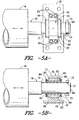
- the first roller shaft 18 is preferably mounted within the bearings 40 at reduced diameter hub portions 68 forming part of the first roller shaft 18.
- the reduced diameter hub portions 68 may be either integral with the first roller shaft 18 or may be separate attached elements. In either event, the diameter of the hub portion 68 is selected so as to ride within a bearing sleeve 70 of wear resistant material carried at the interior of the bearings 40.
- the bearing sleeve 70 may be bounded on the inboard side by a shoulder 71 at the position where the first roller shaft 18 necks down to the reduced diameter hub portion 68.
- the bearing sleeve 70 may be bounded on the outboard side by a collar 72 such as a split ring collar or the like held together by a pair of collar pins 73 carried within mating grooves at the end of the reduced diameter hub portion 68.
- a collar 72 such as a split ring collar or the like held together by a pair of collar pins 73 carried within mating grooves at the end of the reduced diameter hub portion 68.
- the second roller shaft 22 and associated surrounding roller 20 preferably remain substantially fixed in axial relation between a pair of opposing bearings 40' disposed at a fixed position at either end of the second roller shaft 22.
- the second roller shaft 22 is operatively connected to motor 60' by a drive shaft 62' incorporating a universal joint assembly as previously described but including a set pin 63' to substantially fix the operating longitudinal dimension of the drive shaft 62' while nonetheless maintaining a degree of flexibility to accommodate alignment changes within the second roller shaft over time.
- the relative movement between the first roller 16 and the second roller 20 is controlled by the axial movement of the first roller 16.
- the second roller shaft 22 could also be made to oscillate in an axial direction by use of an assembly similar to that illustrated and described in relation to the first roller shaft 18.
- a self lubricating and self aligning bearing assembly suitable for use with both the axially displaceable first roller shaft 18 as well as the fixed axial position second roller shaft 22 is illustrated in detail. Accordingly, while the bearing assembly is illustrated in relation to the axially displaceable first roller shaft 18 and the associated bearings 40, the illustrated assembly is likewise used in relation to the axially fixed second roller shaft 22 and its associated bearings 40'.
- the bearings 40, 40' are preferably held in a substantially fixed position which does not move.
- this fixed position is maintained by a pillow block 76 of split construction extending circumferentially around the bearings 40.
- the pillow block 76 includes an upper half ring segment 77 and a lower half ring segment 78.
- the upper and lower half ring segments 77, 78 are affixed to one another on either side by removable bolts 83 or the like to permit access to the bearing 40.
- the lower half ring segment 78 may include an outwardly projecting base 81 in the form of a plate structure for bolted attachment to a suitable support platform 42 (FIG. 4).
- the bearings 40 include a bushing 80 disposed in contacting surrounding relation to the bearing sleeve 70 which is disposed around the reduced diameter hub portion 68.
- the bushing 80 is formed from a self lubricating material such as a self lubricating polyimide graphite-fiber composite material.
- a self lubricating material such as a self lubricating polyimide graphite-fiber composite material.
- GRAPHALLOY Products having a place of business in Yonkers, NY, USA.
- the use of such materials in various bushing assemblies is illustrated and described in U.S. Patent 5,664,890 to Nowak et al. the teachings of which are incorporated by reference as if fully set forth herein.
- the bearing sleeve 70 is preferably formed of material having a highly wear resistant and smooth outer surface so as to minimize wear.
- One such material is a hardened chrome alloy material although other materials such as heat treated steel with a smooth surface or the like may also be used if desired.
- the bearings preferably also include a housing portion 82 which preferably has a substantially curved barrel shaped outer surface around a flat interior surface mated to and contacting the outer surface of the bushing 80. It is believe that the curved outer surface of the housing 82 provides a substantial benefit by promoting self alignment of the bearings 40 even if an irregularity develops in the hub portion 68 of the roller shaft 18 or in some other element within the overall structure. That is, pressure applied across the curved outer surface of the housing 82 causes that element to seek an equilibrium position relative to lower surface structures.
- annular bushing covering ring 84 is attached via bolts 86 or other attachment elements to either end of the assembly forming the bearings.
- the elements of the bearings 40 are contained at a substantially fixed position within the jig dyeing machine while nonetheless permitting the rotation of the hub portion 68 and attached sleeve element 70 relative to the bearings 40.
Landscapes
- Engineering & Computer Science (AREA)
- Textile Engineering (AREA)
- Treatment Of Fiber Materials (AREA)
Applications Claiming Priority (2)
| Application Number | Priority Date | Filing Date | Title |
|---|---|---|---|
| US286218 | 2002-11-01 | ||
| US10/286,218 US6685131B1 (en) | 2002-11-01 | 2002-11-01 | Jig for web treatment |
Publications (2)
| Publication Number | Publication Date |
|---|---|
| EP1416080A2 true EP1416080A2 (de) | 2004-05-06 |
| EP1416080A3 EP1416080A3 (de) | 2005-05-25 |
Family
ID=30443882
Family Applications (1)
| Application Number | Title | Priority Date | Filing Date |
|---|---|---|---|
| EP03090375A Withdrawn EP1416080A3 (de) | 2002-11-01 | 2003-11-01 | Jigger zur Behandlung von Geweben |
Country Status (2)
| Country | Link |
|---|---|
| US (1) | US6685131B1 (de) |
| EP (1) | EP1416080A3 (de) |
Cited By (2)
| Publication number | Priority date | Publication date | Assignee | Title |
|---|---|---|---|---|
| CN102454078A (zh) * | 2010-10-18 | 2012-05-16 | 吴江二练亚氏印染有限责任公司 | 自动卷染装置 |
| CN102454077A (zh) * | 2010-10-18 | 2012-05-16 | 吴江二练亚氏印染有限责任公司 | 捲染机装置 |
Families Citing this family (12)
| Publication number | Priority date | Publication date | Assignee | Title |
|---|---|---|---|---|
| DE102010029653B4 (de) * | 2010-02-02 | 2016-01-07 | Von Ardenne Gmbh | Substratbehandlungsanlage |
| KR101326332B1 (ko) * | 2012-05-04 | 2013-11-11 | (주)우양기계 | 지거 염색기의 권취롤러 왕복이송 권취장치 |
| CN106378339B (zh) * | 2016-11-28 | 2018-11-06 | 长沙理工大学 | 一种卷纸加工设备 |
| CN107067535B (zh) * | 2017-03-13 | 2023-03-24 | 深圳怡化电脑股份有限公司 | 纸币厚度检测基准轴安装结构及验钞装置 |
| CN107401014B (zh) * | 2017-08-02 | 2020-05-01 | 浙江深梦皮革科技有限公司 | 一种带抽真空装置的真空染色机 |
| CN107385740B (zh) * | 2017-08-02 | 2020-05-01 | 浙江深梦皮革科技有限公司 | 一种真空染色机 |
| CN107385738B (zh) * | 2017-08-02 | 2020-05-08 | 浙江深梦皮革科技有限公司 | 一种真空染色机上的截流装置 |
| US11945678B1 (en) * | 2021-11-22 | 2024-04-02 | Itool Equipment Holding Llc | Strut for a spool-holding rack and a spool-supporting axle assembly for use therewith |
| CN114261146B (zh) * | 2021-12-14 | 2024-03-22 | 龙游运城压纹制版有限公司 | 一种具有层次效果的高清压纹辊及其制备方法 |
| KR102644161B1 (ko) * | 2022-04-14 | 2024-03-07 | 주식회사 신양 | 원단 제조 장치 |
| KR102848388B1 (ko) * | 2022-12-09 | 2025-08-20 | 주식회사에이스기계 | 하이브리드형 콤비 지거염색기 |
| TWI822544B (zh) * | 2023-01-03 | 2023-11-11 | 福濃機械股份有限公司 | 軸桿調整裝置 |
Family Cites Families (9)
| Publication number | Priority date | Publication date | Assignee | Title |
|---|---|---|---|---|
| US2056071A (en) * | 1935-03-26 | 1936-09-29 | American Sheet & Tin Plate | Reel for metal strip |
| BE756850A (fr) * | 1969-10-03 | 1971-03-30 | Sulzer Ag | Dispositif d'enroulement du tissu sortant d'un metier ou d'une machine de traitement |
| DE2235839A1 (de) * | 1972-07-21 | 1974-01-31 | Erhardt & Leimer Kg | Faerbe-jigger |
| ES8608603A1 (es) * | 1985-08-07 | 1986-06-16 | Aplicaciones De Sistemas Ind S | Perfeccionamientos en maquinas jigger para el tratamiento continuo de materiales fibrosos en pieza |
| IT1230761B (it) * | 1989-02-20 | 1991-10-29 | Mezzera Spa | Macchina cosiddetta jigger, per la tintura di un tessuto in largo, con passaggio del tessuto a va e vieni attraverso ad un bagno di tintura |
| FR2725219B1 (fr) | 1994-09-29 | 1996-12-20 | Inst Textile De France | Procede et appareil d'ennoblissement textile, du type jigger, mettant en oeuvre des ondes electromagnetiques |
| US5549394A (en) | 1994-11-10 | 1996-08-27 | Hycomp, Inc. | Bearing arrangement having a polyimide graphite-fiber reinforced composite embedded therein |
| FI107908B (fi) * | 1998-11-04 | 2001-10-31 | Metso Paper Inc | Menetelmä ja laitteisto rullan rakenteen hallitsemiseksi |
| US6145783A (en) * | 1999-04-02 | 2000-11-14 | Gmp Co., Ltd. | Device for adjusting the position of film rolls in laminators |
-
2002
- 2002-11-01 US US10/286,218 patent/US6685131B1/en not_active Expired - Fee Related
-
2003
- 2003-11-01 EP EP03090375A patent/EP1416080A3/de not_active Withdrawn
Cited By (2)
| Publication number | Priority date | Publication date | Assignee | Title |
|---|---|---|---|---|
| CN102454078A (zh) * | 2010-10-18 | 2012-05-16 | 吴江二练亚氏印染有限责任公司 | 自动卷染装置 |
| CN102454077A (zh) * | 2010-10-18 | 2012-05-16 | 吴江二练亚氏印染有限责任公司 | 捲染机装置 |
Also Published As
| Publication number | Publication date |
|---|---|
| US6685131B1 (en) | 2004-02-03 |
| EP1416080A3 (de) | 2005-05-25 |
Similar Documents
| Publication | Publication Date | Title |
|---|---|---|
| US6685131B1 (en) | Jig for web treatment | |
| FI71607B (fi) | Vals av manteltyp | |
| FI86095B (fi) | Pressanordning foer torkning av en pappersbana. | |
| US4299017A (en) | Apparatus for smooth rolling the bearing seats of crankshafts | |
| US4389932A (en) | Calender with composite outermost rolls | |
| RU1838490C (ru) | Нажимной валок с регулируемым прогибом | |
| FI69150B (fi) | Foerfarande foer drivande av ett valsaggregat foer banor och valsaggregat foer tillaempande av foerfarandet | |
| JPH0780603B2 (ja) | 巻取装置のためのローラー | |
| US4194275A (en) | Spreader roll | |
| US4069569A (en) | Deflection-controlled roll for the pressure treatment of materials in web form | |
| US6261369B1 (en) | Sink roll for galvanizing bath | |
| EP0534999B1 (de) | Durchbiegungssteuerbare walze mit hitzeschwelle | |
| EP0501327B1 (de) | Galette | |
| US5813960A (en) | Press roll and machine with press roll | |
| US4856155A (en) | Method and device in an adjustable-crown roll | |
| US5193258A (en) | Self-loading controlled deflection roll | |
| EP3913134B1 (de) | Bandwalze | |
| US6796929B2 (en) | Self-adjusting deflection controlled roll | |
| US7162953B2 (en) | Roll arrangement | |
| JP2003213590A (ja) | 紙シートのカレンダ装置 | |
| US4324122A (en) | Metal strip cold-reduction mill | |
| US4504359A (en) | Assembly for treatment of an endless wire or felt | |
| FI109372B (fi) | Telan käyttöjärjestely | |
| US3418703A (en) | Antideflection roll with non-rotating beam and lever supports | |
| US5183620A (en) | Process of drawing yarn using an oscillating draw assist element |
Legal Events
| Date | Code | Title | Description |
|---|---|---|---|
| PUAI | Public reference made under article 153(3) epc to a published international application that has entered the european phase |
Free format text: ORIGINAL CODE: 0009012 |
|
| AK | Designated contracting states |
Kind code of ref document: A2 Designated state(s): AT BE BG CH CY CZ DE DK EE ES FI FR GB GR HU IE IT LI LU MC NL PT RO SE SI SK TR |
|
| AX | Request for extension of the european patent |
Extension state: AL LT LV MK |
|
| PUAL | Search report despatched |
Free format text: ORIGINAL CODE: 0009013 |
|
| AK | Designated contracting states |
Kind code of ref document: A3 Designated state(s): AT BE BG CH CY CZ DE DK EE ES FI FR GB GR HU IE IT LI LU MC NL PT RO SE SI SK TR |
|
| AX | Request for extension of the european patent |
Extension state: AL LT LV MK |
|
| 17P | Request for examination filed |
Effective date: 20051111 |
|
| AKX | Designation fees paid |
Designated state(s): AT BE BG CH CY CZ DE DK EE ES FI FR GB GR HU IE IT LI LU MC NL PT RO SE SI SK TR |
|
| GRAP | Despatch of communication of intention to grant a patent |
Free format text: ORIGINAL CODE: EPIDOSNIGR1 |
|
| STAA | Information on the status of an ep patent application or granted ep patent |
Free format text: STATUS: THE APPLICATION IS DEEMED TO BE WITHDRAWN |
|
| 18D | Application deemed to be withdrawn |
Effective date: 20070503 |