EP1416155A1 - Steuerungssystem und Verfahren für eine Brennkraftmaschine - Google Patents
Steuerungssystem und Verfahren für eine Brennkraftmaschine Download PDFInfo
- Publication number
- EP1416155A1 EP1416155A1 EP20030103764 EP03103764A EP1416155A1 EP 1416155 A1 EP1416155 A1 EP 1416155A1 EP 20030103764 EP20030103764 EP 20030103764 EP 03103764 A EP03103764 A EP 03103764A EP 1416155 A1 EP1416155 A1 EP 1416155A1
- Authority
- EP
- European Patent Office
- Prior art keywords
- engine
- change
- ignition timing
- egr
- sensor
- Prior art date
- Legal status (The legal status is an assumption and is not a legal conclusion. Google has not performed a legal analysis and makes no representation as to the accuracy of the status listed.)
- Withdrawn
Links
- 238000002485 combustion reaction Methods 0.000 title claims abstract description 67
- 238000000034 method Methods 0.000 title claims abstract description 30
- 239000000446 fuel Substances 0.000 claims abstract description 43
- 239000007789 gas Substances 0.000 claims description 77
- 238000011144 upstream manufacturing Methods 0.000 claims description 7
- 238000004590 computer program Methods 0.000 abstract description 2
- 230000001276 controlling effect Effects 0.000 description 12
- 230000000694 effects Effects 0.000 description 9
- 230000007423 decrease Effects 0.000 description 8
- 239000003054 catalyst Substances 0.000 description 6
- 239000000203 mixture Substances 0.000 description 5
- 230000000875 corresponding effect Effects 0.000 description 4
- 230000003247 decreasing effect Effects 0.000 description 4
- 238000010586 diagram Methods 0.000 description 4
- UGFAIRIUMAVXCW-UHFFFAOYSA-N Carbon monoxide Chemical compound [O+]#[C-] UGFAIRIUMAVXCW-UHFFFAOYSA-N 0.000 description 2
- 238000013459 approach Methods 0.000 description 2
- 230000005540 biological transmission Effects 0.000 description 2
- 229910002091 carbon monoxide Inorganic materials 0.000 description 2
- 230000003197 catalytic effect Effects 0.000 description 2
- 229930195733 hydrocarbon Natural products 0.000 description 2
- 150000002430 hydrocarbons Chemical class 0.000 description 2
- 238000002347 injection Methods 0.000 description 2
- 239000007924 injection Substances 0.000 description 2
- 230000000717 retained effect Effects 0.000 description 2
- 230000005355 Hall effect Effects 0.000 description 1
- GQPLMRYTRLFLPF-UHFFFAOYSA-N Nitrous Oxide Chemical class [O-][N+]#N GQPLMRYTRLFLPF-UHFFFAOYSA-N 0.000 description 1
- 101100512783 Saccharomyces cerevisiae (strain ATCC 204508 / S288c) MEH1 gene Proteins 0.000 description 1
- 230000001133 acceleration Effects 0.000 description 1
- 230000006399 behavior Effects 0.000 description 1
- 230000015572 biosynthetic process Effects 0.000 description 1
- 238000004891 communication Methods 0.000 description 1
- 230000006835 compression Effects 0.000 description 1
- 238000007906 compression Methods 0.000 description 1
- 239000000470 constituent Substances 0.000 description 1
- 239000002826 coolant Substances 0.000 description 1
- 238000001816 cooling Methods 0.000 description 1
- 230000002596 correlated effect Effects 0.000 description 1
- 238000006073 displacement reaction Methods 0.000 description 1
- 238000010304 firing Methods 0.000 description 1
- 239000012530 fluid Substances 0.000 description 1
- 239000002828 fuel tank Substances 0.000 description 1
- 238000004519 manufacturing process Methods 0.000 description 1
- 238000012986 modification Methods 0.000 description 1
- 230000004048 modification Effects 0.000 description 1
- 230000003287 optical effect Effects 0.000 description 1
Images


Classifications
-
- F—MECHANICAL ENGINEERING; LIGHTING; HEATING; WEAPONS; BLASTING
- F02—COMBUSTION ENGINES; HOT-GAS OR COMBUSTION-PRODUCT ENGINE PLANTS
- F02D—CONTROLLING COMBUSTION ENGINES
- F02D41/00—Electrical control of supply of combustible mixture or its constituents
- F02D41/0025—Controlling engines characterised by use of non-liquid fuels, pluralities of fuels, or non-fuel substances added to the combustible mixtures
- F02D41/0047—Controlling exhaust gas recirculation [EGR]
- F02D41/006—Controlling exhaust gas recirculation [EGR] using internal EGR
- F02D41/0062—Estimating, calculating or determining the internal EGR rate, amount or flow
-
- F—MECHANICAL ENGINEERING; LIGHTING; HEATING; WEAPONS; BLASTING
- F02—COMBUSTION ENGINES; HOT-GAS OR COMBUSTION-PRODUCT ENGINE PLANTS
- F02D—CONTROLLING COMBUSTION ENGINES
- F02D41/00—Electrical control of supply of combustible mixture or its constituents
- F02D41/0025—Controlling engines characterised by use of non-liquid fuels, pluralities of fuels, or non-fuel substances added to the combustible mixtures
- F02D41/0047—Controlling exhaust gas recirculation [EGR]
- F02D41/0065—Specific aspects of external EGR control
- F02D41/0072—Estimating, calculating or determining the EGR rate, amount or flow
-
- F—MECHANICAL ENGINEERING; LIGHTING; HEATING; WEAPONS; BLASTING
- F02—COMBUSTION ENGINES; HOT-GAS OR COMBUSTION-PRODUCT ENGINE PLANTS
- F02D—CONTROLLING COMBUSTION ENGINES
- F02D41/00—Electrical control of supply of combustible mixture or its constituents
- F02D41/02—Circuit arrangements for generating control signals
- F02D41/14—Introducing closed-loop corrections
- F02D41/1438—Introducing closed-loop corrections using means for determining characteristics of the combustion gases; Sensors therefor
- F02D41/1444—Introducing closed-loop corrections using means for determining characteristics of the combustion gases; Sensors therefor characterised by the characteristics of the combustion gases
- F02D41/1448—Introducing closed-loop corrections using means for determining characteristics of the combustion gases; Sensors therefor characterised by the characteristics of the combustion gases the characteristics being an exhaust gas pressure
-
- F—MECHANICAL ENGINEERING; LIGHTING; HEATING; WEAPONS; BLASTING
- F02—COMBUSTION ENGINES; HOT-GAS OR COMBUSTION-PRODUCT ENGINE PLANTS
- F02P—IGNITION, OTHER THAN COMPRESSION IGNITION, FOR INTERNAL-COMBUSTION ENGINES; TESTING OF IGNITION TIMING IN COMPRESSION-IGNITION ENGINES
- F02P5/00—Advancing or retarding ignition; Control therefor
- F02P5/04—Advancing or retarding ignition; Control therefor automatically, as a function of the working conditions of the engine or vehicle or of the atmospheric conditions
- F02P5/045—Advancing or retarding ignition; Control therefor automatically, as a function of the working conditions of the engine or vehicle or of the atmospheric conditions combined with electronic control of other engine functions, e.g. fuel injection
-
- F—MECHANICAL ENGINEERING; LIGHTING; HEATING; WEAPONS; BLASTING
- F02—COMBUSTION ENGINES; HOT-GAS OR COMBUSTION-PRODUCT ENGINE PLANTS
- F02P—IGNITION, OTHER THAN COMPRESSION IGNITION, FOR INTERNAL-COMBUSTION ENGINES; TESTING OF IGNITION TIMING IN COMPRESSION-IGNITION ENGINES
- F02P5/00—Advancing or retarding ignition; Control therefor
- F02P5/04—Advancing or retarding ignition; Control therefor automatically, as a function of the working conditions of the engine or vehicle or of the atmospheric conditions
- F02P5/145—Advancing or retarding ignition; Control therefor automatically, as a function of the working conditions of the engine or vehicle or of the atmospheric conditions using electrical means
- F02P5/15—Digital data processing
- F02P5/1502—Digital data processing using one central computing unit
- F02P5/1512—Digital data processing using one central computing unit with particular means concerning an individual cylinder
-
- F—MECHANICAL ENGINEERING; LIGHTING; HEATING; WEAPONS; BLASTING
- F02—COMBUSTION ENGINES; HOT-GAS OR COMBUSTION-PRODUCT ENGINE PLANTS
- F02P—IGNITION, OTHER THAN COMPRESSION IGNITION, FOR INTERNAL-COMBUSTION ENGINES; TESTING OF IGNITION TIMING IN COMPRESSION-IGNITION ENGINES
- F02P5/00—Advancing or retarding ignition; Control therefor
- F02P5/04—Advancing or retarding ignition; Control therefor automatically, as a function of the working conditions of the engine or vehicle or of the atmospheric conditions
- F02P5/145—Advancing or retarding ignition; Control therefor automatically, as a function of the working conditions of the engine or vehicle or of the atmospheric conditions using electrical means
- F02P5/15—Digital data processing
- F02P5/1502—Digital data processing using one central computing unit
- F02P5/1516—Digital data processing using one central computing unit with means relating to exhaust gas recirculation, e.g. turbo
-
- F—MECHANICAL ENGINEERING; LIGHTING; HEATING; WEAPONS; BLASTING
- F02—COMBUSTION ENGINES; HOT-GAS OR COMBUSTION-PRODUCT ENGINE PLANTS
- F02D—CONTROLLING COMBUSTION ENGINES
- F02D35/00—Controlling engines, dependent on conditions exterior or interior to engines, not otherwise provided for
- F02D35/02—Controlling engines, dependent on conditions exterior or interior to engines, not otherwise provided for on interior conditions
- F02D35/025—Controlling engines, dependent on conditions exterior or interior to engines, not otherwise provided for on interior conditions by determining temperatures inside the cylinder, e.g. combustion temperatures
- F02D35/026—Controlling engines, dependent on conditions exterior or interior to engines, not otherwise provided for on interior conditions by determining temperatures inside the cylinder, e.g. combustion temperatures using an estimation
-
- F—MECHANICAL ENGINEERING; LIGHTING; HEATING; WEAPONS; BLASTING
- F02—COMBUSTION ENGINES; HOT-GAS OR COMBUSTION-PRODUCT ENGINE PLANTS
- F02D—CONTROLLING COMBUSTION ENGINES
- F02D41/00—Electrical control of supply of combustible mixture or its constituents
- F02D41/02—Circuit arrangements for generating control signals
- F02D41/14—Introducing closed-loop corrections
- F02D41/1438—Introducing closed-loop corrections using means for determining characteristics of the combustion gases; Sensors therefor
- F02D41/1439—Introducing closed-loop corrections using means for determining characteristics of the combustion gases; Sensors therefor characterised by the position of the sensor
- F02D41/1441—Plural sensors
-
- F—MECHANICAL ENGINEERING; LIGHTING; HEATING; WEAPONS; BLASTING
- F02—COMBUSTION ENGINES; HOT-GAS OR COMBUSTION-PRODUCT ENGINE PLANTS
- F02D—CONTROLLING COMBUSTION ENGINES
- F02D41/00—Electrical control of supply of combustible mixture or its constituents
- F02D41/02—Circuit arrangements for generating control signals
- F02D41/14—Introducing closed-loop corrections
- F02D41/1438—Introducing closed-loop corrections using means for determining characteristics of the combustion gases; Sensors therefor
- F02D41/1444—Introducing closed-loop corrections using means for determining characteristics of the combustion gases; Sensors therefor characterised by the characteristics of the combustion gases
- F02D41/1446—Introducing closed-loop corrections using means for determining characteristics of the combustion gases; Sensors therefor characterised by the characteristics of the combustion gases the characteristics being exhaust temperatures
-
- Y—GENERAL TAGGING OF NEW TECHNOLOGICAL DEVELOPMENTS; GENERAL TAGGING OF CROSS-SECTIONAL TECHNOLOGIES SPANNING OVER SEVERAL SECTIONS OF THE IPC; TECHNICAL SUBJECTS COVERED BY FORMER USPC CROSS-REFERENCE ART COLLECTIONS [XRACs] AND DIGESTS
- Y02—TECHNOLOGIES OR APPLICATIONS FOR MITIGATION OR ADAPTATION AGAINST CLIMATE CHANGE
- Y02T—CLIMATE CHANGE MITIGATION TECHNOLOGIES RELATED TO TRANSPORTATION
- Y02T10/00—Road transport of goods or passengers
- Y02T10/10—Internal combustion engine [ICE] based vehicles
- Y02T10/40—Engine management systems
Definitions
- This invention relates to a method and system for controlling an engine and in particular to a method and system for controlling the ignition timing of a spark ignited engine.
- EGR exhaust gas recirculation
- barometric pressure tables barometric pressure tables
- air-fuel tables air-fuel tables
- each of these engine parameters has been treated independently when controlling ignition timing leading to complex control methods.
- an engine parameter such as an EGR rate
- an EGR based adjustment to ignition timing that was not calibrated for varying barometric pressure might result in non-optimal ignition timing.
- a barometric pressure based adjustment to ignition timing would not-include the effect of EGR changes.
- all these tables might not provide optimal adjustment of ignition timing for varying barometer and EGR conditions.
- a high altitude vehicle may utilize a barometric pressure table to control ignition timing while shutting off EGR, or not use an EGR table for ignition timing adjustment.
- a high altitude vehicle may not perform optimally at sea-level when EGR may be desirable.
- a low altitude vehicle utilizing an EGR table may not perform optimally at relatively high altitudes because the affect of barometric pressure on the EGR table may be unknown.
- a method for controlling ignition timing of an engine having at least one engine cylinder characterised in that the method comprises determining a change in a combustion temperature within the engine based on a change in at least one engine operating parameter and adjusting the ignition timing of the engine based on the change of combustion temperature.
- the change in combustion temperature may be a change in combustion temperature rise.
- the engine operating parameter may be an exhaust gas recirculation rate of exhaust gases into an intake manifold of the engine.
- the engine operating parameter may be an exhaust gas pressure downstream of at least one cylinder of the engine and upstream of an emission control device.
- the engine operating parameter may be an air-fuel ratio of the engine.
- the or each cylinder of the engine may communicate with an emission control device and the method may further comprise determining the change in combustion temperature within the engine based on a change in exhaust gas pressure upstream of the emission control device and the change in air-fuel ratio in at least one cylinder of the engine and the ignition timing of the engine is adjusted based on the change of combustion temperature.
- the change in combustion temperature rise in the engine may be further determined from a change in an amount of exhaust gas recirculation into an intake manifold of the engine.
- the step of adjusting the ignition timing may include determining a base ignition value based on an engine operating condition, determining an adjustment ignition value from the change of combustion temperature in the engine and determining a commanded ignition timing value based on the base ignition value and the adjustment ignition value.
- a system for controlling ignition timing of an engine having an intake manifold communicating with one or more engine cylinders characterised in that the system comprises a first sensor generating a first signal indicative of an engine operating parameter and a controller operably coupled to the first sensor, wherein the controller is configured to determine a change in combustion temperature within the engine based on a change in the engine operating parameter and to adjust the ignition timing of the engine based on the change of combustion temperature.
- the change in combustion temperature may be a change in combustion temperature rise.
- the first sensor may be an air flow sensor disposed in the intake manifold and the engine operating parameter is an air flow rate.
- the first sensor may be an exhaust gas sensor disposed downstream of at least one cylinder of the engine and the engine operating parameter is an air-fuel ratio.
- the first sensor may be a pressure sensor and the engine operating parameter is an exhaust gas pressure.
- an article of manufacture comprising a computer storage medium having a computer program encoded therein for controlling ignition timing of an engine, the engine having an engine cylinder, the computer storage medium comprising code for determining a change in a combustion temperature rise within the engine based on a change in at least one engine operating parameter and code for adjusting the ignition timing of the engine based on the change of combustion temperature rise.
- the engine operating parameter may comprise of one of an exhaust gas recirculation rate of exhaust gases into an intake manifold communicating with the engine cylinder, an exhaust gas pressure downstream of the cylinder and upstream of an emission control device and an air-fuel ratio of the engine.
- the code for adjusting the ignition timing may include code for determining a base ignition value based on an engine operating condition, code for determining an adjustment ignition value from the change of combustion temperature in the engine and code for determining a commanded ignition timing value based on the base ignition value and the adjustment ignition value.
- An advantage of the present invention is that the proposed new ignition control methodology allows vehicles to have optimal ignition timing at either relatively high altitudes or sea-level altitudes. This advantage is obtained because the contribution of changes in an air-fuel ratio, an EGR rate, and an exhaust pressure can simultaneously be directly related to a temperature rise, which is thereafter directly related to an ignition timing value.
- a further advantage of the present invention is that improved vehicle fuel economy is obtained due to an optimal work torque being produced by the optimal ignition timing.
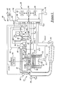
- an automotive vehicle 10 includes an internal combustion engine 12 and an engine control system 14.
- Engine 12 may include a plurality of cylinders; however only one cylinder is shown for clarity of illustration.
- Engine 12 may further include a combustion chamber 30, cylinder walls 32, a piston 34, a crankshaft 35, a spark plug 36, an intake manifold 38, an exhaust manifold 40, an EGR conduit 41, an intake valve 42, an exhaust valve 44, a throttle body 46, a throttle plate 48, an EGR valve 49, a fuel injector 50, and a catalytic converter 52.
- Combustion chamber 30 communicates with intake manifold 38 and exhaust manifold 40 via respective intake and exhaust valves 42, 44.
- Piston 34 is positioned within combustion chamber 30 between cylinder walls 32 and is connected to crankshaft 35. Ignition of an air-fuel mixture within combustion chamber 30 is controlled via spark plug 36 which delivers ignition spark responsive to a signal from an ignition system 54. The control of ignition timing in combustion chamber 30 will be described in greater detail below.
- Intake manifold 38 communicates with throttle body 46 via throttle plate 48. Throttle plate 48 is controlled by electric motor 55 which receives a signal from ETC driver 56. ETC driver 56 receives a control signal (DC) from a controller 58. Intake manifold 38 is also shown having fuel injector 50 coupled thereto for delivering fuel in proportion to the pulse width of signals (FPW) from controller 58. Fuel is delivered to fuel injector 50 by a fuel system (not shown) including a fuel tank, fuel pump, and fuel rail (not shown). Although port fuel injection is shown, other methods such as direction fuel injection could be utilized to control fueling.
- Exhaust manifold 40 communicates with catalyst 52, respectively, which may comprise a three-way catalytic converter for example.
- Catalyst 52 reduces exhaust gas constituents such as nitrous oxides (NOx) and oxidizes carbon monoxide (CO) and hydrocarbons (HC).
- NOx nitrous oxides
- CO carbon monoxide
- HC hydrocarbons
- EGR conduit 41 is provided to recirculate exhaust gases from exhaust manifold 40 to intake manifold 38. The recirculation of exhaust gases into the intake air reduces the temperatures reached during combustion which reduces the formation of NOx. Flow of exhaust gases through EGR conduit 41 is controlled by valve 49 disposed within conduit 41. Valve 49 is controlled via signal (EG) generated by controller 58.
- EG signal
- Control system 14 is provided to control the operation of engine 12 and to implement a method for controlling ignition timing within cylinders of engine 12.
- Control system 14 includes an ignition system 54, an electric motor 55 for controlling throttle plate 48, an ETC driver 56, EGR flow sensor 57, exhaust pressure sensor 59, exhaust gas sensors 60, 64, a mass air flow sensor 68, a intake pressure sensor 69, a temperature sensor 70, a throttle position sensor 72, a torque sensor 74, an engine speed sensor 76, a pedal position sensor 78, an accelerator pedal 80, and controller 58.
- EGR flow sensor 57 is provided to measure the EGR flow through conduit 41. Sensor 57 is in fluid communication with conduit 41 and generates signal (EG) indicative of an EGR flow rate within conduit 41. Signal (EG) is received by controller 58.
- Exhaust pressure sensor 59 is provided to measure the exhaust pressure in manifold 40 due to exhaust gases.
- sensor 59 may generate a signal (P exh ) indicative of the exhaust pressure in manifold 40 that is received by controller 58.
- the exhaust pressure may be inferred from engine operating parameters in lieu of using sensor 59.
- Exhaust gas sensor 60 is disposed upstream of catalyst 52 and exhaust gas sensor 64 is disposed downstream of catalyst 52.
- Exhaust gas sensors 60, 64 may comprise one of an EGO sensor, an HEGO sensor, or a UEGO sensor.
- Sensor 60 may generate signal EGO1 indicative of an air/fuel ratio in exhaust gases upstream of catalyst 52.
- Sensor 64 may generate signal EGO2 indicative of an air/fuel ratio in exhaust gases downstream of catalyst 52.
- Mass air flow rate sensor 68 generates a signal transmitted to controller 58 indicating the inducted air flow ( m ⁇ air ) rate. Controller 58 can utilize value ( m ⁇ air ) to determine the mass of air (m ⁇ air ) inducted per cylinder firing event. Sensor 68 may be coupled to the throttle body 46 or intake manifold 38.
- Intake pressure sensor 69 is provided to measure a pressure in intake manifold 38.
- sensor 69 may generate a signal (P int ) indicative of the pressure in manifold 38 that is received by controller 58.
- the intake pressure (P int ) may be inferred from the air flow rate sensor 68 signal.
- Temperature sensor 70 generates a signal (T int ) that is received by controller 58 indicative of a temperature of intake gases in intake manifold 38.
- Temperature sensor 71 generates a signal (ECT) that is received by controller 58 indicative of an engine coolant temperature.
- Sensor 71 may be coupled to cooling jacket 73 in cylinder wall 32.
- Throttle position sensor 72 generates a signal indicating a throttle position (TP) of throttle plate 48 received by controller 58 for closed-loop control of plate 48.
- Torque sensor 74 generates a signal (TQ) that may indicate one of following torque values:-
- Engine speed sensor 76 may comprise a Hall effect sensor that generates a signal (N) used to indicate an engine speed. Sensor 76 may be coupled to crankshaft 35 and transmits signal (N) to controller 58.
- Accelerator pedal 80 is shown communicating with a driver's foot 82.
- Pedal position sensor 78 generates a signal indicating acceleration pedal position (PP) that is transmitted to controller 58.
- PP acceleration pedal position
- the controller 58 is used to implement the method for controlling ignition timing of engine 12 in accordance with the present invention.
- the controller 58 includes a microprocessor 84 communicating with various computer-readable storage media.
- the computer readable storage media preferably include nonvolatile and volatile storage in a read-only memory (ROM) 86 and a random-access memory (RAM) 88.
- the computer readable media may be implemented using any of a number of known memory devices such as PROMS, EPROMs, EEPROMs, flash memory or any other electric, magnetic, optical or combination memory device capable of storing data, some of which represent executable instructions used by microprocessor 84 in controlling engine 12.
- Microprocessor 84 communicates with various sensors and actuators (discussed above) via an input/output (I/O) interface 90.
- I/O input/output
- the present invention could utilize more than one physical controller to provide engine/vehicle control depending upon the particular application.
- the inventor herein has recognized that changing one or more of the EGR rate, the exhaust pressure (P exh ), and the air-fuel ratio (AF) will affect the magnitude of a combustion temperature rise in a cylinder. Further, the inventor herein has also recognized that when the change in combustion temperature rise is known, the ignition timing can be adjusted based on the change in combustion temperature rise. Before proceeding with a detailed explanation of the inventive method for adjusting ignition timing, the effect on the combustion temperature rise due to changes to the EGR rate, the exhaust pressure (P exh ), and the air-fuel ratio will be described.
- Residual gases in a cylinder during a combustion event are those gases that resulted from a prior combustion event.
- residual gases include both (i) the combusted gases that remain in a cylinder above the TDC piston position (i.e., in a clearance volume of the cylinder) after an exhaust stroke, and (ii) the combusted gases that are expelled into an intake manifold during an intake stroke and subsequently re-inducted into the cylinder during the intake stroke.
- Figure 3 illustrates a diagram of volumetric efficiency (e vi ) versus the ratio of intake pressure and exhaust pressure (P int /P exh ).
- Volumetric efficiency is a ratio of an actual amount of air inducted into a cylinder and a maximum possible amount of air that can be inducted into the cylinder at the same temperature and pressure.
- the curve 92 corresponds to the mass of air (m air ) inducted into a cylinder.
- the curve 92 approaches the value 1.0 as the intake manifold to exhaust pressure ratio approaches 1.0.
- the area below the line 1.0 and above curve 92 corresponds to residual gases that expand back into the intake manifold and are drawn back in during the intake stroke.
- the area above the line 1.0 and below dashed line 93 corresponds to residual gas left in the cylinder clearance volume.
- the area above curve 92 and below dashed line 93 thus corresponds to the amount of residual gases in the cylinder.
- the residual gas amounts include:
- the amount of residual gases increases.
- the residual gases include the sum of residual gases retained in the clearance volume (m cv ) and residual gases drawn back into the cylinder (m dbi ).
- the residual gases include the sum of residual gases in the clearance volume (m cv ), the residual gases drawn back into the cylinder (m dbi ) , and the EGR mass (m egr ) .
- the volumetric efficiency and air mass (m air )) decreases when EGR is utilized.
- the amount of residual gases delivered into the cylinder decreases.
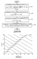
- FIG 7 is a plot of lines of constant temperature rise as EGR percentage value (%EGR) and air-fuel ratio (AF) are changed. Further, Figure 7 illustrates how changing the values (%EGR) or (AF) both affect the combustion temperature rise.
- the diagram further illustrates the effect of changing an air-fuel ratio on the combustion temperature rise in a cylinder.
- air-fuel ratio in a cylinder is adjusted leaner the combustion temperature rise is decreased.
- (%EGR) is 1% as air-fuel ratio (AF) is increased from 16.5 to 18, the combustion temperature rise decreases from 2400° F to 2000° F.
- the air-fuel ratio in the cylinder is adjusted richer the combustion temperature rise is increased.
- air-fuel ratio (AF) is decreased from 18 to 16.5 at (%EGR) equal to 1%
- the combustion temperature rise increases from 2000° F to 2400° F.
- the current value of exhaust pressure (P exh ) can be determined using pressure sensor 59 disposed in exhaust manifold 59. Alternately, the exhaust pressure (P exh ) can be inferred by using steps 114-120 of Figure 6B.
- a total cylinder charge (m cyl ) is determined using the following equation:
- the total cylinder mass flow rate ( m ⁇ cyl ) flowing through the engine over a standard time interval is determined from the total charge per cylinder ( m cyl )and engine speed N.
- FIG. 2 a schematic of an engine is provided showing the various flow rates therethrough.
- the cylinder gas flow rate through the engine m ⁇ cyl is equal to the sum of exhaust gas flow rate m ⁇ exh and the EGR flow rate m ⁇ egr . Accordingly, the earlier equation can be derived from this relationship.
- the current exhaust gas pressure (P exh ) is determined from the exhaust gas flow rate ( m ⁇ exh ) and an atmospheric pressure (P atmos ).
- the pressure (P atmos ) can be determined from a pressure sensor (not shown) communicating with atmospheric pressure and transmitting a signal to controller 58.
- the pressure (P atmos ) could be inferred from a vehicle altitude determined from GPS positional signals.
- the GPS positional signals could be received by a GPS receiver (not shown) operably communicating with controller 58.
- step 100 a change in exhaust gas recirculation percentage ( ⁇ %EGR) from a nominal base value corresponding to the base spark advance setting is determined.
- %EGR 100 ⁇ m egr m egr + m air
- ⁇ %EGR 100 ⁇ m egr m egr + m air
- ⁇ %EGR %EGR actual - %EGR no min al
- %EGR no min al the nominal or base %EGR value corresponding to base spark timing
- %EGR actual the actual %EGR value based on measured or inferred EGR mass flow rate.
- a change in a combustion temperature rise is determined based on the change in the exhaust pressure ( ⁇ P exh ). the change in the EGR percentage ( ⁇ %EGR), and the change in the air-fuel ratio ( ⁇ AF).
- step 104 the mathematical equations used to determine the change in the temperature rise will now be explained.
- a gradient ( ⁇ ( ⁇ T) of the temperature rise is a vector that defines the direction of maximum possible variation of the temperature rise (AT) due to changes in EGR, the exhaust pressure (P exh ), and the air-fuel ratio (AF).
- ⁇ T / ⁇ % EGR is a partial derivative defining the change in temperature rise ( ⁇ T) due to a change in %EGR
- ⁇ T / ⁇ % EGR is a partial derivative defining the change in temperature rise ( ⁇ T) due to a change in %EGR
- ⁇ ⁇ T / ⁇ P exh is a partial derivative defining the change in temperature rise ( ⁇ T) due to a change in P exh
- ⁇ T / ⁇ AF is a partial derivative defining the change in temperature rise ( ⁇ T) due to a change in
- step 106 determines a base ignition timing value (IT 0 ) from engine operating conditions.
- controller 58 can determine ignition timing value (IT 0 ) by accessing a lookup table of ignition timing values indexed by engine speed and air mass (AM), with the nominal value %EGR nominal assumed.
- step 112 the ignition timing in an engine cylinder is controlled based on the desired ignition timing value (IT).
- a system and method for controlling ignition timing provides a substantial advantage over conventional systems and methods.
- the system and method allows vehicles to have optimal ignition timing at either relatively high altitudes or sea-level altitudes.
- This advantage is obtained because the contribution of a change in EGR, a change in exhaust pressure (P exh ), and a change in air-fuel ratio (AF) are each directly related to change in temperature rise in an engine cylinder.
- P exh exhaust pressure
- AF air-fuel ratio
- the inventor herein has recognized that there is a common property of combustion (i.e., a temperature rise during combustion) that is directly related to a combustion rate in an engine cylinder and an optimal ignition timing.
- the temperature rise during combustion is directly affected by engine operating parameters such as an air-fuel ratio, an exhaust gas recirculation (EGR) rate, and an exhaust gas pressure downstream of an engine cylinder.
- EGR exhaust gas recirculation
- the inventor herein has recognized that changes in each of the engine operating parameters can be directly related to changes in the temperature rise during combustion. Thereafter, the ignition timing can be controlled based on that same change in temperature rise which greatly simplifies the vehicle calibration and ignition control implementation.
Landscapes
- Engineering & Computer Science (AREA)
- Chemical & Material Sciences (AREA)
- Combustion & Propulsion (AREA)
- Mechanical Engineering (AREA)
- General Engineering & Computer Science (AREA)
- Theoretical Computer Science (AREA)
- Signal Processing (AREA)
- Combined Controls Of Internal Combustion Engines (AREA)
- Output Control And Ontrol Of Special Type Engine (AREA)
- Electrical Control Of Air Or Fuel Supplied To Internal-Combustion Engine (AREA)
- Electrical Control Of Ignition Timing (AREA)
Applications Claiming Priority (2)
| Application Number | Priority Date | Filing Date | Title |
|---|---|---|---|
| US281937 | 1981-07-10 | ||
| US10/281,937 US6845753B2 (en) | 2002-10-29 | 2002-10-29 | System and method for controlling ignition timing in an engine |
Publications (1)
| Publication Number | Publication Date |
|---|---|
| EP1416155A1 true EP1416155A1 (de) | 2004-05-06 |
Family
ID=32093463
Family Applications (1)
| Application Number | Title | Priority Date | Filing Date |
|---|---|---|---|
| EP20030103764 Withdrawn EP1416155A1 (de) | 2002-10-29 | 2003-10-10 | Steuerungssystem und Verfahren für eine Brennkraftmaschine |
Country Status (2)
| Country | Link |
|---|---|
| US (1) | US6845753B2 (de) |
| EP (1) | EP1416155A1 (de) |
Cited By (2)
| Publication number | Priority date | Publication date | Assignee | Title |
|---|---|---|---|---|
| WO2006066384A1 (en) * | 2004-12-23 | 2006-06-29 | Pratt & Whitney Canada Corp. | Variable rate ignition |
| WO2010041110A3 (en) * | 2008-10-10 | 2010-06-17 | Toyota Jidosha Kabushiki Kaisha | Ignition timing control apparatus and method for internal combustion engine |
Families Citing this family (16)
| Publication number | Priority date | Publication date | Assignee | Title |
|---|---|---|---|---|
| US7438061B2 (en) * | 2006-08-22 | 2008-10-21 | Gm Global Technology Operations, Inc. | Method and apparatus for estimating exhaust pressure of an internal combustion engine |
| US8364420B2 (en) * | 2009-03-02 | 2013-01-29 | GM Global Technology Operations LLC | Combustion temperature estimation system and method for an engine management system |
| WO2011074302A1 (ja) * | 2009-12-18 | 2011-06-23 | 本田技研工業株式会社 | 内燃機関の制御装置 |
| CN102192019A (zh) * | 2010-03-02 | 2011-09-21 | 通用汽车环球科技运作公司 | 用于发动机管理系统的燃烧温度估计系统和方法 |
| US8640838B2 (en) | 2010-05-06 | 2014-02-04 | Honda Motor Co., Ltd. | Torque compensation method and system |
| US9267449B2 (en) | 2011-06-16 | 2016-02-23 | GM Global Technology Operations LLC | Control system and method for coordinating throttle and boost |
| US9157390B2 (en) | 2011-09-21 | 2015-10-13 | GM Global Technology Operations LLC | Selective exhaust gas recirculation diagnostic systems and methods |
| US20130226435A1 (en) * | 2012-02-29 | 2013-08-29 | GM Global Technology Operations LLC | Systems and methods for adjusting an estimated flow rate of exhaust gas passing through an exhaust gas recirculation valve |
| US9249764B2 (en) | 2012-03-06 | 2016-02-02 | GM Global Technology Operations LLC | Engine control systems and methods with humidity sensors |
| US10066564B2 (en) | 2012-06-07 | 2018-09-04 | GM Global Technology Operations LLC | Humidity determination and compensation systems and methods using an intake oxygen sensor |
| US9932917B2 (en) | 2012-03-21 | 2018-04-03 | GM Global Technology Operations LLC | Exhaust gas recirculation control systems and methods |
| US20130268176A1 (en) * | 2012-04-05 | 2013-10-10 | GM Global Technology Operations LLC | Exhaust gas recirculation control systems and methods for low engine delta pressure conditions |
| US9341133B2 (en) | 2013-03-06 | 2016-05-17 | GM Global Technology Operations LLC | Exhaust gas recirculation control systems and methods |
| US9631567B2 (en) | 2013-08-15 | 2017-04-25 | GM Global Technology Operations LLC | Sensor based measurement and purge control of fuel vapors in internal combustion engines |
| US9581114B2 (en) | 2014-07-17 | 2017-02-28 | Ford Global Technologies, Llc | Systems and methods for dedicated EGR cylinder exhaust gas temperature control |
| DE102016201650A1 (de) * | 2016-02-03 | 2017-08-03 | Volkswagen Aktiengesellschaft | Verfahren zum Berechnen einer Restgasmasse in einem Zylinder einer Verbrennungskraftmaschine und Steuerung |
Citations (4)
| Publication number | Priority date | Publication date | Assignee | Title |
|---|---|---|---|---|
| US3885720A (en) * | 1971-01-26 | 1975-05-27 | Mobil Oil Corp | Method and system for controlling combustion timing of an internal combustion engine |
| US4465046A (en) * | 1980-10-17 | 1984-08-14 | May Michael G | Method and apparatus for controlling the combustion process of an internal combustion engine |
| US5219227A (en) * | 1990-08-13 | 1993-06-15 | Barrack Technology Limited | Method and apparatus for determining burned gas temperature, trapped mass and NOx emissions in an internal combustion engine |
| US5303168A (en) * | 1991-10-31 | 1994-04-12 | Ford Motor Company | Engine operation to estimate and control exhaust catalytic converter temperature |
Family Cites Families (9)
| Publication number | Priority date | Publication date | Assignee | Title |
|---|---|---|---|---|
| JPS5865950A (ja) * | 1981-10-14 | 1983-04-19 | Nippon Denso Co Ltd | 内燃機関の制御方法 |
| US4424783A (en) * | 1981-11-11 | 1984-01-10 | General Motors Corporation | Combustion chamber inlet temperature corrected combustion initiation timing |
| US5150300A (en) * | 1989-02-23 | 1992-09-22 | Mitsubishi Jidosha Kogyo K.K. | Ignition timing controller for spark-ignition internal combustion engine using estimated cylinder wall temperature |
| JPH04241775A (ja) * | 1991-01-17 | 1992-08-28 | Sanshin Ind Co Ltd | エンジンの点火進角制御装置 |
| JP3034686B2 (ja) * | 1992-02-28 | 2000-04-17 | 三信工業株式会社 | エンジンの運転制御装置 |
| US5515833A (en) | 1994-12-19 | 1996-05-14 | Ford Motor Company | Exhaust gas recirculation system with improved altitude compensation |
| US6098602A (en) | 1999-01-15 | 2000-08-08 | Ford Global Technologies, Inc. | Exhaust gas recirculation system |
| JP3838006B2 (ja) * | 2000-09-01 | 2006-10-25 | 日産自動車株式会社 | 内燃機関の点火時期制御装置 |
| JP2002195071A (ja) * | 2000-12-25 | 2002-07-10 | Mitsubishi Electric Corp | 内燃機関制御装置 |
-
2002
- 2002-10-29 US US10/281,937 patent/US6845753B2/en not_active Expired - Lifetime
-
2003
- 2003-10-10 EP EP20030103764 patent/EP1416155A1/de not_active Withdrawn
Patent Citations (4)
| Publication number | Priority date | Publication date | Assignee | Title |
|---|---|---|---|---|
| US3885720A (en) * | 1971-01-26 | 1975-05-27 | Mobil Oil Corp | Method and system for controlling combustion timing of an internal combustion engine |
| US4465046A (en) * | 1980-10-17 | 1984-08-14 | May Michael G | Method and apparatus for controlling the combustion process of an internal combustion engine |
| US5219227A (en) * | 1990-08-13 | 1993-06-15 | Barrack Technology Limited | Method and apparatus for determining burned gas temperature, trapped mass and NOx emissions in an internal combustion engine |
| US5303168A (en) * | 1991-10-31 | 1994-04-12 | Ford Motor Company | Engine operation to estimate and control exhaust catalytic converter temperature |
Cited By (3)
| Publication number | Priority date | Publication date | Assignee | Title |
|---|---|---|---|---|
| WO2006066384A1 (en) * | 2004-12-23 | 2006-06-29 | Pratt & Whitney Canada Corp. | Variable rate ignition |
| WO2010041110A3 (en) * | 2008-10-10 | 2010-06-17 | Toyota Jidosha Kabushiki Kaisha | Ignition timing control apparatus and method for internal combustion engine |
| CN102177327A (zh) * | 2008-10-10 | 2011-09-07 | 丰田自动车株式会社 | 用于内燃机的点火正时控制设备和方法 |
Also Published As
| Publication number | Publication date |
|---|---|
| US6845753B2 (en) | 2005-01-25 |
| US20040079332A1 (en) | 2004-04-29 |
Similar Documents
| Publication | Publication Date | Title |
|---|---|---|
| EP1416155A1 (de) | Steuerungssystem und Verfahren für eine Brennkraftmaschine | |
| US6994077B2 (en) | Control system for internal combustion engine | |
| EP2014899B1 (de) | Brennstoffeinspritzsteuervorrichtung und -verfahren für einen Verbrennungsmotor | |
| US20040006973A1 (en) | System and method for controlling an engine | |
| EP1548255B1 (de) | Steuervorrichtung für eine Brennkraftmaschine | |
| US7032573B2 (en) | Method and apparatus for indicating air filter maintenance is required | |
| JP3493039B2 (ja) | 内燃機関の制御システム | |
| CN101903636A (zh) | 用于监控内燃机中的再循环废气的方法和装置 | |
| EP1332350A2 (de) | Kontrollapparat für kraftfahrzeug-motor und speichermedium | |
| JPH11294227A (ja) | 燃料噴射の調整方法および調整装置 | |
| US5809969A (en) | Method for processing crankshaft speed fluctuations for control applications | |
| WO2015065593A1 (en) | Engine control systems and methods for achieving a torque value | |
| US8170776B2 (en) | Method and device for controlling an internal combustion engine | |
| EP1074729A2 (de) | Verfahren zur Bestimmung der Zylinderdampfkonzentration | |
| CN101796283B (zh) | 用于燃烧过程调节的方法和控制装置 | |
| US6684869B2 (en) | System and method for detecting an air leak in an engine | |
| US5901684A (en) | Method for processing crankshaft speed fluctuations for control applications | |
| JP3292152B2 (ja) | 内燃機関の燃料噴射制御装置 | |
| GB2328294A (en) | Controlling exhaust gas return rate in an internal combustion engine | |
| US9429095B2 (en) | System and method of controlling fuel injection droplet size in an engine having an in cylinder pressure | |
| JPWO2003038262A1 (ja) | 4ストロークエンジンの大気圧検出装置及び方法 | |
| EP2232036A1 (de) | Kraftstoffeinspritzsteuersystem für verbrennungsmotoren | |
| CN111412076A (zh) | 一种操作燃料喷射器的方法 | |
| US6173698B1 (en) | Closed loop exhaust gas sensor fuel control audited by dynamic crankshaft measurements | |
| JP4375123B2 (ja) | 直噴式内燃機関の燃料噴射制御装置 |
Legal Events
| Date | Code | Title | Description |
|---|---|---|---|
| PUAI | Public reference made under article 153(3) epc to a published international application that has entered the european phase |
Free format text: ORIGINAL CODE: 0009012 |
|
| AK | Designated contracting states |
Kind code of ref document: A1 Designated state(s): AT BE BG CH CY CZ DE DK EE ES FI FR GB GR HU IE IT LI LU MC NL PT RO SE SI SK TR |
|
| AX | Request for extension of the european patent |
Extension state: AL LT LV MK |
|
| 17P | Request for examination filed |
Effective date: 20040918 |
|
| AKX | Designation fees paid |
Designated state(s): DE GB |
|
| 17Q | First examination report despatched |
Effective date: 20050221 |
|
| STAA | Information on the status of an ep patent application or granted ep patent |
Free format text: STATUS: THE APPLICATION IS DEEMED TO BE WITHDRAWN |
|
| 18D | Application deemed to be withdrawn |
Effective date: 20050705 |