EP1416568A2 - Herstellungsverfahren von Brennstoffzellen mit Chemisch-mechanischer Planarisierung - Google Patents
Herstellungsverfahren von Brennstoffzellen mit Chemisch-mechanischer Planarisierung Download PDFInfo
- Publication number
- EP1416568A2 EP1416568A2 EP03256774A EP03256774A EP1416568A2 EP 1416568 A2 EP1416568 A2 EP 1416568A2 EP 03256774 A EP03256774 A EP 03256774A EP 03256774 A EP03256774 A EP 03256774A EP 1416568 A2 EP1416568 A2 EP 1416568A2
- Authority
- EP
- European Patent Office
- Prior art keywords
- fuel cell
- layer
- pattern
- anode
- cathode
- Prior art date
- Legal status (The legal status is an assumption and is not a legal conclusion. Google has not performed a legal analysis and makes no representation as to the accuracy of the status listed.)
- Withdrawn
Links
Images


Classifications
-
- H—ELECTRICITY
- H01—ELECTRIC ELEMENTS
- H01M—PROCESSES OR MEANS, e.g. BATTERIES, FOR THE DIRECT CONVERSION OF CHEMICAL ENERGY INTO ELECTRICAL ENERGY
- H01M8/00—Fuel cells; Manufacture thereof
- H01M8/02—Details
- H01M8/0202—Collectors; Separators, e.g. bipolar separators; Interconnectors
- H01M8/0247—Collectors; Separators, e.g. bipolar separators; Interconnectors characterised by the form
-
- H—ELECTRICITY
- H01—ELECTRIC ELEMENTS
- H01M—PROCESSES OR MEANS, e.g. BATTERIES, FOR THE DIRECT CONVERSION OF CHEMICAL ENERGY INTO ELECTRICAL ENERGY
- H01M8/00—Fuel cells; Manufacture thereof
- H01M8/02—Details
-
- H—ELECTRICITY
- H01—ELECTRIC ELEMENTS
- H01M—PROCESSES OR MEANS, e.g. BATTERIES, FOR THE DIRECT CONVERSION OF CHEMICAL ENERGY INTO ELECTRICAL ENERGY
- H01M4/00—Electrodes
- H01M4/86—Inert electrodes with catalytic activity, e.g. for fuel cells
- H01M4/88—Processes of manufacture
- H01M4/8803—Supports for the deposition of the catalytic active composition
- H01M4/8814—Temporary supports, e.g. decal
-
- H—ELECTRICITY
- H01—ELECTRIC ELEMENTS
- H01M—PROCESSES OR MEANS, e.g. BATTERIES, FOR THE DIRECT CONVERSION OF CHEMICAL ENERGY INTO ELECTRICAL ENERGY
- H01M4/00—Electrodes
- H01M4/86—Inert electrodes with catalytic activity, e.g. for fuel cells
- H01M4/88—Processes of manufacture
- H01M4/8825—Methods for deposition of the catalytic active composition
-
- H—ELECTRICITY
- H01—ELECTRIC ELEMENTS
- H01M—PROCESSES OR MEANS, e.g. BATTERIES, FOR THE DIRECT CONVERSION OF CHEMICAL ENERGY INTO ELECTRICAL ENERGY
- H01M4/00—Electrodes
- H01M4/86—Inert electrodes with catalytic activity, e.g. for fuel cells
- H01M4/88—Processes of manufacture
- H01M4/8878—Treatment steps after deposition of the catalytic active composition or after shaping of the electrode being free-standing body
- H01M4/8882—Heat treatment, e.g. drying, baking
- H01M4/8885—Sintering or firing
-
- H—ELECTRICITY
- H01—ELECTRIC ELEMENTS
- H01M—PROCESSES OR MEANS, e.g. BATTERIES, FOR THE DIRECT CONVERSION OF CHEMICAL ENERGY INTO ELECTRICAL ENERGY
- H01M8/00—Fuel cells; Manufacture thereof
- H01M8/10—Fuel cells with solid electrolytes
- H01M8/12—Fuel cells with solid electrolytes operating at high temperature, e.g. with stabilised ZrO2 electrolyte
-
- H—ELECTRICITY
- H01—ELECTRIC ELEMENTS
- H01M—PROCESSES OR MEANS, e.g. BATTERIES, FOR THE DIRECT CONVERSION OF CHEMICAL ENERGY INTO ELECTRICAL ENERGY
- H01M8/00—Fuel cells; Manufacture thereof
- H01M8/10—Fuel cells with solid electrolytes
- H01M8/12—Fuel cells with solid electrolytes operating at high temperature, e.g. with stabilised ZrO2 electrolyte
- H01M8/1231—Fuel cells with solid electrolytes operating at high temperature, e.g. with stabilised ZrO2 electrolyte with both reactants being gaseous or vaporised
-
- H—ELECTRICITY
- H01—ELECTRIC ELEMENTS
- H01M—PROCESSES OR MEANS, e.g. BATTERIES, FOR THE DIRECT CONVERSION OF CHEMICAL ENERGY INTO ELECTRICAL ENERGY
- H01M8/00—Fuel cells; Manufacture thereof
- H01M8/10—Fuel cells with solid electrolytes
- H01M8/12—Fuel cells with solid electrolytes operating at high temperature, e.g. with stabilised ZrO2 electrolyte
- H01M8/124—Fuel cells with solid electrolytes operating at high temperature, e.g. with stabilised ZrO2 electrolyte characterised by the process of manufacturing or by the material of the electrolyte
-
- H—ELECTRICITY
- H01—ELECTRIC ELEMENTS
- H01M—PROCESSES OR MEANS, e.g. BATTERIES, FOR THE DIRECT CONVERSION OF CHEMICAL ENERGY INTO ELECTRICAL ENERGY
- H01M8/00—Fuel cells; Manufacture thereof
- H01M8/10—Fuel cells with solid electrolytes
- H01M8/12—Fuel cells with solid electrolytes operating at high temperature, e.g. with stabilised ZrO2 electrolyte
- H01M8/1286—Fuel cells applied on a support, e.g. miniature fuel cells deposited on silica supports
-
- H—ELECTRICITY
- H01—ELECTRIC ELEMENTS
- H01M—PROCESSES OR MEANS, e.g. BATTERIES, FOR THE DIRECT CONVERSION OF CHEMICAL ENERGY INTO ELECTRICAL ENERGY
- H01M8/00—Fuel cells; Manufacture thereof
- H01M8/02—Details
- H01M8/0202—Collectors; Separators, e.g. bipolar separators; Interconnectors
- H01M8/0258—Collectors; Separators, e.g. bipolar separators; Interconnectors characterised by the configuration of channels, e.g. by the flow field of the reactant or coolant
- H01M8/0263—Collectors; Separators, e.g. bipolar separators; Interconnectors characterised by the configuration of channels, e.g. by the flow field of the reactant or coolant having meandering or serpentine paths
-
- H—ELECTRICITY
- H01—ELECTRIC ELEMENTS
- H01M—PROCESSES OR MEANS, e.g. BATTERIES, FOR THE DIRECT CONVERSION OF CHEMICAL ENERGY INTO ELECTRICAL ENERGY
- H01M8/00—Fuel cells; Manufacture thereof
- H01M8/10—Fuel cells with solid electrolytes
- H01M8/1007—Fuel cells with solid electrolytes with both reactants being gaseous or vaporised
-
- Y—GENERAL TAGGING OF NEW TECHNOLOGICAL DEVELOPMENTS; GENERAL TAGGING OF CROSS-SECTIONAL TECHNOLOGIES SPANNING OVER SEVERAL SECTIONS OF THE IPC; TECHNICAL SUBJECTS COVERED BY FORMER USPC CROSS-REFERENCE ART COLLECTIONS [XRACs] AND DIGESTS
- Y02—TECHNOLOGIES OR APPLICATIONS FOR MITIGATION OR ADAPTATION AGAINST CLIMATE CHANGE
- Y02E—REDUCTION OF GREENHOUSE GAS [GHG] EMISSIONS, RELATED TO ENERGY GENERATION, TRANSMISSION OR DISTRIBUTION
- Y02E60/00—Enabling technologies; Technologies with a potential or indirect contribution to GHG emissions mitigation
- Y02E60/30—Hydrogen technology
- Y02E60/50—Fuel cells
-
- Y—GENERAL TAGGING OF NEW TECHNOLOGICAL DEVELOPMENTS; GENERAL TAGGING OF CROSS-SECTIONAL TECHNOLOGIES SPANNING OVER SEVERAL SECTIONS OF THE IPC; TECHNICAL SUBJECTS COVERED BY FORMER USPC CROSS-REFERENCE ART COLLECTIONS [XRACs] AND DIGESTS
- Y02—TECHNOLOGIES OR APPLICATIONS FOR MITIGATION OR ADAPTATION AGAINST CLIMATE CHANGE
- Y02P—CLIMATE CHANGE MITIGATION TECHNOLOGIES IN THE PRODUCTION OR PROCESSING OF GOODS
- Y02P70/00—Climate change mitigation technologies in the production process for final industrial or consumer products
- Y02P70/50—Manufacturing or production processes characterised by the final manufactured product
Definitions
- the present invention relates generally to fuel cells, and more particularly to fuel cells fabricated by chemical/mechanical planarization (CMP).
- CMP chemical/mechanical planarization
- Fuel cells use an electrochemical energy conversion of hydrogen and oxygen into electricity and heat. It is anticipated that fuel cells may be able to replace primary and secondary batteries as a portable power supply.
- the fuel containing a source of hydrogen
- the fuel is oxidized with a source of oxygen to produce (primarily) water and carbon dioxide.
- the oxidation reaction at the anode which liberates electrons, in combination with the reduction reaction at the cathode, which consumes electrons, results in a useful electrical voltage and current through the load.
- fuel cells provide a direct current (DC) voltage that may be used to power motors, lights, electrical appliances, etc.
- DC direct current
- SOFC solid oxide fuel cell
- Thin film ceramic patterning is a fairly new application. Many of the possible solutions involve thin film integrated circuit techniques that may not be well suited for refractory, generally dense metal oxide films. Some examples of patterning processes and drawbacks associated therewith include the following. With wet etching, it is very difficult to identify highly selective etchants. In plasma/dry etching (ion milling), there is often undesirable redeposition of material on sidewalls. The redeposited materials may be an undesirable phase, may adversely affect stoichiometry, and/or may make inappropriate electrical connections. Plasma etching is also relatively slow with generally no selectivity. Lift off masking is not able to withstand high temperature sintering. Further, the lift-off mask generally leaves a shadow after deposition (i.e.
- the deposition is non-continuous).
- No patterning i.e. coating porous substrates with anode on one side and cathode on the other, greatly limits the architectures available. Shadow masking may leave particulates behind, and is rather limited in geometry resolution, for example, deposited layers generally cannot be under about 100 microns - 150 microns in minimum feature size.
- the present invention solves the drawbacks enumerated above by providing a method of making a fuel cell.
- a pattern is placed on a base surface to create a predetermined topography on the base surface.
- An anode layer, a cathode layer and/or an electrolyte layer is/are deposited over the pattern. Areas of higher topography are removed from areas of lower topography using chemical mechanical planarization to form a predetermined fuel cell structure.
- novel and desirable fuel cell devices having a predetermined architecture may be made relatively simply, quickly and efficiently through use of chemical/mechanical polishing (CMP; also known as chemical/mechanical planarization) in conjunction with pre-placement of a pattern to create the predetermined topography. It has further been discovered that novel and desirable fuel cell devices having freestanding membranes may also be made by embodiments of processes of the present invention.
- CMP chemical/mechanical polishing
- Embodiments of the present invention describe novel methods for fabricating fuel cell devices. Although the present disclosure is not limited to a particular type of fuel cell, the various methods described may advantageously be used to fabricate various solid oxide fuel cell devices, including such devices on a micron scale.
- the solid oxide fuel cell (SOFC) devices may be thin film SOFCs, thick film SOFCs, or hybrid thin/thick film SOFCs.
- CMP removes material substantially planarly as opposed to vertically, in that CMP polishes or laps a base surface holding the fuel cell structure to selectively remove areas of higher topography from areas of lower topography.
- Polishing or lapping may be achieved by a variety of methods, including but not limited to polishing with slurry suspensions, lapping with diamond impregnated cloths or stones, using a blade to scrape material (micro-toming), and polishing using a material that chemically attacks one or more films, in conjunction with a mechanical process.
- CMP advantageously enables a process for planarization of very hard and brittle materials, substantially without the risk of redepositing undesirable residues on the remaining films. Further, this method enables fabrication of unique SOFC structures that would be very difficult, if not impossible by other processes.
- CMP is a relatively low temperature gradient process; for example, CMP may be accomplished at room temperature.
- Embodiments of the methods of the present invention provide a process(es) for planarization of high refractory materials, substantially without undesirable redeposition of removed materials. Further, embodiments of methods of the present invention enable fabrication of unique SOFC structures, e.g. fuel cells on the micron scale.
- a method of making a fuel cell comprises the step of placing a pattern 12 on a base surface 14 to create a predetermined topography on the base surface 14.
- base surface 14 may be a substrate 26, an anode 16, a cathode 18, an electrolyte 20, and/or a current collector 28 (Fig. 8).
- the substrate 26 is formed from at least one of single crystal silicon, polycrystalline silicon, silicon oxide containing dielectric substrates, alumina, sapphire, ceramic, and mixtures thereof.
- single crystal silicon is a substrate 26 of choice.
- the method further comprises the step of depositing an anode layer 16, a cathode layer 18 and/or an electrolyte layer 20 over the pattern 12.
- an anode layer is deposited over the pattern first, then an electrolyte layer 20, then a cathode layer 18, it is to be understood that, in any of the embodiments set forth herein, cathode layer 18 may be deposited over the pattern first, then electrolyte layer 20, then anode layer 16. Further, it is to be understood that only one or two layers of any of the active fuel cell elements may be deposited over the pattern 12 (and 42 as discussed hereinbelow), or two or more layers of the same active element.
- the fuel cell 10 may be one of solid oxide fuel cells, proton conducting ceramic fuel cells, alkaline fuel cells, Polymer Electrolyte Membrane (PEM) fuel cells, molten carbonate fuel cells, solid acid fuel cells, and Direct Methanol PEM fuel cells.
- fuel cell 10 is a solid oxide fuel cell.
- electrolyte 20 may be formed from any suitable material.
- electrolyte 20 is at least one of oxygen ion conducting membranes, proton conductors, carbonate (CO 3 2- ) conductors, OH - conductors, and mixtures thereof.
- electrolyte 20 is at least one of cubic fluorite structures, doped cubic fluorites, proton-exchange polymers, proton-exchange ceramics, and mixtures thereof.
- electrolyte 20 is at least one of yttria-stabilized zirconia, samarium doped-ceria, gadolinium doped-ceria, La a Sr b Ga c Mg d O 3- ⁇ , and mixtures thereof.
- each of the anode layer 16 and cathode layer 18 may be formed from any suitable material, as desired and/or necessitated by a particular end use.
- each of the anode layer 16 and cathode layer 18 is at least one of metals, ceramics and cermets.
- some non-limitative examples of metals which may be suitable for the anode 16 include at least one of nickel, platinum, and mixtures thereof.
- Some non-limitative examples of ceramics which may be suitable for the anode 16 include at least one of Ce x Sm y O 2- ⁇ , Ce x Gd y O 2- ⁇ , La x Sr y Cr z O 3- ⁇ , and mixtures thereof.
- Some non-limitative examples of cermets which may be suitable for the anode 16 include at least one of Ni-YSZ, Cu-YSZ, Ni-SDC, Ni-GDC, Cu-SDC, Cu-GDC, and mixtures thereof.
- some non-limitative examples of metals which may be suitable for the cathode 18 include at least one of silver, platinum and mixtures thereof.
- Some non-limitative examples of ceramics which may be suitable for the cathode 18 include at least one of Sm x Sr y CoO 3- ⁇ , Ba x La y CoO 3- ⁇ , Gd x Sr y CoO 3- ⁇ , and mixtures thereof.
- cut line C demonstrates where the CMP may take place. It is to be understood that cut line C may be higher or lower as desired and/or as necessitated by a particular end use, as long as all active fuel cell element(s) desired to be exposed are so exposed.
- pattern 12 may remain as part of the fuel cell structure 10, or it may be removed. It is to be further understood that pattern 12 may be formed from any suitable material. It is desirable that the pattern material be an easily patterned material, or a relatively easily patterned material. An easily patterned material is a sacrificial material. It is to be understood that wherever "patterning" is discussed herein, the patterning step may be accomplished by any suitable patterning process, including but not limited to shadow masking, photo-imaging, screen printing, wet etching, plasma etching, and the like, and/or combinations thereof.
- sacrificial materials include, but are not limited to photo-imagable films, metals, e.g. aluminum, metal oxides, and/or mixtures thereof, and/or any other easily patterned material which may or may not be part of the fuel cell structure 10.
- Photo-imagable films include, but are not limited to spin-on photo-resist materials, dry film photo-resist materials, and the like.
- Fig. 2 shows the pattern 12 removed to form one or more first gas flow passages 30. It is to be understood that either anode 16 or cathode 18 may be exposed to the first gas flow passage 30. The embodiment of Fig. 2 shows anodes 16 being exposed to first gas flow passage 30.
- a second gas flow passage 32 may be formed by the architecture of the fuel cell structure 10 and/or through removal of pattern 12. It is to be understood that either anode 16 or cathode 18 may be exposed to the second gas flow passage 32. The embodiment of Fig. 2 shows cathodes 18 being exposed to second gas flow passage 32.
- the embodiments of the fuel cells 10 of the present invention may be single chamber fuel cells or dual chamber fuel cells. If the fuel cells 10 are single chamber, a mixture of reactants and oxidants is carried to both anode 16 and cathode 18. If the fuel cells 10 are dual chamber, reactants are carried to the anode 16, and oxidants are carried to the cathode 18. As such, if the fuel cell 10 of Fig. 2 were a dual chamber fuel cell, first gas flow passage 30 would carry reactants, and second gas flow passage 32 would carry oxidants.
- the reactants are fuels, and the oxidants are one of oxygen, air, and mixtures thereof.
- the fuel/reactant is selected from at least one of methane, ethane, propane, butane, pentane, methanol, ethanol, higher straight chain or mixed hydrocarbons, for example, natural gas or gasoline (low sulfur hydrocarbons may be desirable, e.g. low sulfur gasoline, low sulfur kerosene, low sulfur diesel), and mixtures thereof.
- the fuel/reactant is selected from the group consisting of butane, propane, methane, pentane, and mixtures thereof. Suitable fuels may be chosen for their suitability for internal and/or direct reformation, suitable vapor pressure within the operating temperature range of interest, and/or like parameters.
- each of the anode layer 16, the cathode layer 18 and the electrolyte layer 20 has a thickness ranging between about 0.5 ⁇ m and about 1000 ⁇ m. In an alternate embodiment, each layer 16, 18, 20 has a thickness ranging between about 50 ⁇ m and about 200 ⁇ m. In a further embodiment, the thickness of the anode layer 16, the cathode layer 18 and the electrolyte layer 20, combined, ranges between about 1.5 ⁇ m and about 3000 ⁇ m. In an alternate embodiment, this combined thickness of layers 16, 18, 20 ranges between about 150 ⁇ m and about 600 ⁇ m. The desired combined thickness of layers 16, 18, 20 generally depends upon mechanical properties of the system.
- the fuel cell 10 as shown in Fig. 2 advantageously includes at least one free standing membrane structure 34 (as a non-limitative example, six free standing structures 34 are shown).
- the membrane structure 34 includes the electrolyte layer 20, the anode layer 16 disposed on one side of the electrolyte layer 20, and the cathode layer 18 disposed on either the same or the other side of the electrolyte layer 20.
- the free standing membrane structure 34 comprises one leg 36 of a substantially V-shaped member.
- the other leg 38 of the substantially V-shaped member is disposed on or partially in base surface 14.
- An angle ⁇ between the one leg 36 and the other leg 38 ranges between acute and obtuse.
- An acute angle ⁇ is shown in phantom in Fig. 2, and an obtuse angle ⁇ is shown in solid line.
- the sidewalls/pattern profiles of any of the embodiments of the present invention may be straight, sloped or retrograde in profile, depending on the method used for subsequent thin and/or thick film depositions and the desired shape of the final device.
- the pattern profiles in Fig. 2 are shown sloped, whereas the pattern profiles in Figs. 6E and 7E are substantially straight.
- a method of making a fuel cell stack includes the steps, as set forth above, of placing a first pattern 12 on a base surface 14 to create a predetermined topography on the base surface 14; and depositing either an anode layer 16, a cathode layer 18, and/or an electrolyte layer 20 over the first pattern 12.
- the method of making a fuel cell stack further includes the step of placing a second pattern 42 on the at least one of an anode layer, a cathode layer and an electrolyte layer.
- a further anode layer 16, cathode layer 18, and/or electrolyte layer 20 is deposited over the second pattern 42.
- cut line C' demonstrates where the CMP may take place. It is to be understood that cut line C' may be higher or lower as desired and/or as necessitated by a particular end use, as long as all active fuel cell element(s) desired to be exposed are so exposed.
- Fuel cell stack structure 40 is a vertical stack structure. Although not shown, stacks 40 also may extend horizontally on substrate 26. (Horizontal stacking is shown in Fig. 2.)
- patterns 12, 42 may remain as part of the fuel cell structure 10, or one or both patterns 12, 42 may be removed. It is to be further understood that patterns 12, 42 may be formed from any suitable material(s). It is desirable that the pattern material be an easily patterned material, or a relatively easily patterned material. In an embodiment, the first and second patterns 12, 42 are formed from a sacrificial material. Non-limitative examples of some suitable sacrificial materials are set forth above.
- Fig. 4 shows the pattern 12 removed to form one or more first gas flow passages 30. It is to be understood that either anode 16 or cathode 18 may be exposed to the first gas flow passage 30. The embodiment of Fig. 4 shows cathodes 18 being exposed to first gas flow passage 30.
- a second gas flow passage 32 may be formed by the architecture of the fuel cell structure 10 and/or through removal of pattern 42 (passage 32'). It is to be understood that either anode 16 or cathode 18 may be exposed to the second gas flow passages 32, 32'.
- the embodiment of Fig. 4 shows anodes 16 being exposed to second gas flow passage 32', and cathodes 18 being exposed to second gas flow passage 32.
- the embodiments of fuel cell 10 as shown in Figs. 2 and 4 are single chamber solid oxide fuel cells. However, as stated herein, the fuel cells 10 may be adapted to become dual chamber fuel cells. As one non-limitative example of such an adaptation, patterns 12, 42 may be reconfigured, cut line C' may be moved from a horizontal cut line (as shown) to a vertical cut line, and patterns 12, 42 may be removed to form a fuel gas flow passage and an air gas flow passage.
- an electrolyte layer 20 is deposited and serves as a base surface 14.
- the pattern placing step of embodiments of the method of the present invention comprises the steps of depositing pattern material 12' on the base surface 14 (as shown in Fig. 5B); and patterning the pattern material 12' to form pattern 12 (as shown in Fig. 5C).
- the pattern 12 is formed from a sacrificial material.
- a further electrolyte layer 20 is deposited over the pattern 12. Any undesired material from the further electrolyte layer 20 is removed through CMP.
- 5F shows the pattern 12 removed, leaving the further electrolyte layer 20 patterned in a reverse pattern of what was pattern 12. This is an example of use of an embodiment of the present method to form topography in materials that are difficult to pattern with, for example, standard photolithography techniques.
- first deposition of pattern material 12' onto base surface 14 may be on base surface 14, or partially in base surface 14.
- Fig. 5B shows an example of deposition on base surface 14.
- a method of forming a fuel cell 10 includes the step of depositing an electrode layer 16, 18 on a base surface 14/substrate 26.
- Fig. 6B shows the electrode layer 16, 18 formed in a pattern 12 to create a predetermined topography on the substrate 26.
- Fig. 6C shows deposition of an electrolyte layer 20 over the patterned electrode layer 12, 16, 18.
- Fig. 6D shows deposition of a counter electrode layer 18, 16 over the electrolyte layer 20 (for example, if the electrode layer is anode 16, the counter electrode layer is cathode 18, and vice versa).
- Fig. 6E shows areas of higher topography 22 removed from areas of lower topography 24 using CMP to form a predetermined fuel cell structure 10.
- an electrode 16, 18 is patterned (as shown in Figs. 6B and 7B), it is desirable that the electrode 16, 18 be formed from a material which is relatively easy to pattern.
- Some examples of such materials include, but are not limited to material(s) suitable for anodes and/or cathodes having as a main component thereof at least one of aluminum, tantalum, tungsten, iron, nickel, and mixtures thereof.
- the fuel cell structure 10 comprises a plurality of fuel cell assemblies 44, each of the fuel cell assemblies comprising an anode 16 disposed on one side of an electrolyte 20, and a cathode 18 disposed on the same or the other side of the electrolyte 20 (anode 16/cathode 18/electrolyte 20 may be configured in any manner as long as electrolyte 20 separates anode 16 from cathode 18).
- Each of the anode 16, cathode 18, and electrolyte 20 has a width 46, 48, 50, respectively.
- the anode width 46 and the cathode width 48 may each range between about 1.5 ⁇ m and about 100 ⁇ m.
- the electrolyte width 50 may range between about 0.5 ⁇ m and about 100 ⁇ m.
- the fuel cell 10 of Fig. 6E is an example of a single chamber solid oxide fuel cell.
- a method of forming a fuel cell 10 includes the step of depositing an electrode layer 16, 18 on a base surface 14/substrate 26.
- Fig. 7B shows deposition of a further electrode layer 16, 18 formed in a pattern 12 to create a predetermined topography on the substrate 26.
- Fig. 7C shows deposition of an electrolyte layer 20 over the patterned electrode layer 16, 18, 12.
- Fig. 7D shows deposition of a counter electrode layer 18, 16 over the electrolyte layer 20 (for example, if the electrode layer and further electrode layer are anodes 16, the counter electrode layer is cathode 18, and vice versa).
- Fig. 7E shows areas of higher topography 22 removed from areas of lower topography 24 using CMP to form a predetermined fuel cell structure 10.
- the fuel cell 10 of Fig. 7E is an example of a single chamber solid oxide fuel cell.
- fuel cell 10 may be any suitable shape, size and/or configuration.
- the fuel cell structure 10 width 56 may range between about 0.01 cm and about 12 cm, and the fuel cell structure length 58 may range between about 0.01 cm and about 12 cm.
- the fuel cell structure width 56 may range between about 5 mm and about 25 mm, and the fuel cell structure length 58 may range between about 5 mm and about 25 mm.
- a method of using a fuel cell 10 may include the step of operatively connecting the fuel cell 10 to at least one of an electrical load L and an electrical storage device S.
- the electrical load L may include many devices, including but not limited to any or all of computers, portable electronic appliances (e.g. portable digital assistants (PDAs), portable power tools, etc.), and communication devices, portable or otherwise, both consumer and military.
- the electrical storage device S may include, as non-limitative examples, any or all of capacitors, batteries, and power conditioning devices. Some exemplary power conditioning devices include uninterruptible power supplies, DC/AC converters, DC voltage converters, voltage regulators, current limiters, etc.
- the fuel cell 10 of the present invention may, in some instances, be suitable for use in the transportation industry, e.g. to power automobiles, and in the utilities industry, e.g. within power plants.
- Fig. 9 is a SEM image at 2500x magnification of a top view of an embodiment of a fuel cell structure 10 formed by a method(s) of the present invention.
- SDC is one of the materials used to form the fuel cell 10 shown in Fig. 9.
- Fig. 10 is a SEM image at 1200x magnification of a top view of an alternate embodiment of a fuel cell structure 10 formed by a method(s) of the present invention.
- SDC is one of the materials used to form the fuel cell 10 shown in Fig. 10.
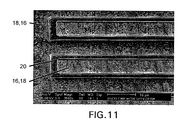
- Fig. 11 is a SEM image at 2500x magnification of a top view of a further alternate embodiment of a fuel cell structure 10 formed by a method(s) of the present invention.
- SSCO is one of the materials used to form the fuel cell 10 shown in Fig. 11.
- CVD Chemical Vapor Deposition
- PVD Physical Vapor Deposition
- spin coating atomic deposition
- atomic deposition and/or the like, and/or combinations thereof.
- the fuel cell 10 is sintered/annealed at temperatures ranging between about 200°C and about 1500°C. In an alternate embodiment, the fuel cell 10 is sintered/annealed at temperatures ranging between about 600°C and about 1100°C. It is to be understood that the temperature should be high enough to sinter the anode 16, cathode 18 and electrolyte 20, not lower than the operating temperature of the fuel cell 10, and not higher than any active fuel cell elements can withstand.
Landscapes
- Engineering & Computer Science (AREA)
- Manufacturing & Machinery (AREA)
- Chemical Kinetics & Catalysis (AREA)
- General Chemical & Material Sciences (AREA)
- Electrochemistry (AREA)
- Chemical & Material Sciences (AREA)
- Sustainable Development (AREA)
- Sustainable Energy (AREA)
- Life Sciences & Earth Sciences (AREA)
- Physics & Mathematics (AREA)
- Thermal Sciences (AREA)
- Fuel Cell (AREA)
- Inert Electrodes (AREA)
Applications Claiming Priority (2)
| Application Number | Priority Date | Filing Date | Title |
|---|---|---|---|
| US286235 | 2002-10-31 | ||
| US10/286,235 US7067215B2 (en) | 2002-10-31 | 2002-10-31 | Fuel cell and method of manufacturing same using chemical/mechanical planarization |
Publications (1)
| Publication Number | Publication Date |
|---|---|
| EP1416568A2 true EP1416568A2 (de) | 2004-05-06 |
Family
ID=32093579
Family Applications (1)
| Application Number | Title | Priority Date | Filing Date |
|---|---|---|---|
| EP03256774A Withdrawn EP1416568A2 (de) | 2002-10-31 | 2003-10-28 | Herstellungsverfahren von Brennstoffzellen mit Chemisch-mechanischer Planarisierung |
Country Status (6)
| Country | Link |
|---|---|
| US (1) | US7067215B2 (de) |
| EP (1) | EP1416568A2 (de) |
| JP (1) | JP2004152763A (de) |
| KR (1) | KR101026445B1 (de) |
| CA (1) | CA2444520A1 (de) |
| TW (1) | TW200423469A (de) |
Cited By (4)
| Publication number | Priority date | Publication date | Assignee | Title |
|---|---|---|---|---|
| WO2006058357A3 (de) * | 2004-12-03 | 2007-01-18 | Fotec Forschungs Und Technolog | Mikroreaktor, insbesondere brennstoffzelle und verfahren zur herstellung |
| EP1796192A1 (de) * | 2005-12-08 | 2007-06-13 | Postech Foundation | Festoxidbrennstoffzellenmodul, Brennstoffzellensystem damit und Herstellungsverfahren dafür |
| EP1979976A4 (de) * | 2006-01-19 | 2009-12-16 | Univ Leland Stanford Junior | Membranelektrodenanordnng in festoxid-brennstoffzellen |
| EP1784881A4 (de) * | 2004-06-30 | 2011-07-20 | Univ Leland Stanford Junior | Nanoröhren-festoxid-brennstoffzelle |
Families Citing this family (20)
| Publication number | Priority date | Publication date | Assignee | Title |
|---|---|---|---|---|
| CA2414622A1 (en) * | 2002-12-17 | 2004-06-17 | Alberta Research Council Inc. | Compact solid oxide fuel cell stack |
| US7670703B2 (en) * | 2003-10-15 | 2010-03-02 | Societe De Commercialisation Des Produits De La Recherche Appliquee Socpra Sciences Et Genie S.E.C. | Solid electrolyte fuel cell supported by an integrated reformer |
| US20050106436A1 (en) * | 2003-11-14 | 2005-05-19 | Dennis Lazaroff | Dual chamber fuel cell elements |
| CN1645661A (zh) * | 2004-01-20 | 2005-07-27 | 布莱特·D·文森特 | 燃料电池系统 |
| US7314772B2 (en) * | 2005-03-14 | 2008-01-01 | Hewlett-Packard Development Company, L.P. | Photonic device |
| KR100691558B1 (ko) * | 2005-04-22 | 2007-03-09 | 한국과학기술연구원 | 고체 산화물 연료전지의 제조 방법 |
| EP1889316B1 (de) * | 2005-05-31 | 2012-05-16 | Nissan Motor Co., Ltd. | Elektrolyt-membran-elektroden-baugruppe und zugehöriges herstellungsverfahren |
| KR100728781B1 (ko) * | 2005-07-27 | 2007-06-19 | 삼성에스디아이 주식회사 | 연료 전지용 막-전극 어셈블리 및 이를 포함하는 연료 전지시스템 |
| US7871734B2 (en) * | 2005-08-23 | 2011-01-18 | Massachusetts Institute Of Technology | Micro fuel cell |
| KR100707113B1 (ko) * | 2005-12-20 | 2007-04-16 | 한국과학기술연구원 | 고립 전해질을 이용한 단실형 고체 산화물 연료전지 |
| KR100735448B1 (ko) | 2006-03-07 | 2007-07-04 | 삼성전기주식회사 | Cmp 프로세스를 적용한 연료전지용 초소형 개질 기제조방법 |
| US8900771B2 (en) * | 2006-08-17 | 2014-12-02 | GM Global Technology Operations LLC | Non-noble metal inexpensive conductive coatings for fuel cell bipolar plates |
| US8691464B2 (en) * | 2007-05-25 | 2014-04-08 | Massachusetts Institute Of Technology | Three dimensional single-chamber fuel cells |
| KR101006467B1 (ko) * | 2008-01-31 | 2011-01-06 | 포항공과대학교 산학협력단 | 고체산화물 연료전지용 전극 지지체와 일체형 단위 셀 및그 제조 방법 |
| US8906534B2 (en) * | 2008-05-28 | 2014-12-09 | Taiwan Semiconductor Manufacturing Company, Ltd. | Stacked multi-cell battery concept |
| TWI472090B (zh) | 2011-04-22 | 2015-02-01 | Univ Nat Cheng Kung | Fuel cell solid electrolyte structure |
| JP5590181B2 (ja) * | 2013-04-11 | 2014-09-17 | 日産自動車株式会社 | 燃料電池 |
| WO2015054065A1 (en) | 2013-10-08 | 2015-04-16 | Phillips 66 Company | Liquid phase modification of electrodes of solid oxide fuel cells |
| WO2015054024A1 (en) | 2013-10-08 | 2015-04-16 | Phillips 66 Company | Gas phase modification of solid oxide fuel cells |
| US10418657B2 (en) | 2013-10-08 | 2019-09-17 | Phillips 66 Company | Formation of solid oxide fuel cells by spraying |
Family Cites Families (13)
| Publication number | Priority date | Publication date | Assignee | Title |
|---|---|---|---|---|
| US4248941A (en) * | 1979-12-26 | 1981-02-03 | United Tecnologies Corporation | Solid electrolyte electrochemical cell |
| US4749632A (en) * | 1986-10-23 | 1988-06-07 | The United States Of America As Represented By The United States Department Of Energy | Sintering aid for lanthanum chromite refractories |
| US4799936A (en) * | 1987-06-19 | 1989-01-24 | Combustion Engineering, Inc. | Process of forming conductive oxide layers in solid oxide fuel cells |
| US4883497A (en) * | 1988-03-28 | 1989-11-28 | Arch Development Corporation | Formation of thin walled ceramic solid oxide fuel cells |
| JPH08143909A (ja) * | 1994-11-21 | 1996-06-04 | Toshiba Corp | 燃料電池電極用粉体散布成形装置 |
| JPH08195216A (ja) * | 1995-01-18 | 1996-07-30 | Fuji Electric Co Ltd | 固体電解質型燃料電池の製造方法 |
| JP2000353532A (ja) * | 1999-06-11 | 2000-12-19 | Daihatsu Motor Co Ltd | 金属体の表面処理方法、および燃料電池に用いられるプレートの表面処理方法 |
| US6649031B1 (en) * | 1999-10-08 | 2003-11-18 | Hybrid Power Generation Systems, Llc | Corrosion resistant coated fuel cell bipolar plate with filled-in fine scale porosities and method of making the same |
| US6645656B1 (en) * | 2000-03-24 | 2003-11-11 | University Of Houston | Thin film solid oxide fuel cell and method for forming |
| US6835488B2 (en) * | 2000-05-08 | 2004-12-28 | Honda Giken Kogyo Kabushiki Kaisha | Fuel cell with patterned electrolyte/electrode interface |
| JP4196374B2 (ja) * | 2001-03-29 | 2008-12-17 | パナソニック株式会社 | 高分子電解質型薄膜燃料電池およびその運転方法 |
| US6677070B2 (en) * | 2001-04-19 | 2004-01-13 | Hewlett-Packard Development Company, L.P. | Hybrid thin film/thick film solid oxide fuel cell and method of manufacturing the same |
| US6611085B1 (en) * | 2001-08-27 | 2003-08-26 | Sandia Corporation | Photonically engineered incandescent emitter |
-
2002
- 2002-10-31 US US10/286,235 patent/US7067215B2/en not_active Expired - Lifetime
-
2003
- 2003-09-09 TW TW092124885A patent/TW200423469A/zh unknown
- 2003-10-09 CA CA002444520A patent/CA2444520A1/en not_active Abandoned
- 2003-10-27 JP JP2003365696A patent/JP2004152763A/ja active Pending
- 2003-10-28 EP EP03256774A patent/EP1416568A2/de not_active Withdrawn
- 2003-10-31 KR KR1020030076792A patent/KR101026445B1/ko not_active Expired - Fee Related
Cited By (6)
| Publication number | Priority date | Publication date | Assignee | Title |
|---|---|---|---|---|
| EP1784881A4 (de) * | 2004-06-30 | 2011-07-20 | Univ Leland Stanford Junior | Nanoröhren-festoxid-brennstoffzelle |
| WO2006058357A3 (de) * | 2004-12-03 | 2007-01-18 | Fotec Forschungs Und Technolog | Mikroreaktor, insbesondere brennstoffzelle und verfahren zur herstellung |
| EP1796192A1 (de) * | 2005-12-08 | 2007-06-13 | Postech Foundation | Festoxidbrennstoffzellenmodul, Brennstoffzellensystem damit und Herstellungsverfahren dafür |
| US7947386B2 (en) | 2005-12-08 | 2011-05-24 | Postech Foundation | Solid oxide fuel cell module, fuel cell system using the same and manufacturing method thereof |
| CN1979938B (zh) * | 2005-12-08 | 2013-10-16 | 学校法人浦项工科大学校 | 固体氧化物燃料电池组件、使用其的燃料电池系统及其制造方法 |
| EP1979976A4 (de) * | 2006-01-19 | 2009-12-16 | Univ Leland Stanford Junior | Membranelektrodenanordnng in festoxid-brennstoffzellen |
Also Published As
| Publication number | Publication date |
|---|---|
| US7067215B2 (en) | 2006-06-27 |
| US20040086754A1 (en) | 2004-05-06 |
| KR101026445B1 (ko) | 2011-04-07 |
| JP2004152763A (ja) | 2004-05-27 |
| TW200423469A (en) | 2004-11-01 |
| CA2444520A1 (en) | 2004-04-30 |
| KR20040038874A (ko) | 2004-05-08 |
Similar Documents
| Publication | Publication Date | Title |
|---|---|---|
| US7067215B2 (en) | Fuel cell and method of manufacturing same using chemical/mechanical planarization | |
| EP1380065B1 (de) | Festoxid-brennstoffzelle in hybrid-dickschicht-dünnschichttechnik und verfahren zu ihrer herstellung | |
| EP1434297B1 (de) | Brennstoffzelle mit eingebettetem Stromabnehmer | |
| Evans et al. | Review on microfabricated micro-solid oxide fuel cell membranes | |
| US6645656B1 (en) | Thin film solid oxide fuel cell and method for forming | |
| US7445814B2 (en) | Methods of making porous cermet and ceramic films | |
| US20070184322A1 (en) | Membrane electrode assembly in solid oxide fuel cells | |
| EP1327279A2 (de) | Integrierte festoxid-brennstoffzelle | |
| AU2001284851A1 (en) | Integrated sofc | |
| US20110262839A1 (en) | Proton conducting electrolyte membranes having nano-grain ysz as protective layers, and membrane electrode assemblies and ceramic fuel cells comprising same | |
| JP4824916B2 (ja) | 電流コレクタ支持型燃料電池 | |
| KR20070027741A (ko) | 서브미크론 고체산화물 전해막 | |
| AU2003229677B2 (en) | High-temperature solid electrolyte fuel cell comprising a composite of nanoporous thin-film electrodes and a structured electrolyte | |
| KR20070026859A (ko) | 서브미크론 고체산화물 전해막의 제조방법 | |
| US10483578B2 (en) | Method for manufacturing anode support of solid oxide fuel cell, and anode support of solid oxide fuel cell | |
| Minh | Honeywell Engines, Systems & Services |
Legal Events
| Date | Code | Title | Description |
|---|---|---|---|
| PUAI | Public reference made under article 153(3) epc to a published international application that has entered the european phase |
Free format text: ORIGINAL CODE: 0009012 |
|
| AK | Designated contracting states |
Kind code of ref document: A2 Designated state(s): AT BE BG CH CY CZ DE DK EE ES FI FR GB GR HU IE IT LI LU MC NL PT RO SE SI SK TR |
|
| AX | Request for extension of the european patent |
Extension state: AL LT LV MK |
|
| STAA | Information on the status of an ep patent application or granted ep patent |
Free format text: STATUS: THE APPLICATION HAS BEEN WITHDRAWN |
|
| 18W | Application withdrawn |
Effective date: 20060124 |