EP1416599B1 - Bougie d'allumage et sa méthode de fabrication - Google Patents
Bougie d'allumage et sa méthode de fabrication Download PDFInfo
- Publication number
- EP1416599B1 EP1416599B1 EP03256898A EP03256898A EP1416599B1 EP 1416599 B1 EP1416599 B1 EP 1416599B1 EP 03256898 A EP03256898 A EP 03256898A EP 03256898 A EP03256898 A EP 03256898A EP 1416599 B1 EP1416599 B1 EP 1416599B1
- Authority
- EP
- European Patent Office
- Prior art keywords
- electrode
- chip
- face
- flange portion
- base metal
- Prior art date
- Legal status (The legal status is an assumption and is not a legal conclusion. Google has not performed a legal analysis and makes no representation as to the accuracy of the status listed.)
- Expired - Lifetime
Links
- 238000000034 method Methods 0.000 title claims description 32
- 238000004519 manufacturing process Methods 0.000 title claims description 27
- 239000010953 base metal Substances 0.000 claims description 77
- 238000003466 welding Methods 0.000 claims description 45
- 239000012212 insulator Substances 0.000 claims description 32
- 238000005304 joining Methods 0.000 claims description 22
- 239000000463 material Substances 0.000 claims description 8
- 238000009760 electrical discharge machining Methods 0.000 claims description 6
- 238000002844 melting Methods 0.000 claims description 3
- 230000008018 melting Effects 0.000 claims description 3
- 230000035515 penetration Effects 0.000 description 8
- 230000008646 thermal stress Effects 0.000 description 6
- 229910000990 Ni alloy Inorganic materials 0.000 description 4
- 229910001026 inconel Inorganic materials 0.000 description 4
- 230000007774 longterm Effects 0.000 description 3
- 229910000575 Ir alloy Inorganic materials 0.000 description 2
- 229910001260 Pt alloy Inorganic materials 0.000 description 2
- 229910045601 alloy Inorganic materials 0.000 description 2
- 239000000956 alloy Substances 0.000 description 2
- 230000000694 effects Effects 0.000 description 2
- 238000000926 separation method Methods 0.000 description 2
- 229910000640 Fe alloy Inorganic materials 0.000 description 1
- 230000007547 defect Effects 0.000 description 1
- 238000010586 diagram Methods 0.000 description 1
- 238000004299 exfoliation Methods 0.000 description 1
Images





Classifications
-
- H—ELECTRICITY
- H01—ELECTRIC ELEMENTS
- H01T—SPARK GAPS; OVERVOLTAGE ARRESTERS USING SPARK GAPS; SPARKING PLUGS; CORONA DEVICES; GENERATING IONS TO BE INTRODUCED INTO NON-ENCLOSED GASES
- H01T21/00—Apparatus or processes specially adapted for the manufacture or maintenance of spark gaps or sparking plugs
- H01T21/02—Apparatus or processes specially adapted for the manufacture or maintenance of spark gaps or sparking plugs of sparking plugs
-
- H—ELECTRICITY
- H01—ELECTRIC ELEMENTS
- H01T—SPARK GAPS; OVERVOLTAGE ARRESTERS USING SPARK GAPS; SPARKING PLUGS; CORONA DEVICES; GENERATING IONS TO BE INTRODUCED INTO NON-ENCLOSED GASES
- H01T13/00—Sparking plugs
- H01T13/20—Sparking plugs characterised by features of the electrodes or insulation
- H01T13/39—Selection of materials for electrodes
Definitions
- the present invention relates to a spark plug and the method for manufacturing the same.
- Patent Document 1 describes a conventionally known spark plug.
- This spark plug includes a tubular metallic shell.
- a tubular insulator is fixed in the metallic shell in such a manner as to extend in the axial direction of the metallic shell and such that the opposite ends of the insulator protrude from corresponding opposite ends of the metallic shell.
- a center electrode extends in the axial direction of the metallic shell such that the distal end of the center electrode protrudes from the distal end of the insulator, and the rear end of the center electrode is fixed in the insulator.
- Each of the center electrode and the ground electrode includes an electrode base metal, which is an Ni alloy or the like such as Inconel (registered trademark) 600, and a chip provided on the electrode base metal at a position for forming the discharge gap and formed of a spark erosion resistant material such as an Ir-containing Pt alloy.
- the center electrode of this spark plug is manufactured as follows. First there is formed a chip which includes a flange portion and a protrusion protruding from a first face of the flange portion. A second face of the chip opposite the protrusion is laser welded to a joint face of the electrode base metal located on the side toward the discharge gap, thereby forming the center electrode. At this time, a weld portion is formed in such a manner as to penetrate into the electrode base metal and the flange portion of the chip.
- the diameter of the flange portion of the chip is greater than that of the protrusion of the chip.
- a weld portion is formed over a wide range. Since a weld portion is formed in such a manner as to penetrate into the flange portion and the electrode base metal, there can be prevented a reduction in the diameter of a weld zone, which would otherwise result from spattering of the electrode base metal induced by laser welding.
- this spark plug can ensure the joining strength between the electrode base metal and the chip.
- Patent Document 1 which discloses the above-described conventional spark plug, merely specifies that the weld portion be present over a certain distance or more as measured inward from the outer circumference of the flange portion of the chip.
- difficulty may be encountered in ensuring the joining strength between the electrode base metal and the chip.
- an employed chip includes a flange portion and a columnar protrusion, and the diameter of the protrusion is relatively large, a weld portion is formed only in the vicinity of the outer circumference of the flange portion, and thus the weld portion is not present in a large area at a central part of the flange portion.
- sufficient joining strength between the electrode base metal and the chip fails to be ensured, and difficulty is encountered in maintaining the durability of the spark plug over a long term.
- the present invention has been accomplished in view of the above-mentioned problems involved in the conventional spark plug, and an object of the invention is to provide a spark plug whose joining strength between an electrode base metal and a chip is reliably ensured, as well as to provide a method for manufacturing the same.
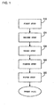
- the present invention provides a method for manufacturing a spark plug which comprises a tubular metallic shell, a tubular insulator extending in an axial direction of the metallic shell and fixed in the metallic shell with opposite ends of the insulator protruding from corresponding opposite ends of the metallic shell, a center electrode extending in the axial direction of the metallic shell and fixed in the insulator with a distal end of the center electrode protruding from a distal end of the insulator and with a rear end of the center electrode fixed in the insulator, and a ground electrode with one end of the ground electrode fixed to the metallic shell and with the other end portion of the ground electrode and the center electrode forming a discharge gap therebetween, and in which at least either one of the center electrode and the ground electrode comprises an electrode base metal and a chip provided on the electrode base metal at a position for forming the discharge gap and formed of a spark erosion resistant material, the method comprising:
- the chip comprising the flange portion and the protrusion protruding from the first face of the flange portion is provided (for example by being manufactured).
- the second face of the flange portion is tentatively joined, through resistance welding, to the joint face of the electrode base metal of at least either one of the center electrode and the ground electrode, the joint face being located on the side toward the discharge gap.
- the flange portion is laser-welded to the joint face of the electrode base metal.
- the laser welding is performed such that the weld portion is formed between the electrode base metal and the chip to reach points on the second face of the flange portion, the points being inward of corresponding intersections of the second face of the flange portion and imaginary extension lines of generatrices of the side surface of the protrusion.
- the protrusion of the chip assumes the shape of a cylinder, a prism, a circular cone, a pyramid, a frustum of a cone, or a frustum of a pyramid
- the generatrices are lines extending on the side surface of the protrusion and capable of forming a common plane together with the axis of the protrusion.
- the method for manufacturing a spark plug of the present invention can ensure sufficient joining strength between the electrode base metal and the chip.
- the method for manufacturing a spark plug of the present invention allows the joint face to be located on the electrode base metal of the ground electrode on the side toward the discharge gap.
- the method can be applied not only to the case of welding the chip to the electrode base metal of the center electrode, but also to the case of welding the chip to the electrode base metal of the ground electrode, which requires higher welding strength.
- the weld portion is present in such a manner as to extend to a distance D/5 or more inward of the intersections as measured on the second face.
- a plate-like intermediate member having a melting point or linear expansion coefficient falling between that of the electrode base metal and that of the chip, and having a face larger than the second face of the flange portion; and in the second step, the intermediate member is provided between the joint face and the chip.
- the intermediate member provides good compatibility between the intermediate member and the electrode base metal and that between the intermediate member and the chip and reduces the difference in thermal stress to be induced between the intermediate member and the electrode base metal and that between the intermediate member and the chip. Therefore, separation hardly arises between the intermediate member and the electrode base metal and between the intermediate member and the chip.
- the second face of the flange portion is tentatively joined to the intermediate member through resistance welding. This prevents movement of the intermediate member and the chip during the course of laser welding, thereby reliably welding the electrode base metal and the chip.
- the chip when the joint face is located on the electrode base metal of the ground electrode on the side toward the discharge gap, the chip is welded to the ground electrode while the ground electrode is bent away from the distal end of the center electrode. Since this avoids imposition of restrictions on the angle of laser irradiation, the chip can be welded to the ground electrode at the optimum angle of laser irradiation.
- the present invention provides a spark plug comprising a tubular metallic shell, a tubular insulator extending in an axial direction of the metallic shell and fixed in the metallic shell with opposite ends of the insulator protruding from corresponding opposite ends of the metallic shell, a center electrode extending in the axial direction of the metallic shell and fixed in the insulator with a distal end of the center electrode protruding from a distal end of the insulator and with a rear end of the center electrode fixed in the insulator, and a ground electrode with one end of the ground electrode fixed to the metallic shell and with the other end portion of the ground electrode and the center electrode forming a discharge gap therebetween, at least either one of the center electrode and the ground electrode comprising an electrode base metal and a chip provided on the electrode base metal at a position for forming the discharge gap and formed of a spark erosion resistant material, wherein the chip comprises a flange portion and a protrusion protruding from a first face of the flange portion; a second face of the
- the chip comprises the flange portion and the protrusion, and laser welding is performed such that the weld portion is formed between the electrode base metal and the chip to reach points on the second face of the flange portion, the points being located inward of corresponding intersections of the second face of the flange portion and imaginary extension lines of generatrices of the side surface of the protrusion.
- the weld portion is not present in a large area at a central part of the flange portion. Therefore, the flange portion is reliably joined to the joint face of the electrode base metal, whereby the joining strength between the electrode base metal and the chip can be ensured, and the durability of the spark plug can be maintained over a long term.
- the weld portion contains components of the chip in an amount of 20% by mass to 80% by mass.
- the electrode base metal and the chip are unlikely to be compatible with each other, and a great difference arises in thermal stress to be induced between the electrode base metal and the chip, potentially resulting in a failure to ensure the joining strength between the electrode base metal and the chip.
- the weld portion contains components of the chip in an amount of 20% by mass to 80% by mass, the electrode base metal and the chip are compatible with each other, and the difference in thermal stress to be induced between the electrode base metal and the chip is small, whereby the joining strength between the electrode base metal and the chip can be readily ensured.
- the weld portion contains components of the chip in an amount of 30% by mass to 60% by mass. This reliably ensures the joining strength between the electrode base metal and the chip.
- a spark plug and a method for manufacturing the same according to an embodiment of the present invention and a test for the spark plug and the method will be described with reference to Figs. 1 to 10 .
- a chip 1 is manufactured from a spark erosion resistant material, which is an Ir alloy containing at least any one of 1% by mass to 20% by mass Rh, 1% by mass to 10% by mass Pt, 1% by mass to 5% by mass Y 2 O 3 , and 1% by mass to 20% by mass Ni, or a Pt alloy containing at least any one of 20% by mass to 60% by mass Rh, 10% by mass to 40% by mass Ir, and 1% by mass to 20% by mass Ni.
- a spark erosion resistant material which is an Ir alloy containing at least any one of 1% by mass to 20% by mass Rh, 1% by mass to 10% by mass Pt, 1% by mass to 5% by mass Y 2 O 3 , and 1% by mass to 20% by mass Ni, or a Pt alloy containing at least any one of 20% by mass to 60% by mass Rh, 10% by mass to 40% by mass Ir, and 1% by mass to 20% by mass Ni.
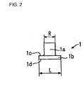
- the chip 1 includes a flange portion 1b and a protrusion 1 a protruding from a first face 1c of the flange portion 1b.
- the flange portion 1b assumes the shape of a disk and has a diameter L of 1 mm and a thickness of 0.2 mm.
- the protrusion 1a assumes a cylindrical shape and has a diameter R of 0.6 mm and a thickness of 0.5 mm.
- an intermediate member 2 is manufactured from an Ir alloy containing 40% by mass Ni.
- the intermediate member 2 assumes the shape of a disk and has a diameter L of 1.2 mm and a thickness of 0.2 mm.
- the intermediate member 2 is tentatively joined to the center electrode 30 through resistance welding.
- the center electrode 30 uses Inconel (registered trademark) 600, which is an Ni alloy, as an electrode base metal and has a diameter of 2.5 mm.
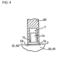
- the intermediate member 2 is placed on a joint face 32 of the center electrode 30, the joint face 32 facing a discharge gap. Then, a first electric resistance welding machine 50 is applied to the intermediate member 2. A predetermined current is applied to the first electric resistance welding machine 50 while a predetermined pressure is applied to the intermediate member 2, thereby tentatively joining the intermediate member 2 to the center electrode 30 through resistance welding.
- the flange portion 1b of the chip 1 is placed on the intermediate member 2, which is tentatively joined to the center electrode 30.
- a second electric resistance welding machine 60 is applied to the first face 1c of the flange portion 1b.
- a predetermined current is applied to the second electric resistance welding machine 60 while a predetermined pressure is applied to the first face 1 c.
- the second electric resistance welding machine 60 assumes such a structure as not to come into contact with the distal end face of the chip 1, whereby the distal end face of the chip 1 is free of any influence of the resistance welding.
- a second face 1 d of the flange portion 1b is tentatively joined to the intermediate member 2 through resistance welding, whereby the intermediate member 2 and the chip 1 are tentatively joined to the center electrode 30.
- a laser beam is irradiated so as to weld the flange portion 1b of the chip 1 to the joint face 32 of the center electrode 30.
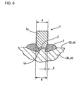
- the laser welding is performed such that, as shown in Fig. 6 , when D represents the maximum distance between the intersections of the second face 1d of the flange portion 1b and imaginary extension lines of generatrices extending on the side surface of the cylindrical protrusion 1a and capable of forming a common plane together with the axis of the protrusion 1a, and a represents the distance of the deepest point of a weld portion 3 as measured on the second face 1d from the intersection, a is D/5 or more.
- D is equal to the diameter R of the protrusion 1.
- the center electrode 30 is fitted into an insulator 62 such that the distal end of the center electrode 30 protrudes from the insulator 62; and a terminal 63 is inserted into the insulator 62 to be located on the rear side of the center electrode 30.
- the resultant assembly is fitted into a metallic shell 60.
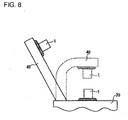
- the ground electrode 40 which is welded to the metallic shell 60 beforehand, is prepared.
- the ground electrode 40 uses Inconel (registered trademark) 600, which is an Ni alloy, as an electrode base metal and has a width of 2.5 mm.
- the ground electrode 40 is bent away from the distal end of the center electrode 30.
- the intermediate member 2 is tentatively joined to the ground electrode 40 through resistance welding.
- the intermediate member 2 is placed on a joint face 42 of the ground electrode 40, the joint face 42 facing the discharge gap. Then, the first electric resistance welding machine 50 is applied to the intermediate member 2. A predetermined current is applied to the first electric resistance welding machine 50 while a predetermined pressure is applied to the intermediate member 2, thereby tentatively joining the intermediate member 2 to the ground electrode 40 through resistance welding.
- the flange portion 1b of the chip 1 is placed on the intermediate member 2, which is tentatively joined to the ground electrode 40.
- the second electric resistance welding machine 60 is applied to the first face 1c of the flange portion 1b.
- a predetermined current is applied to the second electric resistance welding machine 60 while a predetermined pressure is applied to the first face 1c, thereby tentatively joining the second face 1d of the flange portion 1b to the intermediate member 2 through resistance welding.
- the intermediate member 2 and the chip 1 are tentatively joined to the ground electrode 40.
- a laser beam is irradiated so as to weld the flange portion 1b of the chip 1 to the joint face 42 of the ground electrode 40.
- the laser welding is performed such that, as shown in Fig. 6 , when D represents the maximum distance between the intersections of the second face 1d of the flange portion 1b and imaginary extension lines of generatrices extending on the side surface of the cylindrical protrusion 1a and capable of forming a common plane together with the axis of the protrusion 1a, and a represents the distance of the deepest point of the weld portion 3 as measured on the second face 1d from the intersection, a is D/5 or more.
- D is equal to the diameter R of the protrusion 1.
- the weld portion 3 is present in such a manner as to extend to a distance D/5 or more inward of the intersections as measured on the second face.
- the weld portion 3 is not present in a large area at a central part of the flange portion 1b. Therefore, the flange portion 1b is reliably joined to the joint face 32 (42) of the electrode base metal.
- the intermediate member 2 has a melting point and a linear expansion coefficient falling between those of the electrode base metal and those of the chip 1; thus, during the course of laser irradiation, good compatibility is established between the intermediate member 2 and the electrode base metal and between the intermediate member 2 and the chip 1, and the difference in thermal stress to be induced between the intermediate member 2 and the electrode base metal and that between the intermediate member 2 and the chip 1 can be reduced. Therefore, separation hardly arises between the intermediate member 2 and the electrode base metal and between the intermediate member 2 and the chip 1.
- the intermediate member 2 is tentatively joined to the joint face 32 (42) through resistance welding
- the second face 1d of the flange portion 1b is tentatively joined to the intermediate member 2 through resistance welding; thus, movement of the intermediate member 2 and the chip 1 during the course of laser welding can be prevented, whereby the electrode base metal and the chip 1 can be reliably welded together.
- the method for manufacturing a spark plug of the present embodiment can reliably ensure the joining strength between the electrode base metal and the chip 1.
- the chip 1 is welded to the ground electrode 40 while the ground electrode 40 is bent away from the distal end of the center electrode 30. Since this avoids imposition of restrictions on the angle of laser irradiation, the chip 1 can be welded to the ground electrode 40 at the optimum angle of laser irradiation.
- the thus-obtained spark plug includes the tubular metallic shell 60.
- the tubular insulator 62 is fixed in the metallic shell 60 in such a manner as to extend in the axial direction of the metallic shell 60 and such that the opposite ends of the insulator 62 protrude from corresponding opposite ends of the metallic shell 60.
- the center electrode 30 extends in the axial direction of the metallic shell 60 such that the distal end of the center electrode 30 protrudes from the distal end of the insulator 62, and the rear end of the center electrode 30 is fixed in the insulator 62.
- one end of the ground electrode 40 is fixed to the metallic shell 60, and the other end portion of the ground electrode 40, together with the center electrode 30, forms a discharge gap therebetween.
- the chips 1 are provided on the center electrode 30 and the ground electrode 40, respectively, in opposition to each other while maintaining a discharge gap therebetween.
- the chip 1 includes the flange portion 1b and the protrusion 1a.
- the chip 1 is laser-welded to the electrode base metal such that the weld portion 3 is formed between the electrode base metal and the chip 1 and reaches points on the second face 1d of the flange portion 1b, the points being located inward of corresponding intersections of the second face 1d of the flange portion 1b and imaginary extension lines of generatrices extending on the side surface of the cylindrical protrusion 1a and capable of forming a common plane together with the axis of the protrusion 1 a.
- the weld portion 3 is not present in a large area at a central part of the flange portion 1b. Therefore, the flange portion 1b is reliably joined to the joint face 32 (42) of the electrode base metal, whereby the joining strength between the electrode base metal and the chip 1 can be ensured, and the durability of the spark plug can be maintained over a long term.
- the weld portion 3 contains components of the chip 1 in an amount of 30% by mass to 60% by mass, the electrode base metal and the chip 1 are compatible with each other, and the difference in thermal stress to be induced between the electrode base metal and the chip 1 is small, whereby the joining strength between the electrode base metal and the chip 1 can be readily ensured.
- the chips 1 and the intermediate members 2 were manufactured by use of alloys similar to those of the embodiment and in shapes similar to those of the embodiment. Four types of the chips 1 were manufactured as follows: as shown in Fig.
- D represents the maximum distance (equal to the diameter R of the protrusion 1; hereinafter called the "diameter R of the protrusion 1" between intersections of the second face 1d of the flange portion 1b and imaginary extension lines of generatrices extending on the side surface of the cylindrical protrusion 1a and capable of forming a common plane together with the axis of the protrusion 1a
- D is 0.6 mm, 0.8 mm, 1.0 mm, and 1.2 mm.
- the diameter of the flange portion 1b is 0.4 mm greater than the diameter R of the protrusion 1 of each type.
- Each of the chips 1 was laser-welded, in a manner similar to that of the embodiment, to an electrode base metal that was an alloy similar to that used to form the center electrode 30 and the ground electrode 40 of the embodiment.
- the test was conducted for the following two cases: the intermediate member 2 was used as in the case of the embodiment; and, without use of the intermediate member 2, the chip 1 was directly laser-welded to the electrode base metal.
- the test conditions are described below.
- the chip 1 was laser-welded to the electrode base metal as follows: when a represents the distance of the deepest point (hereinafter, called "penetration") of the weld portion 3 as measured on the second face 1 d from the intersection between the second face 1d of the flange portion 1b and an imaginary extension line of a generatrix of the side surface of the protrusion 1a, the weld portion 3 of a predetermined penetration a was formed for each type of the chip 1.
- the weld portion was heated for two minutes by use of a burner and was then allowed to cool at the room temperature for one minute. After this cycle was repeated for 50 hours, the weld portion was examined for the length of an oxide scale.
- the oxide scale refers to a defect induced by a difference in thermal stress; specifically, a crack observed on the cross section of the chip 1 or exfoliation of the chip 1.
- the burner temperature was 900°C and 950°C.
- Tables 1 to 4 show the test results.
- Table 1 shows the test results for a diameter R of the protrusion 1 of 0.6 mm;
- Table 2 shows the test results for a diameter R of the protrusion 1 of 0.8 mm;
- Table 3 shows the test results for a diameter R of the protrusion 1 of 1.0 mm;
- Table 4 shows the test results for a diameter R of the protrusion 1 of 1.2 mm.
- "o" indicates that the length b of an oxide scale is less than L/3, where L is the diameter of the flange portion 1b;
- ⁇ indicates that the length b of an oxide scale is equal to or greater than L/3 and less than L/2; and
- ⁇ indicates that the length b of an oxide scale is equal to or greater than L/2.
- the manufacturing method of the embodiment can employ chips in various shapes; for example, chips 71 to 73 shown in Figs. 10(a) to 10(c) .
- a protrusion 71a has a taper surface.
- a flange portion 72b has a taper surface.
- a protrusion 73a has a taper surface, and the diameter of a bottom surface 73c of the protrusion 73a is equal to that of the flange portion 72b. Even when these chips 71 to 73 are used, the effect of the present invention can be yielded.
- both of the protrusion and the flange portion assume a circular shape.
- the present invention is not limited thereto.
- a polygonal (e.g., triangular or quadrangular) chip may be used.
- the protrusion and the flange portion do not necessarily assume the same shape.
- the center electrode and the ground electrode use Inconel (registered trademark) as an electrode base metal.
- the electrode base metal may be, for example, Ni, an Ni alloy, Fe, or an Fe alloy.
Landscapes
- Engineering & Computer Science (AREA)
- Manufacturing & Machinery (AREA)
- Spark Plugs (AREA)
Claims (9)
- Procédé pour fabriquer une bougie d'allumage qui comprend une enveloppe métallique tubulaire (60), un isolateur tubulaire (62) s'étendant dans une direction axiale de l'enveloppe métallique (60) et fixé dans l'enveloppe métallique (60) avec des extrémités opposées de l'isolateur (62) qui font saillie à partir d'extrémités opposées correspondantes de l'enveloppe métallique (60), une électrode centrale (30) s'étendant dans la direction axiale de l'enveloppe métallique (60) et fixée dans l'isolateur (62) avec une extrémité distale de l'électrode centrale (30) qui fait saillie à partir d'une extrémité distale de l'isolateur (62) et avec une extrémité arrière de l'électrode centrale (30) fixée dans l'isolateur (62), et une électrode de masse (40) avec une extrémité de l'électrode de masse (40) fixée à l'enveloppe métallique (60) et avec l'autre partie d'extrémité de l'électrode de masse (40) et l'électrode centrale (30) qui forment un espace de décharge entre elles, au moins l'une de l'électrode centrale (30) et de l'électrode de masse (40) comprenant un métal de base d'électrode et une pastille (1) disposée sur le métal de base d'électrode en une position permettant de former l'espace de décharge et constituée par un matériau résistant à l'érosion par les étincelles, caractérisé en ce que le procédé comprend :une première étape consistant à disposer la pastille (1), qui comprend une partie de flasque (1b) et une saillie (1a) faisant saillie à partir d'une première face (1c) de la partie de flasque ;une deuxième étape consistant à tenter de réunir, par soudage résistif, une deuxième face (1d) de la partie de flasque (1b) opposée à la saillie (1a) à une surface de réunion (32/42) du métal de base d'électrode d'au moins l'une ou l'autre de l'électrode centrale (30) et de l'électrode de masse (40), la face de réunion (32/42) étant située sur un côté dirigé vers l'espace de décharge ; etune troisième étape consistant à souder au laser la partie de flasque (1b) à la face de réunion (32/42) de telle sorte qu'une partie de soudage (3) soit formée entre le métal de base d'électrode et la pastille, de façon à atteindre des points sur la deuxième face (1d) de la partie de flasque (1b), les points étant situés à l'intérieur d'intersections correspondantes de la deuxième face (1d) de la partie de flasque (1b) et de lignes d'extension imaginaires de génératrices d'une surface latérale de la saillie (1a).
- Procédé pour fabriquer une bougie d'allumage selon la revendication 1, dans lequel la face de réunion (32/42) est située sur le métal de base d'électrode de l'électrode de masse (40) sur un côté dirigé vers l'espace de décharge.
- Procédé pour fabriquer une bougie d'allumage selon la revendication 2, dans lequel, lorsque D représente une distance maximale entre les intersections, la partie de soudage (3) est présente de façon à s'étendre jusqu'à une distance de D/5 ou plus vers l'intérieur des intersections, mesurée sur la deuxième face.
- Procédé pour fabriquer une bougie d'allumage selon l'une quelconque des revendications 1 à 3, dans lequel la première étape comprend de plus la disposition d'un élément intermédiaire en forme de plaque (2) ayant au moins l'un parmi un point de fusion et un coefficient de dilatation linéaire compris entre ceux du métal de base d'électrode et ceux de la pastille (1), et ayant une face plus grande que la deuxième face (1d) de la partie de flasque (1b) ; et
la deuxième étape comprend de plus la disposition de l'élément intermédiaire (2) entre la face de réunion (32/42) et la pastille (1). - Procédé pour fabriquer une bougie d'allumage selon la revendication 4, dans lequel la deuxième étape comprend de plus, après la tentative de réunion de l'élément intermédiaire (2) à la face de réunion (32/42) par soudage résistif, une tentative de réunion de la deuxième face (1d) de la partie de flasque (1b) à l'élément intermédiaire (2) par soudage résistif.
- Procédé pour fabriquer une bougie d'allumage selon l'une quelconque des revendications 1 à 5, comprenant de plus la disposition de la face de réunion (32/42) sur le métal de base d'électrode de l'électrode de masse (40) sur un côté dirigé vers l'espace de décharge, et le soudage de la pastille (1) à l'électrode de masse (40) tandis que l'électrode de masse (40) est incurvée de façon à l'éloigner de l'extrémité distale de l'électrode centrale (30).
- Bougie d'allumage comprenant une enveloppe métallique tubulaire (60), un isolateur tubulaire (62) s'étendant dans une direction axiale de l'enveloppe métallique (60) et fixé dans l'enveloppe métallique (60) avec des extrémités opposées de l'isolateur (62) qui font saillie à partir d'extrémités opposées correspondantes de l'enveloppe métallique (60), une électrode centrale (30) s'étendant dans la direction axiale de l'enveloppe métallique (60) et fixée dans l'isolateur (62) avec une extrémité distale de l'électrode centrale (30) qui fait saillie à partir d'une extrémité distale de l'isolateur (62) et avec une extrémité arrière de l'électrode centrale (30) fixée dans l'isolateur (62), et une électrode de masse (40) avec une extrémité de l'électrode de masse (40) fixée à l'enveloppe métallique (60) et avec l'autre partie d'extrémité de l'électrode de masse (40) et l'électrode centrale (30) qui forment un espace de décharge entre elles, au moins l'une de l'électrode centrale (30) et de l'électrode de masse (40) comprenant un métal de base d'électrode et une pastille (1) disposée sur le métal de base d'électrode en une position permettant de former l'espace de décharge et constituée par un matériau résistant à l'érosion par les étincelles, caractérisée en ce que :la pastille (1) comprend une partie de flasque (1b) et une saillie (1a) faisant saillie à partir d'une première face (1c) de la partie de flasque (1b) ;on tente de réunir, par soudage résistif, une deuxième face (1d) de la partie de flasque (1b), opposée à la saillie (la), à une face de réunion (32/42) du métal de base d'électrode d'au moins l'une ou l'autre de l'électrode centrale (30) et de l'électrode de masse (40), la face de réunion (32/42) étant située sur un côté dirigé vers l'espace de décharge ; etla partie de flasque (1b) est soudée au laser à la face de réunion (32/42) de telle sorte qu'une partie de soudure (3) soit formée entre le métal de base d'électrode et la pastille (1) de façon à atteindre des points sur la deuxième face (1d) de la partie de flasque (1b), les points étant situés vers l'intérieur d'intersections correspondantes de la deuxième face (1d) de la partie de flasque (1b) et de lignes d'extension imaginaires de génératrices d'une surface latérale de la saillie (1a).
- Bougie d'allumage selon la revendication 7, dans laquelle la partie de soudure (3) contient des composants de la pastille (1) sous une quantité située dans la plage comprise entre 20% en masse et 80% en masse.
- Bougie d'allumage selon la revendication 8, dans laquelle la partie de soudure (3) contient des composants de la pastille (1) sous une quantité située .dans la plage comprise entre 30% en masse et 60% en masse.
Applications Claiming Priority (2)
| Application Number | Priority Date | Filing Date | Title |
|---|---|---|---|
| JP2002320379A JP4051264B2 (ja) | 2002-11-01 | 2002-11-01 | スパークプラグの製造方法 |
| JP2002320379 | 2002-11-01 |
Publications (3)
| Publication Number | Publication Date |
|---|---|
| EP1416599A2 EP1416599A2 (fr) | 2004-05-06 |
| EP1416599A3 EP1416599A3 (fr) | 2008-03-26 |
| EP1416599B1 true EP1416599B1 (fr) | 2010-05-19 |
Family
ID=32089625
Family Applications (1)
| Application Number | Title | Priority Date | Filing Date |
|---|---|---|---|
| EP03256898A Expired - Lifetime EP1416599B1 (fr) | 2002-11-01 | 2003-10-31 | Bougie d'allumage et sa méthode de fabrication |
Country Status (4)
| Country | Link |
|---|---|
| US (1) | US20040129683A1 (fr) |
| EP (1) | EP1416599B1 (fr) |
| JP (1) | JP4051264B2 (fr) |
| DE (1) | DE60332593D1 (fr) |
Families Citing this family (22)
| Publication number | Priority date | Publication date | Assignee | Title |
|---|---|---|---|---|
| JP4539344B2 (ja) * | 2005-01-26 | 2010-09-08 | 株式会社デンソー | 内燃機関用のスパークプラグ及びその製造方法 |
| CN1949608B (zh) | 2005-10-11 | 2012-06-13 | 日本特殊陶业株式会社 | 火花塞及火花塞的制造方法 |
| US7557495B2 (en) * | 2005-11-08 | 2009-07-07 | Paul Tinwell | Spark plug having precious metal pad attached to ground electrode and method of making same |
| US7671521B2 (en) * | 2005-11-18 | 2010-03-02 | Federal Mogul World Wide, Inc. | Spark plug with multi-layer firing tip |
| KR20090030297A (ko) * | 2006-06-19 | 2009-03-24 | 페더럴-모걸 코오포레이숀 | 미세 와이어 접지 전극을 가진 점화 플러그 |
| US8026654B2 (en) | 2007-01-18 | 2011-09-27 | Federal-Mogul World Wide, Inc. | Ignition device having an induction welded and laser weld reinforced firing tip and method of construction |
| US7923909B2 (en) * | 2007-01-18 | 2011-04-12 | Federal-Mogul World Wide, Inc. | Ignition device having an electrode with a platinum firing tip and method of construction |
| DE102007052266B4 (de) | 2007-07-06 | 2018-10-18 | Federal-Mogul Ignition Gmbh | Zündkerze und Verfahren zu ihrer Herstellung |
| EP2012397B1 (fr) | 2007-07-06 | 2016-08-24 | Federal-Mogul Ignition GmbH | Bougie d'allumage et son procédé de fabrication |
| JP5296677B2 (ja) * | 2007-12-27 | 2013-09-25 | 日本特殊陶業株式会社 | スパークプラグ |
| DE102010014325B4 (de) | 2010-04-09 | 2018-07-05 | Federal-Mogul Ignition Gmbh | Verfahren zum Herstellen einer Zündkerze und dadurch hergestellte Zündkerze |
| DE102011014257B4 (de) | 2011-03-17 | 2015-08-20 | Federal-Mogul Ignition Gmbh | Zündkerze, Iridiumbauteil dafür und Verfahren zur Herstellung einer solchen Zündkerze |
| JP5987013B2 (ja) * | 2014-01-24 | 2016-09-06 | 日本特殊陶業株式会社 | スパークプラグ |
| JP6121342B2 (ja) * | 2014-02-03 | 2017-04-26 | 日本特殊陶業株式会社 | スパークプラグの製造方法 |
| JP5881781B2 (ja) * | 2014-06-26 | 2016-03-09 | 日本特殊陶業株式会社 | スパークプラグの製造方法 |
| US10418787B2 (en) * | 2017-05-11 | 2019-09-17 | Denso International America, Inc. | Ground electrode pad for spark plug |
| DE102019101872A1 (de) | 2019-01-25 | 2020-07-30 | Bayerische Motoren Werke Aktiengesellschaft | Zündkerze für eine Verbrennungskraftmaschine, insbesondere eines Kraftfahrzeugs, sowie Verbrennungskraftmaschine für ein Kraftfahrzeug |
| DE102020111654A1 (de) | 2020-04-29 | 2021-11-04 | Bayerische Motoren Werke Aktiengesellschaft | Zündkerze für eine Verbrennungskraftmaschine sowie Verfahren zum Herstellen einer Elektrode für eine solche Zündkerze |
| DE112021003566T5 (de) * | 2020-08-21 | 2023-04-20 | Federal-Mogul Ignition Gmbh | Zündkerzenelektrode und verfahren zum herstellen derselben |
| DE102023107904A1 (de) | 2022-03-29 | 2023-10-05 | Federal-Mogul Ignition Gmbh | Zündkerze, zündkerzenelektrode und verfahren zur herstellung derselben |
| US11837852B1 (en) | 2022-07-27 | 2023-12-05 | Federal-Mogul Ignition Gmbh | Spark plug electrode with electrode tip directly thermally coupled to heat dissipating core and method of manufacturing the same |
| US12191637B1 (en) | 2024-06-14 | 2025-01-07 | Federal-Mogul Ignition Gmbh | Spark plug with cooling features and method of manufacturing the same |
Family Cites Families (14)
| Publication number | Priority date | Publication date | Assignee | Title |
|---|---|---|---|---|
| JPS5947436B2 (ja) * | 1982-01-14 | 1984-11-19 | 株式会社デンソー | 内燃機関用スパ−クプラグ |
| JP3196601B2 (ja) * | 1995-10-11 | 2001-08-06 | 株式会社デンソー | 内燃機関用スパークプラグの製造方法 |
| JP3121309B2 (ja) * | 1998-02-16 | 2000-12-25 | 株式会社デンソー | 内燃機関用のスパークプラグ |
| US6346766B1 (en) * | 1998-05-20 | 2002-02-12 | Denso Corporation | Spark plug for internal combustion engine and method for manufacturing same |
| JP3361479B2 (ja) * | 1999-04-30 | 2003-01-07 | 日本特殊陶業株式会社 | スパークプラグの製造方法 |
| JP4015808B2 (ja) * | 1999-12-22 | 2007-11-28 | 日本特殊陶業株式会社 | 内燃機関用スパークプラグ及びその製造方法 |
| US6597089B2 (en) * | 1999-12-22 | 2003-07-22 | Ngk Spark Plug Co., Ltd. | Spark plug for internal combustion engine |
| JP2001284012A (ja) * | 2000-03-28 | 2001-10-12 | Denso Corp | 内燃機関用スパークプラグ及びその製造方法 |
| JP2002033176A (ja) * | 2000-05-12 | 2002-01-31 | Denso Corp | スパークプラグおよびその製造方法 |
| JP2002184551A (ja) * | 2000-10-03 | 2002-06-28 | Nippon Soken Inc | スパークプラグ及びそれを用いた点火装置 |
| JP4271379B2 (ja) * | 2001-02-08 | 2009-06-03 | 株式会社デンソー | スパークプラグ |
| JP3702838B2 (ja) * | 2001-02-08 | 2005-10-05 | 株式会社デンソー | スパークプラグおよびその製造方法 |
| JP4322458B2 (ja) * | 2001-02-13 | 2009-09-02 | 株式会社日本自動車部品総合研究所 | 点火装置 |
| JP4747464B2 (ja) * | 2001-08-27 | 2011-08-17 | 株式会社デンソー | スパークプラグおよびその製造方法 |
-
2002
- 2002-11-01 JP JP2002320379A patent/JP4051264B2/ja not_active Expired - Fee Related
-
2003
- 2003-10-30 US US10/695,796 patent/US20040129683A1/en not_active Abandoned
- 2003-10-31 DE DE60332593T patent/DE60332593D1/de not_active Expired - Lifetime
- 2003-10-31 EP EP03256898A patent/EP1416599B1/fr not_active Expired - Lifetime
Also Published As
| Publication number | Publication date |
|---|---|
| DE60332593D1 (de) | 2010-07-01 |
| JP2004158220A (ja) | 2004-06-03 |
| EP1416599A2 (fr) | 2004-05-06 |
| EP1416599A3 (fr) | 2008-03-26 |
| US20040129683A1 (en) | 2004-07-08 |
| JP4051264B2 (ja) | 2008-02-20 |
Similar Documents
| Publication | Publication Date | Title |
|---|---|---|
| EP1416599A2 (fr) | Bougie d'allumage et sa méthode de fabrication | |
| EP1976082B1 (fr) | Procédé de production de bougie d'allumage et bougie d'allumage | |
| EP1686666B1 (fr) | Procede de fabrication de bougie d'allumage | |
| JP3196601B2 (ja) | 内燃機関用スパークプラグの製造方法 | |
| US6923699B2 (en) | Method of making a spark plug | |
| KR101395376B1 (ko) | 스파크 플러그 및 그 제조방법 | |
| KR20110126654A (ko) | 스파크 플러그 및 그의 제조방법 | |
| US20040041506A1 (en) | Spark plug and method for manufacturing the spark plug | |
| US5320569A (en) | Method of making a spark plug | |
| US7847472B2 (en) | Spark plug having noble metal tip | |
| EP2704271A2 (fr) | Bougie d'allumage | |
| US20140368105A1 (en) | Spark plug | |
| JP2011003478A (ja) | スパークプラグ及びその製造方法 | |
| US8664844B2 (en) | Spark plug having a substantially columnar electrode tip welded to a component thereof | |
| EP1168542B1 (fr) | Bougie d'allumage pour moteur a combustion interne | |
| JP4680513B2 (ja) | スパークプラグの製造方法およびスパークプラグ | |
| EP1369969B1 (fr) | Procede de fabrication d'une bougie d'allumage | |
| JP2010015975A (ja) | 内燃機関用スパークプラグ及びその製造方法 | |
| KR101508407B1 (ko) | 스파크 플러그 | |
| JP4714249B2 (ja) | スパークプラグ | |
| JP2008034393A (ja) | スパークプラグ | |
| GB2123330A (en) | Method of making a watchcase | |
| KR100354683B1 (ko) | 캐소드 구조체 및 그 제조방법, 및 캐소드 구조체를 사용한 전자관 | |
| EP1519460B1 (fr) | Méthode de fabrication d'une bougie d'allumage et bougie d'allumage | |
| JP2853110B2 (ja) | スパークプラグの製造方法 |
Legal Events
| Date | Code | Title | Description |
|---|---|---|---|
| PUAI | Public reference made under article 153(3) epc to a published international application that has entered the european phase |
Free format text: ORIGINAL CODE: 0009012 |
|
| AK | Designated contracting states |
Kind code of ref document: A2 Designated state(s): AT BE BG CH CY CZ DE DK EE ES FI FR GB GR HU IE IT LI LU MC NL PT RO SE SI SK TR |
|
| AX | Request for extension of the european patent |
Extension state: AL LT LV MK |
|
| PUAL | Search report despatched |
Free format text: ORIGINAL CODE: 0009013 |
|
| AK | Designated contracting states |
Kind code of ref document: A3 Designated state(s): AT BE BG CH CY CZ DE DK EE ES FI FR GB GR HU IE IT LI LU MC NL PT RO SE SI SK TR |
|
| AX | Request for extension of the european patent |
Extension state: AL LT LV MK |
|
| 17P | Request for examination filed |
Effective date: 20080519 |
|
| 17Q | First examination report despatched |
Effective date: 20080703 |
|
| AKX | Designation fees paid |
Designated state(s): DE FR GB |
|
| GRAP | Despatch of communication of intention to grant a patent |
Free format text: ORIGINAL CODE: EPIDOSNIGR1 |
|
| GRAS | Grant fee paid |
Free format text: ORIGINAL CODE: EPIDOSNIGR3 |
|
| GRAA | (expected) grant |
Free format text: ORIGINAL CODE: 0009210 |
|
| AK | Designated contracting states |
Kind code of ref document: B1 Designated state(s): DE FR GB |
|
| REG | Reference to a national code |
Ref country code: GB Ref legal event code: FG4D |
|
| REF | Corresponds to: |
Ref document number: 60332593 Country of ref document: DE Date of ref document: 20100701 Kind code of ref document: P |
|
| PLBE | No opposition filed within time limit |
Free format text: ORIGINAL CODE: 0009261 |
|
| STAA | Information on the status of an ep patent application or granted ep patent |
Free format text: STATUS: NO OPPOSITION FILED WITHIN TIME LIMIT |
|
| 26N | No opposition filed |
Effective date: 20110222 |
|
| REG | Reference to a national code |
Ref country code: DE Ref legal event code: R097 Ref document number: 60332593 Country of ref document: DE Effective date: 20110221 |
|
| GBPC | Gb: european patent ceased through non-payment of renewal fee |
Effective date: 20101031 |
|
| PG25 | Lapsed in a contracting state [announced via postgrant information from national office to epo] |
Ref country code: GB Free format text: LAPSE BECAUSE OF NON-PAYMENT OF DUE FEES Effective date: 20101031 |
|
| REG | Reference to a national code |
Ref country code: FR Ref legal event code: PLFP Year of fee payment: 14 |
|
| REG | Reference to a national code |
Ref country code: FR Ref legal event code: PLFP Year of fee payment: 15 |
|
| PGFP | Annual fee paid to national office [announced via postgrant information from national office to epo] |
Ref country code: FR Payment date: 20170918 Year of fee payment: 15 |
|
| PG25 | Lapsed in a contracting state [announced via postgrant information from national office to epo] |
Ref country code: FR Free format text: LAPSE BECAUSE OF NON-PAYMENT OF DUE FEES Effective date: 20181031 |
|
| PGFP | Annual fee paid to national office [announced via postgrant information from national office to epo] |
Ref country code: DE Payment date: 20191015 Year of fee payment: 17 |
|
| REG | Reference to a national code |
Ref country code: DE Ref legal event code: R119 Ref document number: 60332593 Country of ref document: DE |
|
| PG25 | Lapsed in a contracting state [announced via postgrant information from national office to epo] |
Ref country code: DE Free format text: LAPSE BECAUSE OF NON-PAYMENT OF DUE FEES Effective date: 20210501 |