EP1416601A2 - Elektrisches Befestigungsgehäuse - Google Patents
Elektrisches Befestigungsgehäuse Download PDFInfo
- Publication number
- EP1416601A2 EP1416601A2 EP03394099A EP03394099A EP1416601A2 EP 1416601 A2 EP1416601 A2 EP 1416601A2 EP 03394099 A EP03394099 A EP 03394099A EP 03394099 A EP03394099 A EP 03394099A EP 1416601 A2 EP1416601 A2 EP 1416601A2
- Authority
- EP
- European Patent Office
- Prior art keywords
- earth wire
- box
- mounting box
- electrical mounting
- conducting
- Prior art date
- Legal status (The legal status is an assumption and is not a legal conclusion. Google has not performed a legal analysis and makes no representation as to the accuracy of the status listed.)
- Withdrawn
Links
Images

Classifications
-
- H—ELECTRICITY
- H02—GENERATION; CONVERSION OR DISTRIBUTION OF ELECTRIC POWER
- H02G—INSTALLATION OF ELECTRIC CABLES OR LINES, OR OF COMBINED OPTICAL AND ELECTRIC CABLES OR LINES
- H02G3/00—Installations of electric cables or lines or protective tubing therefor in or on buildings, equivalent structures or vehicles
- H02G3/02—Details
- H02G3/08—Distribution boxes; Connection or junction boxes
- H02G3/12—Distribution boxes; Connection or junction boxes for flush mounting
-
- H—ELECTRICITY
- H01—ELECTRIC ELEMENTS
- H01R—ELECTRICALLY-CONDUCTIVE CONNECTIONS; STRUCTURAL ASSOCIATIONS OF A PLURALITY OF MUTUALLY-INSULATED ELECTRICAL CONNECTING ELEMENTS; COUPLING DEVICES; CURRENT COLLECTORS
- H01R4/00—Electrically-conductive connections between two or more conductive members in direct contact, i.e. touching one another; Means for effecting or maintaining such contact; Electrically-conductive connections having two or more spaced connecting locations for conductors and using contact members penetrating insulation
- H01R4/58—Electrically-conductive connections between two or more conductive members in direct contact, i.e. touching one another; Means for effecting or maintaining such contact; Electrically-conductive connections having two or more spaced connecting locations for conductors and using contact members penetrating insulation characterised by the form or material of the contacting members
- H01R4/64—Connections between or with conductive parts having primarily a non-electric function, e.g. frame, casing, rail
-
- H—ELECTRICITY
- H01—ELECTRIC ELEMENTS
- H01R—ELECTRICALLY-CONDUCTIVE CONNECTIONS; STRUCTURAL ASSOCIATIONS OF A PLURALITY OF MUTUALLY-INSULATED ELECTRICAL CONNECTING ELEMENTS; COUPLING DEVICES; CURRENT COLLECTORS
- H01R4/00—Electrically-conductive connections between two or more conductive members in direct contact, i.e. touching one another; Means for effecting or maintaining such contact; Electrically-conductive connections having two or more spaced connecting locations for conductors and using contact members penetrating insulation
- H01R4/10—Electrically-conductive connections between two or more conductive members in direct contact, i.e. touching one another; Means for effecting or maintaining such contact; Electrically-conductive connections having two or more spaced connecting locations for conductors and using contact members penetrating insulation effected solely by twisting, wrapping, bending, crimping, or other permanent deformation
Definitions
- This invention relates to an electrical mounting box.
- Electrical mounting boxes are well-known for housing electrical circuitry such as light switches, plug sockets, cooker switches, telephone sockets and dimmer switches. To this end, electrical mounting boxes have two main conformations, namely single gang (in which one switch or plug is housed in each mounting box) and multi-gang (in which a plurality of switches or plugs are housed in each mounting box).
- a variety of electrical mounting boxes are currently on the market including plastics surface mounted boxes and inset metal boxes for flush mounted cover switches or plug sockets.
- external wall-mounted mounting boxes are frequently used in industrial or other settings in which the aesthetic attributes of the mounting box are not a priority.
- a conventional single gang electrical mounting box is installed in a wall in a number of steps. In a first step, an electrical mounting box is placed into a chased groove in a wall. A switch or plug circuit to be housed in the mounting box is powered by an electrical cable hidden in an outer conduit. The outer conduit is itself hidden in the chased groove in the wall.
- the electrical mounting box can also be placed behind plasterboard in a dry lined application.
- a electrician embeds the electrical mounting box in the chased groove. It is then plastered by a plasterer with sufficient plaster to ensure that the electrical mounting box is positioned flush with the plastered wall.
- an electrician connects the live and neutral wires of the hidden cable to an appropriate switch or socket circuit contained in the electrical mounting box.
- the process of attaching the earth wire to the electrical mounting box still involves a number of manipulations of both components. These manipulations can take several minutes to perform.
- the traditional method of attaching an earth wire to a single gang electrical mounting box requires the electrician to cut approximately 80mm of earth wire and snip approximately 8 mm from both ends of the wire. The electrician is then required to insert the wire into the screw fitting and tighten the screw fitting by means of a screwdriver. Finally, the electrician is required to pull on the earth wire to ensure that it is secured within the screw fitting.
- An object of the invention is to overcome the problems in the prior art.
- a pre-formed electrical mounting box adapted to retain an earth wire comprising a conducting box and a permanent connection means being in electrical contact with the electrical mounting box and suitable for permanently connecting the earth wire to the conducting box.
- the permanent connection means is a weld.
- the permanent connection means is a pre-formed earth wire retaining member.
- At least one end of the earth wire is provided with an engaging member which is slidably insertable into the pre-formed earth wire retaining member.
- the pre-formed earth wire retaining member is pressure activated to irreversibly retain an engaging member contained therein.
- the conducting box is formed by progression route punching and subsequent folding.
- a pre-formed electrical mounting box comprising a conducting box and an earth wire wherein the conducting box is compositely formed with the earth wire.
- a method of manufacturing a pre-formed electrical mounting box adapted to retain an earth wire comprising a conducting box and a permanent connection means comprising the steps of :
- the conducting box is formed by progression route punching and folded into an appropriate shape.
- an earth wire retaining member is fixed to the interior of the conducting box.
- a first end of an earth wire is stripped of its insulation.
- an engaging member is fixed to the first end of the earth wire.
- the engaging member is slid into the earth wire retaining member and a force is applied to the earth wire retaining member and engaging member to irreversibly connect the earth wire retaining member and engaging member.
- a pre-formed electrical mounting box comprising a conducting box and a permanent connection means being in electrical contact with the electrical mounting box and suitable for permanently connecting the earth wire to the conducting box comprising the steps of:
- the electrical mounting box in accordance with any aspect of the invention complies with the British Standards for such fittings.
- the cost of the electrical mounting box in accordance with any aspect of the invention is comparable with that of a conventional electrical mounting box, whilst the labour costs in installing the electrical mounting box in accordance with any aspect of the invention are reduced compared with that of the conventional electrical mounting box.
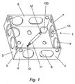
- An electrical mounting box 1 includes an open-ended box 2 made of conducting material.
- the open-ended box 2 is provided with a back wall 3 and four side walls 4, 5, 6 and 7.
- a plurality of push-out ovular holes 8 and push-out circular holes 9 are cut into the back wall 3 and side walls 4, 5, 6 and 7 of the box 2.
- the push-out ovular holes 8 and push-out circular holes 9 are designed to retain ovular and circular cables respectively.
- the open-ended box 2 is made from a sheet of an appropriate galvanized steel by progression route punching and the resulting flat shape is then folded into the desired box-shape.
- the open-ended box 2 is further provided with a plurality of screw-holding members 10 attached to at least two of its opposing sides walls (i.e. sidewalls 4 and 6 or 5 and 7).
- the screw-holding members 10 are attached to the side walls of the open-ended box 2 at positions proximal to its open end.
- the electrical mounting box 1 is further provided with an earth wire 11, a first end 12 of which has its insulation removed.
- the second end 13 of the earth wire 11 has its insulation cut but not removed, thereby facilitating the easy removal of the insulation whilst protecting the copper wire contained within.
- the first end 12 of the earth wire 11 is directly welded or otherwise fused to the back wall 3 of the open-ended box 2 so that the electrical mounting box 1 becomes a unitary structure of the earth wire 11 and the open-ended box 2.
- the earth wire 11 is thus an integral part of the resulting electrical mounting box 1.
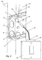
- the electrical mounting box 1 in use is placed in a chased groove 14 in a wall 15 in the same way as a conventional electrical mounting box. Electrical cables 16 are also hidden in a conduit in the chased groove 14 and threaded into the open-ended box 2 through the push-out ovular holes 8 or push-out circular holes 9 in its back wall 3 or side walls 4, 5, 6 or 7.
- the electrical mounting box 1 is plastered into place in the same way as a conventional electrical mounting box and the live and neutral wires of the power cables connected thereto.
- the screw-holding members 10 attached to the sidewalls of the open-ended box 2 enable the face-plate 19 of the switch or socket circuit 17 to be positioned in a variety of orientations relative to the electrical mounting box 1.
- the electrical mounting box 101 is further provided with at least one earth wire retaining member 20 attached to the interior of the open-ended box 102 in at least one corner position of the back wall 103.
- the first end 112 of the earth wire 111 is provided with an engaging member 21 connected to the copper wire contained within the earth wire 111.
- the engaging member 21 is connected to the first end 112 of the earth wire 111 is slidably inserted into the earth wire retaining member 20. A force is then applied to the engaging member 21 and earth wire retaining member 20 to cause permanent connection of the earth wire retaining member 20 to the engaging member 21.
- the installation process for the second embodiment of the invention proceeds in a similar manner to that of the first embodiment. It is envisaged that the electrical mounting box structure of the first and second embodiments could also be used for fitting earth wires to computer chassis and other electrical boxes, where the method of attachment of the earth wire to the equipment concerned would provide an improved electrical connection than conventional attachment methods.
Landscapes
- Engineering & Computer Science (AREA)
- Architecture (AREA)
- Civil Engineering (AREA)
- Structural Engineering (AREA)
- Connection Or Junction Boxes (AREA)
Applications Claiming Priority (2)
| Application Number | Priority Date | Filing Date | Title |
|---|---|---|---|
| IE20020847 | 2002-10-30 | ||
| IE20020847 | 2002-10-30 |
Publications (2)
| Publication Number | Publication Date |
|---|---|
| EP1416601A2 true EP1416601A2 (de) | 2004-05-06 |
| EP1416601A3 EP1416601A3 (de) | 2005-03-09 |
Family
ID=32088948
Family Applications (1)
| Application Number | Title | Priority Date | Filing Date |
|---|---|---|---|
| EP03394099A Withdrawn EP1416601A3 (de) | 2002-10-30 | 2003-10-30 | Elektrisches Befestigungsgehäuse |
Country Status (1)
| Country | Link |
|---|---|
| EP (1) | EP1416601A3 (de) |
Family Cites Families (6)
| Publication number | Priority date | Publication date | Assignee | Title |
|---|---|---|---|---|
| GB1126089A (en) * | 1966-11-05 | 1968-09-05 | H & L Appleby Ltd | Improvements in or relating to electric wall boxes |
| US3862351A (en) * | 1972-06-22 | 1975-01-21 | Nelco Corp | Molded electrical junction box |
| US3816638A (en) * | 1972-07-03 | 1974-06-11 | Appleton Electric Co | Electrical box ground screw mounting |
| CA1104242A (en) * | 1980-07-15 | 1981-06-30 | Biswa N. Bose | Electrical circuit incorporating electrical circuitry box having modified cover plate |
| GB2170361B (en) * | 1985-01-25 | 1989-06-14 | Appleby Limited H & L | Wall box |
| US6031907A (en) * | 1998-03-13 | 2000-02-29 | Lucent Technologies Inc. | Building entrance box with integrated flexible grounding |
-
2003
- 2003-10-30 EP EP03394099A patent/EP1416601A3/de not_active Withdrawn
Also Published As
| Publication number | Publication date |
|---|---|
| EP1416601A3 (de) | 2005-03-09 |
Similar Documents
| Publication | Publication Date | Title |
|---|---|---|
| US6786766B1 (en) | Electrical outlet box with secure quick connect and release features | |
| US7569771B2 (en) | Electrical receptacle and box apparatus | |
| CN100521421C (zh) | 快速组装电连接盒的设备以及方法 | |
| US10170878B1 (en) | Junction box with an integrated connection circuit | |
| CA2227659A1 (en) | Enclosure for interfacing electrical and control or communication devices | |
| CA2393014A1 (en) | Switch/power drop unit for modular wiring system | |
| US3900238A (en) | Addition of a stab ground wire to electrical receptacles, i.e. switches and plugs | |
| GB2404097A (en) | Wall Mounted Electrical Connector Module | |
| EP3104470B1 (de) | Steckdosenanordnung mit mehreren unterputzmontierbaren kästen | |
| US7888597B2 (en) | Fixture box enclosure | |
| EP1416601A2 (de) | Elektrisches Befestigungsgehäuse | |
| GB2430087A (en) | Mounting box for electrical wiring accessories with pluggable connector | |
| WO2018083435A1 (en) | Quicwire wiring system | |
| JP4534669B2 (ja) | 空気調和機の室内機 | |
| JP2009259419A (ja) | コネクター | |
| AU2018100721A4 (en) | Cable Junction | |
| JP2573456B2 (ja) | 屋内配線システム | |
| JP4443820B2 (ja) | 分電盤 | |
| KR200258011Y1 (ko) | 단자용 함체 | |
| JP3414716B2 (ja) | ケーブル接続具 | |
| KR20070120338A (ko) | 콘센트 구조 | |
| JPH0743955Y2 (ja) | 集中結線コネクタ | |
| KR20080004310U (ko) | 전기 통신용 노출박스 | |
| KR200392764Y1 (ko) | 전기공사용 콘크리트 매입형 단자박스 | |
| EP2662933A1 (de) | Leuchtenbuchsenausgang |
Legal Events
| Date | Code | Title | Description |
|---|---|---|---|
| PUAI | Public reference made under article 153(3) epc to a published international application that has entered the european phase |
Free format text: ORIGINAL CODE: 0009012 |
|
| AK | Designated contracting states |
Kind code of ref document: A2 Designated state(s): AT BE BG CH CY CZ DE DK EE ES FI FR GB GR HU IE IT LI LU MC NL PT RO SE SI SK TR |
|
| AX | Request for extension of the european patent |
Extension state: AL LT LV MK |
|
| PUAL | Search report despatched |
Free format text: ORIGINAL CODE: 0009013 |
|
| AK | Designated contracting states |
Kind code of ref document: A3 Designated state(s): AT BE BG CH CY CZ DE DK EE ES FI FR GB GR HU IE IT LI LU MC NL PT RO SE SI SK TR |
|
| AX | Request for extension of the european patent |
Extension state: AL LT LV MK |
|
| RIC1 | Information provided on ipc code assigned before grant |
Ipc: 7H 02G 3/08 B Ipc: 7H 02G 3/12 A |
|
| 17P | Request for examination filed |
Effective date: 20050909 |
|
| AKX | Designation fees paid |
Designated state(s): AT BE BG CH CY CZ DE DK EE ES FI FR GB GR HU IE IT LI LU MC NL PT RO SE SI SK TR |
|
| STAA | Information on the status of an ep patent application or granted ep patent |
Free format text: STATUS: THE APPLICATION IS DEEMED TO BE WITHDRAWN |
|
| 18D | Application deemed to be withdrawn |
Effective date: 20060613 |