EP1416603B1 - Schutz eines elektrischen Stromübertragungsnetzes - Google Patents
Schutz eines elektrischen Stromübertragungsnetzes Download PDFInfo
- Publication number
- EP1416603B1 EP1416603B1 EP02405935.4A EP02405935A EP1416603B1 EP 1416603 B1 EP1416603 B1 EP 1416603B1 EP 02405935 A EP02405935 A EP 02405935A EP 1416603 B1 EP1416603 B1 EP 1416603B1
- Authority
- EP
- European Patent Office
- Prior art keywords
- protection
- network
- central processing
- processing device
- function
- Prior art date
- Legal status (The legal status is an assumption and is not a legal conclusion. Google has not performed a legal analysis and makes no representation as to the accuracy of the status listed.)
- Expired - Lifetime
Links
Images

Classifications
-
- H—ELECTRICITY
- H02—GENERATION; CONVERSION OR DISTRIBUTION OF ELECTRIC POWER
- H02J—ELECTRIC POWER NETWORKS; CIRCUIT ARRANGEMENTS OR SYSTEMS FOR SUPPLYING OR DISTRIBUTING ELECTRIC POWER; SYSTEMS FOR STORING ELECTRIC ENERGY
- H02J3/00—Circuit arrangements for AC mains or AC distribution networks
-
- H—ELECTRICITY
- H02—GENERATION; CONVERSION OR DISTRIBUTION OF ELECTRIC POWER
- H02H—EMERGENCY PROTECTIVE CIRCUIT ARRANGEMENTS
- H02H7/00—Emergency protective circuit arrangements specially adapted for specific types of electric machines or apparatus or for sectionalised protection of cable or line systems, and effecting automatic switching in the event of an undesired change from normal working conditions
- H02H7/26—Sectionalised protection of cable or line systems, e.g. for disconnecting a section on which a short-circuit, earth fault, or arc discharge has occured
- H02H7/261—Sectionalised protection of cable or line systems, e.g. for disconnecting a section on which a short-circuit, earth fault, or arc discharge has occured involving signal transmission between at least two stations
- H02H7/263—Sectionalised protection of cable or line systems, e.g. for disconnecting a section on which a short-circuit, earth fault, or arc discharge has occured involving signal transmission between at least two stations involving transmissions of measured values
-
- H—ELECTRICITY
- H02—GENERATION; CONVERSION OR DISTRIBUTION OF ELECTRIC POWER
- H02H—EMERGENCY PROTECTIVE CIRCUIT ARRANGEMENTS
- H02H3/00—Emergency protective circuit arrangements for automatic disconnection directly responsive to an undesired change from normal electric working condition with or without subsequent reconnection ; integrated protection
- H02H3/02—Details
- H02H3/05—Details with means for increasing reliability, e.g. redundancy arrangements
-
- H—ELECTRICITY
- H02—GENERATION; CONVERSION OR DISTRIBUTION OF ELECTRIC POWER
- H02H—EMERGENCY PROTECTIVE CIRCUIT ARRANGEMENTS
- H02H3/00—Emergency protective circuit arrangements for automatic disconnection directly responsive to an undesired change from normal electric working condition with or without subsequent reconnection ; integrated protection
- H02H3/40—Emergency protective circuit arrangements for automatic disconnection directly responsive to an undesired change from normal electric working condition with or without subsequent reconnection ; integrated protection responsive to ratio of voltage and current
Definitions
- the invention relates to large-scale electric power transmission networks, and, more particularly, to a method, computer program and data processing system for the protection of an electric power transmission network as described in the preamble of claim 1, 9 and 10, respectively.
- Electric power transmission and distribution systems or networks comprise high-voltage tie lines for connecting geographically separated regions, and substations for transforming voltages and for switching connections between lines. Power generation and load flow in a network with several substations is controlled by a central energy management (EMS) system.
- EMS central energy management
- Protection of network components, in particular lines is achieved by control devices and methods, and in particular by protection devices that continuously measure e.g. currents, voltages, temperatures etc. locally and locally disconnect lines or other components when these measurements indicate an emergency, overload or fault condition.
- Such protection devices are e.g. overcurrent relays, differential protection devices, phase comparison relays or distance protection relays.
- the inventive method allows a cost-effective implementation of redundant protection functions. Furthermore, providing a redundant system with a different technology is better than e.g. simply duplicating existing equipment.
- the protection functions emulated in the central processing device are one of a differential protection function, a phase comparison function, an overcurrent detection function, a thermal overload detection function, or a distance protection function.
- values of predetermined parameters that are used in the protection function are adapted to measured values. This allows, on the one hand, incorporating updated estimates of network parameters, such as line impedances or equivalent model source voltages. These parameters are used, explicitly or implicitly, in the protection functions and are, according to the state of the art, assumed to be constant. On the other hand, this variant allows heuristically adapting limit values of conventional protection devices to changing network conditions, in particular to network stability.
- a distance protection function for a power line linking a first bus of the network to a second bus of the network is realized, and the method comprises at least one of the steps of
- the computer program for the control of an electric power transmission network is loadable into an internal memory of a digital computer, and comprises computer program code means to make, when said computer program code means is loaded in the computer, the computer execute the method according to the invention.
- a computer program product comprises a computer readable medium, having the computer program code means recorded thereon.
- a data processing system for the control of an electric power transmission network comprises means for carrying out the steps of the method according to the invention.
- the data processing system is an apparatus comprising a data processor, a memory coupled to the processor and computer program code means stored in said memory, where said computer program code means, when executed by the processor, causes the method according to the invention to be executed.
- Figure 1 schematically shows an information flow and function structure of a system providing redundant or backup protection according to the invention for a line located between a first bus A with a second bus B.
- a plurality of phasor measurement units 1,1',1",1"' is arranged to transmit synchronised phasor data to a central processing device 2.
- a first phasor measurement unit 1 measures a voltage phasor U A at the first bus A and a current phasor I A flowing from bus A into the line.
- a second phasor measurement unit 1' measures a voltage phasor U B and a current phasor I B at the second bus B.
- the central processing device 2 is arranged to transmit switching commands 6 to circuit breakers 4,4', either directly or through a substation control system controlling the circuit breakers 4,4'.
- the circuit breakers 4,4' are also, according to the state of the art, controlled by local protection devices 3,3'.
- the circuit breakers 4,4' disconnect an associated line or device if a switching command 6 is received from either a local protection device 3,3' or from the central processing device 2.
- the switching commands 6 from the central processing device 2 are transmitted to the local protection devices 3,3' or to a decision making device, by which other redundancy strategies are implemented. Such strategies are, for example:
- the redundant system is, with respect to software errors, more reliable than a redundant system made by simply duplicating conventional protection devices.
- Phasor data is determined with a phasor measurement unit residing, for example, at a feeder at the bay level of substations or at branching points along transmission lines.
- a voltage phasor represents, for example, a voltage of the feeder or line, while a current phasor represents current flowing through the feeder or line.
- the phasor data represents a phasor and may be a polar number, the absolute value of which corresponds to either the real magnitude or the RMS value of a quantity, and the phase argument to the phase angle at zero time.
- the phasor may be a complex number having real and imaginary parts or the phasor may use rectangular or exponential notation.
- conventional sensing devices used in power networks generally measure only scalar, average representations, such as the RMS value of a voltage, current etc.
- the phasor data is collected from phasor measurement units (PMUs) that are distributed over a large geographic area, i.e. over tens to hundreds of kilometres. Since the phasor data from these disparate sources are analysed in conjunction, they must refer to a common phase reference. Therefore, the different phasor measurement units must have local clocks that are synchronised to within a given precision. Such a synchronisation of the phasor measurement units is preferably achieved with a known time distribution system, for example the global positioning (GPS) system.
- GPS global positioning
- the phasor data 9 is determined at least every 200 or every 100 or preferably every 20 milliseconds, with a temporal resolution of preferably less than 1 millisecond.
- the temporal resolution is less than 10 microseconds, which corresponds to a phase error of 0.2 degrees.
- Each measurement is associated with a time stamp derived from the synchronised local clock.
- the phasor data therefore preferably comprises time stamp data.
- Figure 2 schematically shows an information flow and function structure of a system for adapting conventional protection devices according to the invention.
- the phasor measurement units 1,1',1",1''' again transmit phasor data to the central processing device 2.
- the central processing device 2 is configured to change 5 values of predetermined parameters that affect the protection functions implemented in the local protection devices 3,3'.
- the adaptation 5 of parameters is effected in a protection system that does not provide redundant protection functions but only adapts parameters of local protection devices 3,3'.
- adapted parameters are estimated network parameters, for example line impedances or equivalent model source voltages. These parameters are used, explicitly or implicitly, in the protection functions. According to the state of the art, they were assumed to be constant. Updating them according to phasor measurements such that they represent an actual state of the network increases the accuracy of the existing local protection functions and also of protection functions implemented in the central processing device 2.
- the parameters being adapted are limits or thresholds for monitored variables within local protection devices 3,3'.
- the local protection devices 3,3' are configured to trigger a protective action when such a monitored variable exceeds its limit.
- the protective action typically is the disconnecting of a line or a load.
- threshold values are determined from offline system studies. Therefore high reserve margins are necessary.
- the overload protection devices are adapted or temporarily blocked. Examples for such an adaptation of traditional local protection functions shall be given further on, in the context of overcurrent protection and distance protection.
- figure 1 and figure 2 may be implemented alternatively or simultaneously, using the same measurement, communications and computing hardware.
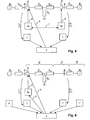
- the figures 3 through 5 show mainly the same elements as in figures 1 and 2 , but only those that are required for the specific situation of overcurrent protection, differential protection and distance protection, respectively.
- Figure 3 schematically shows an information flow and function structure for redundant overcurrent protection.
- the function of a local overcurrent protection device 3a is redundantly implemented by means of a first phasor measurement unit 1 and the central processing device 2.
- a first circuit breaker 4 is configured to accept commands 6 from both the overcurrent protection device 3a and from the central processing device 2.
- Continuous measurements I A , U A by the first phasor measurement unit 1 are processed by the central processing device 2 which, when an overcurrent is detected, sends a disconnecting command 6 to the first circuit breaker 4.
- the line to be protected lies between a first bus A and a second bus B. Network sections adjoining the line are reduced to equivalent circuits, e.g. Thévenin equivalent circuits.
- the first phasor measurement unit 1 alone is sufficient.
- the second and further phasor measurement units 1',1",1"' are optionally required for the adaptation 5 of protection function parameters.
- a current threshold in the overcurrent protection device 3a is modified 5 in accordance with measurements made by the entirety of phasor measurement units 1,1',1",1"'.
- the adaptation 5 of the current threshold in the overcurrent protection device 3a and/or the central processing device 2 takes estimates of the network state into account. Such estimates are represented by or computed from parameters of equivalent circuits represented by E 1 and Z 1e and E 2 and Z 2e . These parameters are, for example, computed from measurements made by the further phasor measurement units 1",1"' etc.
- the adaptation 5 involves a measure of the stability of the network.
- the central PMU system provides a voltage stability indicator I vs .
- I vs voltage stability indicator
- An example of such a stability indicator based on phasor measurements is described in EP-A-1 134 867 .
- Said application suggests shutting down loads when a stability margin gets too small.
- the disconnection of lines is temporarily inhibited, for the following reasons: When the network stability indicator indicates closeness to instability, this means the system is highly stressed and losing a device or line would probably lead to a collapse.
- a measure of oscillations is taken into account in the adaptation: With data from one or more of the time synchronized phasor measurement units 1,1',1",1"', an oscillation indicator values I o is computed. I o is computed e.g. by means of an integral criterion over a predetermined time.
- I o is computed e.g. by means of an integral criterion over a predetermined time.
- a simple variant of an oscillation indicator is implemented by integrating the absolute value of the difference between a current or voltage value and its average value over time.
- I max ⁇ I max 0 f ⁇ o ⁇ r I 0 ⁇ I 0 ⁇ set ⁇ f ⁇ o ⁇ r I 0 ⁇ I 0 ⁇ set
- thermal overload limits over- and undervoltage, over- and underfrequency.
- Figure 4 schematically shows an information flow and function structure for redundant differential protection.
- the function of a first differential protection device 3b and a second differential protection device 3b' is redundantly implemented by means of a first phasor measurement unit 1, a second phasor measurement unit 1' and the central processing device 2.
- circuit breakers 4,4' are controllable by the central processing device 2 and/or by associated differential protection devices 3b,3b'.
- the conventional differential protection devices 3b,3b' exchange current and/or phase information 7.
- the central processing device 2 processes current measurements by the phasor measurement units 1,1': If the difference between the currents flowing into and out of the line exceeds a certain threshold value, a fault current is detected. As a protective action, the central processing device 2 causes the line to be disconnected, preferably at both ends, by means of the circuit breakers 4,4'.
- the arrangement according to figure 4 may also be used to implement the function of a phase comparison relay:
- the phases of current and/or voltage at both sides of the line are measured with the phasor measurement units 1,1' and compared in the central processing device 2. If the phase difference exceeds a given threshold, then a fault is assumed to have occurred, and the line is disconnected, usually at both ends.
- one conventional phase comparison device may be omitted: At the sending end, at which power is delivered to the line, only a first phasor measurement unit 1 is installed, whereas the receiving end has an associated second phasor measurement unit 1' and a phase comparison device. The phase signals are compared in the central processing device 2 or transmitted to the phase comparison device located at the receiving end. Upon detection of a sufficiently large phase error, the circuit breakers 4,4' are opened.
- Figure 5 schematically shows an information flow and function structure for redundant distance protection:
- the function of a distance protection device 3c is redundantly implemented by means of a first phasor measurement unit 1, a second phasor measurement unit 1' and the central processing device 2.
- a first circuit breaker 4 is controllable by the central processing device 2 and/or by the associated distance protection device 3c.
- remote phasor measurement units represented in figure 5 by a third phasor measurement unit 1" and a fourth phasor measurement unit 1"', are used. More than two remote phasor measurement units 1",1"' may be used, although only two are shown in the figure.
- a distance protection relay measures an impedance observed in a certain direction, e.g. when "looking into” line AB in figure 5 from point A.
- the network equivalent in figure 5 represents the usual model for fault situations. It is shown here exemplarily for a phase to ground fault of a single line. Double lines or other faults are handled accordingly. If the observed impedance changes, there must be a fault with an impedance Rf.
- a distance protection relay is parameterized such that it covers ideally only the line where it is installed. To avoid an overreach into other lines, a security margin is set, which causes a the relay to cover only 50% to 80 % of the line. This means that a fault in the last 50% to 20 % of the line length is switched off later than theoretically necessary.
- zone 1 This basic functionality is called “zone 1" functionality.
- Other impedance settings are used to cover remote distances, as backups for the protection installed there.
- Zone 2 covers, for example, the next substation and a part of the next line.
- Zone 3 covers adjacent lines. Both zone 2 and zone 3 protection are configured to cause protective action slower than zone 1, resulting in a time-coordinated and staggered backup for the zone 1 protection in the overlapping zones.
- Zone 2 acts usually within about 0.4 second, and zone 3 within 1 to 2 seconds.
- the zones 1, 2 and 3 with respect to bus A are labelled as z1, z2 and z3, respectively.
- Zone 3 protection is not very reliable since, due to changing line parameters Z1i, Z2i and load situations, it is hard to configure.
- the main drawback is that only local information at the place where the relay is located is used. If the fault impedance Rf is neglected, the calculated impedance Z 1i,calc is e.g. equal to a difference of Phase Voltages at location A, divided by a difference of Phase Currents for a phase to phase fault. If the fault impedance Rf is not neglected, Z 1i,calc is Z 1i , + Rf (1 + I B /I A ). This signifies that remote information from point B is necessary to get accurate information for the location of the fault.
- the first one is to use local and remote information at the two points A and B from PMU measurements. This is proposed in Chen, et. al. "A new adaptive PMU based protection scheme for transposed/untransposed parallel transmission lines", IEEE Transactions on Power Delivery, Vol. 17, No. 2, April 2002 , shows an adaptive distance protection system.
- the distance D between bus A and the fault is a function of U A , U B , I A , I B , from which also the line parameters are calculated and adapted. From these measurements, which change drastically during the fault, trigger signals for fault detection are generated as well.
- the fault location and determination calculations are performed according to standard formulae derived from symmetrical component descriptions of the situation for particular faults, such as phase to ground or phase to phase, based on the network equivalent of the line between bus A and bus B as in figure 5 Well-known methods for this purpose are shown in Anderson, P.M. "Analysis of faulted power systems", ISBN 0-7803-1145-0, IEEE Press, 1995 .
- zone 2 and zone 3 protection can be implemented by applying the formula for the fault location and incorporating also the load current at point B.
- the second possibility is not to measure at point C but to determine a Thévenin equivalent for the remote area. This means determining Z 2e and E 2 from the measurements at point B before the fault according to a method as shown in e.g. EP-A-1 211 775 .
- the voltage at E 2 and the current from E 2 to B can be used to locate the fault in point B or between B and E2 with the common formula according to the standard procedure. With this approach, the zone 2 or zone 3 protection functionality can be implemented more accurate than with todays methods.
- a third alternative method is to determine the actual values for the line parameters according to figure 5 and the Thévenin equivalents at both ends continuously during fault-free operation, and to store this model in the local relay at point A, as shown e.g. in Xia, et al. "Adaptive Relay Setting for Stand-Alone Digital Distance Protection", IEEE Transactions on Power Delivery Vol. 9, No. 1, Jan. 1994 .
- the relay determines and locates the fault according to the updated model in figure 5 and from on-line measured local data relating to point A.
- the parameters E 1 , E 2 , Z 1e , Z 2e and the line parameters are continuously updated from measurements taken by the phasor measurement units 1,1',1",1"', i.e. including remote phasor measurement units 1",1"'.
- a general procedure for determining network parameters from distributed phasor measurements is described in EP application No. 01811253.2, filed 2001-12-21 .
- the protection scheme e.g. according to the Xia et al. paper cited above is then applied, but using the updated values of E 1 , E 2 , Z 1e , Z 2e .
- zone 3 protection is duplicated redundantly or replaced by a PMU-based system.
- zone 3 protection where a remote circuit breaker switches, only the faulted line is switched off and not larger part of the system.
- adaptation 5 of distance protection parameters is achieved as follows.
- Distance protection in particular zone 3 protection, is critical during system oscillations. Oscillations are therefore detected by configuring the central processing device 2 to determine an oscillation indicator I o .
- the conventional protection functions are partially or altogether omitted. and protection is realised by the central processing device 2 alone, based on the distributed phasor measurements.
- phasor values for currents and voltages valid for a specific point in the network are computed from phasor values measured at other locations. This is done by applying Kirchhoff's laws, as shown e.g. in European Patent Application No. 01811253.2, filed 2001-12-21 .
Landscapes
- Engineering & Computer Science (AREA)
- Power Engineering (AREA)
- Remote Monitoring And Control Of Power-Distribution Networks (AREA)
- Emergency Protection Circuit Devices (AREA)
Claims (13)
- Verfahren zum Schutz eines elektrischen Stromübertragungsnetzes, wobei lokale Schutzfunktionen durch mehrere lokale Schutzvorrichtungen (3, 3a, 3b, 3b', 3c) implementiert werden, die an mehreren Orten überall im Netz angeordnet sind,
dadurch gekennzeichnet, dass das Verfahren die folgenden Schritte aufweist:• Messen von Phasordaten für Spannungen und Ströme an mehreren Orten (A, B) des Netzes,• Senden der Phasordaten an eine zentrale Verarbeitungsvorrichtung (2),• Emulieren, in der zentralen Verarbeitungsvorrichtung (2), von Schutzfunktionen, welche in den lokalen Schutzvorrichtungen (3, 3a, 3b, 3b', 3c) implementiert sind, und• Ausführen, entsprechend einer gegebenen Redundanzstrategie, von Steuerbefehlen, welche von den lokalen Schutzvorrichtungen (3, 3a, 3b, 3b', 3c) und von der zentralen Verarbeitungsvorrichtung (2) redundant ausgegeben werden. - Verfahren nach Anspruch 1, wobei eine Schutzfunktion, die in der zentralen Verarbeitungsvorrichtung (2) emuliert wird, entweder eine Differentialschutzfunktion oder eine Phasenvergleichsfunktion oder eine Überstromdetektionsfunktion oder eine Detektionsfunktion für thermische Überlastung ist.
- Verfahren nach Anspruch 1, wobei eine Schutzfunktion, die in der zentralen Verarbeitungsvorrichtung (2) emuliert wird, eine Distanzschutzfunktion ist.
- Verfahren nach einem der Ansprüche 1 bis 3, welches den folgenden Schritt aufweist:• Anpassen von Werten vorbestimmter Parameter, welche in der Schutzfunktion verwendet werden, entsprechend gemessenen Phasorwerten.
- Verfahren nach Anspruch 4, wobei die vorbestimmten Parameter Impedanzen von Leitungen oder äquivalenten Schaltungen sind.
- Verfahren nach Anspruch 4, wobei die vorbestimmten Parameter Grenzwerte sind, welche, wenn sie überschritten werden, bewirken, dass eine Schutzmaßnahme ergriffen wird.
- Verfahren nach Anspruch 6, welches die folgenden Schritte aufweist:• Berechnen, aus gemessenen Phasorwerten, eines Stabilitätsmaßes des Netzes, und• Anpassen von Grenzwerten entsprechend dem Stabilitätsmaß.
- Verfahren nach Anspruch 4, mit Bezug auf Anspruch 3, wobei die Distanzschutzfunktion für eine Kraftstromleitung, die einen ersten Bus (A) des Netzes mit einem zweiten Bus (B) des Netzes verbindet, mindestens einen der folgenden Schritte aufweist:• Bestimmen einer äquivalenten Darstellung des Netzes, wie vom ersten Bus (A) aus gesehen, und• Bestimmen einer äquivalenten Darstellung des
Netzes, wie vom zweiten Bus (B) aus gesehen, sowie den folgenden Schritt:• Berechnen eines Distanzschutzalgorithmus, welcher wenigstens eine der äquivalenten Darstellungen des Netzes, wie vom ersten bzw. zweiten Bus aus gesehen, einbezieht. - Computerprogramm zum Schutz eines elektrischen Stromübertragungsnetzes, welches auf eine Datenverarbeitungseinheit ladbar und auf dieser ausführbar ist, wobei dieses Computerprogramm, wenn es ausgeführt wird, die Schritte nach einem der vorhergehenden Ansprüche ausführt.
- Datenverarbeitungssystem zum Schutz eines elektrischen Stromübertragungsnetzes, welches Mittel zum Ausführen der Schritte des Verfahrens nach einem der Ansprüche 1 bis 8 aufweist.
- Zentrale Verarbeitungsvorrichtung (2) zum Schutz eines elektrischen Stromübertragungsnetzes, welches mehrere lokale Schutzvorrichtungen (3, 3a, 3b, 3b', 3c) aufweist, wobei die Letzteren an einer ersten Vielzahl von Orten überall im Netz angeordnet sind und lokale Schutzfunktionen implementieren, wobei die zentrale Verarbeitungsvorrichtung dafür ausgelegt ist:• auf der Basis von Phasordaten für Spannungen und Ströme, die an einer zweiten Vielzahl von Orten (A, B) des Netzes gemessen und zu der zentralen Verarbeitungsvorrichtung übertragen werden, lokale Schutzfunktionen zu emulieren, welche in lokalen Schutzvorrichtungen implementiert sind, und• redundant Steuerbefehle auszugeben, um Befehle zu steuern, die von den lokalen Schutzvorrichtungen ausgegeben werden.
- Zentrale Verarbeitungsvorrichtung (2) nach Anspruch 11, wobei eine lokale Schutzfunktion, die in der zentralen Verarbeitungsvorrichtung (2) emuliert wird, entweder eine Differentialschutzfunktion oder eine Phasenvergleichsfunktion oder eine Überstromdetektionsfunktion oder eine Detektionsfunktion für thermische Überlastung oder eine Distanzschutzfunktion ist.
- Zentrale Verarbeitungsvorrichtung (2) nach Anspruch 11, welche ferner dafür ausgelegt ist,• Werte vorbestimmter Parameter, welche in der lokalen Schutzfunktion verwendet werden, entsprechend gemessenen Phasorwerten anzupassen.
Priority Applications (3)
| Application Number | Priority Date | Filing Date | Title |
|---|---|---|---|
| EP02405935.4A EP1416603B1 (de) | 2002-11-01 | 2002-11-01 | Schutz eines elektrischen Stromübertragungsnetzes |
| CA2446876A CA2446876C (en) | 2002-11-01 | 2003-10-27 | Protection of an electric power transmission network |
| US10/697,038 US6985800B2 (en) | 2002-11-01 | 2003-10-31 | Protection of an electric power transmission network |
Applications Claiming Priority (1)
| Application Number | Priority Date | Filing Date | Title |
|---|---|---|---|
| EP02405935.4A EP1416603B1 (de) | 2002-11-01 | 2002-11-01 | Schutz eines elektrischen Stromübertragungsnetzes |
Publications (2)
| Publication Number | Publication Date |
|---|---|
| EP1416603A1 EP1416603A1 (de) | 2004-05-06 |
| EP1416603B1 true EP1416603B1 (de) | 2015-01-21 |
Family
ID=32088113
Family Applications (1)
| Application Number | Title | Priority Date | Filing Date |
|---|---|---|---|
| EP02405935.4A Expired - Lifetime EP1416603B1 (de) | 2002-11-01 | 2002-11-01 | Schutz eines elektrischen Stromübertragungsnetzes |
Country Status (3)
| Country | Link |
|---|---|
| US (1) | US6985800B2 (de) |
| EP (1) | EP1416603B1 (de) |
| CA (1) | CA2446876C (de) |
Cited By (1)
| Publication number | Priority date | Publication date | Assignee | Title |
|---|---|---|---|---|
| EP4576465A1 (de) * | 2023-12-21 | 2025-06-25 | Analog Devices International Unlimited Company | Mehrheitswahlüberstromerkennungssystem |
Families Citing this family (32)
| Publication number | Priority date | Publication date | Assignee | Title |
|---|---|---|---|---|
| US7233843B2 (en) * | 2003-08-08 | 2007-06-19 | Electric Power Group, Llc | Real-time performance monitoring and management system |
| US7836506B2 (en) * | 2004-09-22 | 2010-11-16 | Cyberdefender Corporation | Threat protection network |
| US7408274B2 (en) * | 2004-12-30 | 2008-08-05 | Inpower Llc | Control and operating condition monitoring of dual series switch contactors for electric motor or other electrical load |
| US20070063664A1 (en) * | 2005-09-22 | 2007-03-22 | Avistar, Inc. | Phase identification apparatus having automatic gain control to prevent detector saturation |
| EP1780858A1 (de) * | 2005-10-31 | 2007-05-02 | ABB Technology AG | Anordnung und Verfahren zum Schutz eines elektrischen Stromversorgungssystems |
| EP1830447A1 (de) | 2006-03-02 | 2007-09-05 | ABB Research Ltd | Umrichtersteuereinheit mit Verwendung von Spannungs- und Stromvektoren mit Zeitstempel |
| US7693607B2 (en) * | 2006-09-07 | 2010-04-06 | General Electric Company | Protection and control system for electric power networks with signal and command interfaces at the primary equipment |
| US7489138B2 (en) | 2006-11-30 | 2009-02-10 | Honeywell International Inc. | Differential arc fault detection |
| US7499816B2 (en) * | 2006-12-12 | 2009-03-03 | Abb Research Ltd. | Estimation of real-time power system quantities using time-synchronized measurements |
| US7599161B2 (en) * | 2006-12-29 | 2009-10-06 | General Electric Company | Relay device and corresponding method |
| US7542256B2 (en) * | 2006-12-29 | 2009-06-02 | General Electric Company | Relay device and corresponding method |
| US7684900B2 (en) * | 2007-02-20 | 2010-03-23 | Abb Research Ltd. | Adaptive provision of protection function settings of electrical machines |
| EP2073342A1 (de) * | 2007-12-18 | 2009-06-24 | Siemens Aktiengesellschaft | Verfahren und Vorrichtung zur Ermittlung der elektrischen Wirkleistung von einem oder meheren Verbraucherabzweigen |
| EP2238664B1 (de) * | 2008-01-31 | 2017-03-22 | Siemens Aktiengesellschaft | Distanzschutzanordnung und verfahren zum überwachen einer elektrischen energieübertragungsleitung |
| EP2124311A1 (de) * | 2008-05-23 | 2009-11-25 | ABB Research LTD | Zeitverzögerungsausgleich einer Energieversorgungssystemsteuerung |
| JP5419485B2 (ja) * | 2009-02-09 | 2014-02-19 | 三菱電機株式会社 | 保護継電装置 |
| BRPI0924856B8 (pt) | 2009-06-11 | 2022-11-01 | Abb Research Ltd | Método para fornecer controle de um sistema de transmissão de energia e dispositivo de controle de energia |
| US20100332593A1 (en) * | 2009-06-29 | 2010-12-30 | Igor Barash | Systems and methods for operating an anti-malware network on a cloud computing platform |
| US8634965B1 (en) | 2010-12-03 | 2014-01-21 | Bei Gou | Computer-based method for power system state estimation |
| US9043040B2 (en) | 2012-01-31 | 2015-05-26 | General Electric Company | Power system stabilization |
| CN104025407A (zh) * | 2012-02-21 | 2014-09-03 | 株式会社东芝 | 综合单元以及保护继电器系统 |
| CN103296643B (zh) * | 2013-03-19 | 2017-02-22 | 昆明理工大学 | 一种基于广域信息电压相位差比较式孤岛检测及孤岛保护方法 |
| EP3173991A1 (de) | 2015-11-30 | 2017-05-31 | Siemens Aktiengesellschaft | Verfahren und vorrichtung zur automatischen erkennung von ähnlichkeiten zwischen störungen in einem netzwerk |
| US10027119B2 (en) | 2016-05-28 | 2018-07-17 | PXiSE Energy Solutions, LLC | Decoupling synchrophasor based control system for multiple distributed energy resources |
| US10615604B2 (en) | 2016-05-28 | 2020-04-07 | PXiSE Energy Solutions, LLC | Decoupling synchrophasor based control system for distributed energy resources |
| US10452032B1 (en) | 2016-09-08 | 2019-10-22 | PXiSE Energy Solutions, LLC | Optimizing power contribution of distributed energy resources for real time power demand scheduling |
| US10599175B1 (en) | 2017-02-28 | 2020-03-24 | PXiSE Energy Solutions, LLC | Time synchronized frequency and voltage regulation of electric power balancing areas |
| US11146066B2 (en) * | 2017-06-08 | 2021-10-12 | Power Management Holdings (U.S.), Inc. | Measurement-based dynamic modeling of an electrical network |
| US10990072B2 (en) | 2017-11-28 | 2021-04-27 | PXiSE Energy Solutions, LLC | Maintaining power grid stability using predicted data |
| CN110888401B (zh) * | 2018-09-11 | 2022-09-06 | 京东科技控股股份有限公司 | 火力发电机组燃烧控制优化方法、装置及可读存储介质 |
| CN110492449B (zh) * | 2019-07-16 | 2022-04-15 | 中国电力科学研究院有限公司 | 一种基于同塔多回线路的变时限距离保护计时方法及装置 |
| US11056912B1 (en) | 2021-01-25 | 2021-07-06 | PXiSE Energy Solutions, LLC | Power system optimization using hierarchical clusters |
Family Cites Families (6)
| Publication number | Priority date | Publication date | Assignee | Title |
|---|---|---|---|---|
| DE1134867B (de) * | 1960-12-09 | 1962-08-16 | Erich Ernst Pieper | Rollensatz zum Foerdern oder Abbremsen eines oder mehrerer parallel laufender Metallbaender |
| ES2320310T3 (es) | 2000-03-10 | 2009-05-21 | Abb Schweiz Ag | Metodo y dispositivo para evaluar la estabilidad de una red de transmision electrica. |
| US20040010350A1 (en) * | 2000-05-31 | 2004-01-15 | Per-Anders Lof | Distributed power generation system protection scheme |
| US6330141B1 (en) * | 2000-06-13 | 2001-12-11 | Eaton Corporation | Electronic protective relay with variable and fixed delay tally time of current protection |
| EP1211775B1 (de) | 2000-12-01 | 2004-07-14 | ABB Schweiz AG | Verfahren und Vorrichtung zur Stabilitätsauswertung eines Energieübertragungssystem |
| DE60108966D1 (de) | 2001-12-21 | 2005-03-24 | Abb Research Ltd | Zustandsbestimmung für ein Energieverteilungsnetz |
-
2002
- 2002-11-01 EP EP02405935.4A patent/EP1416603B1/de not_active Expired - Lifetime
-
2003
- 2003-10-27 CA CA2446876A patent/CA2446876C/en not_active Expired - Fee Related
- 2003-10-31 US US10/697,038 patent/US6985800B2/en not_active Expired - Lifetime
Cited By (1)
| Publication number | Priority date | Publication date | Assignee | Title |
|---|---|---|---|---|
| EP4576465A1 (de) * | 2023-12-21 | 2025-06-25 | Analog Devices International Unlimited Company | Mehrheitswahlüberstromerkennungssystem |
Also Published As
| Publication number | Publication date |
|---|---|
| US20040090725A1 (en) | 2004-05-13 |
| EP1416603A1 (de) | 2004-05-06 |
| US6985800B2 (en) | 2006-01-10 |
| CA2446876A1 (en) | 2004-05-01 |
| CA2446876C (en) | 2012-06-19 |
Similar Documents
| Publication | Publication Date | Title |
|---|---|---|
| EP1416603B1 (de) | Schutz eines elektrischen Stromübertragungsnetzes | |
| EP1949517B1 (de) | Fehlerschutzsystem und -verfahren für ein stromverteilungssystem | |
| US11258249B2 (en) | Primary and system protection for an electric power delivery system | |
| EP2111681B1 (de) | Ausfallschutz für ein sicherungsbewahrendes stromverteilungssystem | |
| US10236675B2 (en) | Fault detection and protection during steady state using traveling waves | |
| US10756571B2 (en) | System and method for stabilizing power system | |
| CA3068231C (en) | Communication-based permissive protection scheme for power distribution networks | |
| Calero | Mutual impedance in parallel lines–protective relaying and fault location considerations | |
| EP3291399B1 (de) | Schutzvorrichtung | |
| US20210249853A1 (en) | Electrical protection system and a method thereof | |
| CN107727986B (zh) | 一种具有后备功能的小电流接地故障选线系统及方法 | |
| EP2779342B1 (de) | Schutzsteuersystem, schutzsteuervorrichtung und zusammenführungseinheit | |
| US11114892B2 (en) | Electric power system transducer failure monitor and measurement recovery | |
| WO2025259815A1 (en) | Power outage restoration in distribution systems assisted by state estimation | |
| EP3460935B1 (de) | Verfahren und system für speiserschutz in einem elektrischen netzwerk | |
| JP5450149B2 (ja) | 配電線地絡保護継電システム | |
| CN110932244A (zh) | 变电站全站保护出口压板均未投的继电保护方法 | |
| Allen | Effects of wide-area control on the protection and operation of distribution networks | |
| KR102127471B1 (ko) | 변전소 종합 ai 후비보호시스템 | |
| CN121566450A (zh) | 适用于多能场景下馈线自动化的故障信息生成方法和系统 | |
| GB2342518A (en) | Overcurrent protection for distribution networks | |
| JPH0520976B2 (de) |
Legal Events
| Date | Code | Title | Description |
|---|---|---|---|
| PUAI | Public reference made under article 153(3) epc to a published international application that has entered the european phase |
Free format text: ORIGINAL CODE: 0009012 |
|
| AK | Designated contracting states |
Kind code of ref document: A1 Designated state(s): AT BE BG CH CY CZ DE DK EE ES FI FR GB GR IE IT LI LU MC NL PT SE SK TR |
|
| AX | Request for extension of the european patent |
Extension state: AL LT LV MK RO SI |
|
| 17P | Request for examination filed |
Effective date: 20041021 |
|
| AKX | Designation fees paid |
Designated state(s): AT BE BG CH CY CZ DE DK EE ES FI FR GB GR IE IT LI LU MC NL PT SE SK TR |
|
| GRAP | Despatch of communication of intention to grant a patent |
Free format text: ORIGINAL CODE: EPIDOSNIGR1 |
|
| INTG | Intention to grant announced |
Effective date: 20141017 |
|
| GRAS | Grant fee paid |
Free format text: ORIGINAL CODE: EPIDOSNIGR3 |
|
| GRAA | (expected) grant |
Free format text: ORIGINAL CODE: 0009210 |
|
| AK | Designated contracting states |
Kind code of ref document: B1 Designated state(s): AT BE BG CH CY CZ DE DK EE ES FI FR GB GR IE IT LI LU MC NL PT SE SK TR |
|
| REG | Reference to a national code |
Ref country code: GB Ref legal event code: FG4D |
|
| REG | Reference to a national code |
Ref country code: CH Ref legal event code: EP |
|
| REG | Reference to a national code |
Ref country code: IE Ref legal event code: FG4D |
|
| REG | Reference to a national code |
Ref country code: AT Ref legal event code: REF Ref document number: 707777 Country of ref document: AT Kind code of ref document: T Effective date: 20150215 |
|
| REG | Reference to a national code |
Ref country code: DE Ref legal event code: R096 Ref document number: 60246923 Country of ref document: DE Effective date: 20150305 |
|
| REG | Reference to a national code |
Ref country code: SE Ref legal event code: TRGR |
|
| REG | Reference to a national code |
Ref country code: NL Ref legal event code: VDEP Effective date: 20150121 |
|
| REG | Reference to a national code |
Ref country code: AT Ref legal event code: MK05 Ref document number: 707777 Country of ref document: AT Kind code of ref document: T Effective date: 20150121 |
|
| PG25 | Lapsed in a contracting state [announced via postgrant information from national office to epo] |
Ref country code: FI Free format text: LAPSE BECAUSE OF FAILURE TO SUBMIT A TRANSLATION OF THE DESCRIPTION OR TO PAY THE FEE WITHIN THE PRESCRIBED TIME-LIMIT Effective date: 20150121 Ref country code: ES Free format text: LAPSE BECAUSE OF FAILURE TO SUBMIT A TRANSLATION OF THE DESCRIPTION OR TO PAY THE FEE WITHIN THE PRESCRIBED TIME-LIMIT Effective date: 20150121 Ref country code: BG Free format text: LAPSE BECAUSE OF FAILURE TO SUBMIT A TRANSLATION OF THE DESCRIPTION OR TO PAY THE FEE WITHIN THE PRESCRIBED TIME-LIMIT Effective date: 20150421 |
|
| PG25 | Lapsed in a contracting state [announced via postgrant information from national office to epo] |
Ref country code: NL Free format text: LAPSE BECAUSE OF FAILURE TO SUBMIT A TRANSLATION OF THE DESCRIPTION OR TO PAY THE FEE WITHIN THE PRESCRIBED TIME-LIMIT Effective date: 20150121 Ref country code: GR Free format text: LAPSE BECAUSE OF FAILURE TO SUBMIT A TRANSLATION OF THE DESCRIPTION OR TO PAY THE FEE WITHIN THE PRESCRIBED TIME-LIMIT Effective date: 20150422 Ref country code: AT Free format text: LAPSE BECAUSE OF FAILURE TO SUBMIT A TRANSLATION OF THE DESCRIPTION OR TO PAY THE FEE WITHIN THE PRESCRIBED TIME-LIMIT Effective date: 20150121 |
|
| REG | Reference to a national code |
Ref country code: DE Ref legal event code: R097 Ref document number: 60246923 Country of ref document: DE |
|
| PG25 | Lapsed in a contracting state [announced via postgrant information from national office to epo] |
Ref country code: CZ Free format text: LAPSE BECAUSE OF FAILURE TO SUBMIT A TRANSLATION OF THE DESCRIPTION OR TO PAY THE FEE WITHIN THE PRESCRIBED TIME-LIMIT Effective date: 20150121 Ref country code: DK Free format text: LAPSE BECAUSE OF FAILURE TO SUBMIT A TRANSLATION OF THE DESCRIPTION OR TO PAY THE FEE WITHIN THE PRESCRIBED TIME-LIMIT Effective date: 20150121 Ref country code: EE Free format text: LAPSE BECAUSE OF FAILURE TO SUBMIT A TRANSLATION OF THE DESCRIPTION OR TO PAY THE FEE WITHIN THE PRESCRIBED TIME-LIMIT Effective date: 20150121 Ref country code: SK Free format text: LAPSE BECAUSE OF FAILURE TO SUBMIT A TRANSLATION OF THE DESCRIPTION OR TO PAY THE FEE WITHIN THE PRESCRIBED TIME-LIMIT Effective date: 20150121 |
|
| REG | Reference to a national code |
Ref country code: FR Ref legal event code: PLFP Year of fee payment: 14 |
|
| PLBE | No opposition filed within time limit |
Free format text: ORIGINAL CODE: 0009261 |
|
| STAA | Information on the status of an ep patent application or granted ep patent |
Free format text: STATUS: NO OPPOSITION FILED WITHIN TIME LIMIT |
|
| 26N | No opposition filed |
Effective date: 20151022 |
|
| PG25 | Lapsed in a contracting state [announced via postgrant information from national office to epo] |
Ref country code: IT Free format text: LAPSE BECAUSE OF FAILURE TO SUBMIT A TRANSLATION OF THE DESCRIPTION OR TO PAY THE FEE WITHIN THE PRESCRIBED TIME-LIMIT Effective date: 20150121 |
|
| PGFP | Annual fee paid to national office [announced via postgrant information from national office to epo] |
Ref country code: GB Payment date: 20151118 Year of fee payment: 14 |
|
| PGFP | Annual fee paid to national office [announced via postgrant information from national office to epo] |
Ref country code: SE Payment date: 20151118 Year of fee payment: 14 |
|
| PG25 | Lapsed in a contracting state [announced via postgrant information from national office to epo] |
Ref country code: BE Free format text: LAPSE BECAUSE OF FAILURE TO SUBMIT A TRANSLATION OF THE DESCRIPTION OR TO PAY THE FEE WITHIN THE PRESCRIBED TIME-LIMIT Effective date: 20150121 |
|
| PG25 | Lapsed in a contracting state [announced via postgrant information from national office to epo] |
Ref country code: MC Free format text: LAPSE BECAUSE OF FAILURE TO SUBMIT A TRANSLATION OF THE DESCRIPTION OR TO PAY THE FEE WITHIN THE PRESCRIBED TIME-LIMIT Effective date: 20150121 Ref country code: LU Free format text: LAPSE BECAUSE OF FAILURE TO SUBMIT A TRANSLATION OF THE DESCRIPTION OR TO PAY THE FEE WITHIN THE PRESCRIBED TIME-LIMIT Effective date: 20151101 |
|
| REG | Reference to a national code |
Ref country code: CH Ref legal event code: PL |
|
| PG25 | Lapsed in a contracting state [announced via postgrant information from national office to epo] |
Ref country code: LI Free format text: LAPSE BECAUSE OF NON-PAYMENT OF DUE FEES Effective date: 20151130 Ref country code: CH Free format text: LAPSE BECAUSE OF NON-PAYMENT OF DUE FEES Effective date: 20151130 |
|
| REG | Reference to a national code |
Ref country code: IE Ref legal event code: MM4A |
|
| PG25 | Lapsed in a contracting state [announced via postgrant information from national office to epo] |
Ref country code: IE Free format text: LAPSE BECAUSE OF NON-PAYMENT OF DUE FEES Effective date: 20151101 |
|
| REG | Reference to a national code |
Ref country code: FR Ref legal event code: PLFP Year of fee payment: 15 |
|
| PG25 | Lapsed in a contracting state [announced via postgrant information from national office to epo] |
Ref country code: CY Free format text: LAPSE BECAUSE OF FAILURE TO SUBMIT A TRANSLATION OF THE DESCRIPTION OR TO PAY THE FEE WITHIN THE PRESCRIBED TIME-LIMIT Effective date: 20150121 |
|
| REG | Reference to a national code |
Ref country code: SE Ref legal event code: EUG |
|
| GBPC | Gb: european patent ceased through non-payment of renewal fee |
Effective date: 20161101 |
|
| PG25 | Lapsed in a contracting state [announced via postgrant information from national office to epo] |
Ref country code: TR Free format text: LAPSE BECAUSE OF FAILURE TO SUBMIT A TRANSLATION OF THE DESCRIPTION OR TO PAY THE FEE WITHIN THE PRESCRIBED TIME-LIMIT Effective date: 20150121 Ref country code: SE Free format text: LAPSE BECAUSE OF NON-PAYMENT OF DUE FEES Effective date: 20161102 |
|
| REG | Reference to a national code |
Ref country code: FR Ref legal event code: PLFP Year of fee payment: 16 |
|
| PG25 | Lapsed in a contracting state [announced via postgrant information from national office to epo] |
Ref country code: GB Free format text: LAPSE BECAUSE OF NON-PAYMENT OF DUE FEES Effective date: 20161101 |
|
| PG25 | Lapsed in a contracting state [announced via postgrant information from national office to epo] |
Ref country code: PT Free format text: LAPSE BECAUSE OF FAILURE TO SUBMIT A TRANSLATION OF THE DESCRIPTION OR TO PAY THE FEE WITHIN THE PRESCRIBED TIME-LIMIT Effective date: 20150121 |
|
| REG | Reference to a national code |
Ref country code: DE Ref legal event code: R081 Ref document number: 60246923 Country of ref document: DE Owner name: HITACHI ENERGY SWITZERLAND AG, CH Free format text: FORMER OWNER: ABB RESEARCH LTD., ZUERICH, CH Ref country code: DE Ref legal event code: R082 Ref document number: 60246923 Country of ref document: DE Representative=s name: ZIMMERMANN & PARTNER PATENTANWAELTE MBB, DE Ref country code: DE Ref legal event code: R081 Ref document number: 60246923 Country of ref document: DE Owner name: ABB SCHWEIZ AG, CH Free format text: FORMER OWNER: ABB RESEARCH LTD., ZUERICH, CH Ref country code: DE Ref legal event code: R081 Ref document number: 60246923 Country of ref document: DE Owner name: ABB POWER GRIDS SWITZERLAND AG, CH Free format text: FORMER OWNER: ABB RESEARCH LTD., ZUERICH, CH Ref country code: DE Ref legal event code: R082 Ref document number: 60246923 Country of ref document: DE Representative=s name: DENNEMEYER & ASSOCIATES S.A., DE |
|
| REG | Reference to a national code |
Ref country code: DE Ref legal event code: R081 Ref document number: 60246923 Country of ref document: DE Owner name: HITACHI ENERGY SWITZERLAND AG, CH Free format text: FORMER OWNER: ABB SCHWEIZ AG, BADEN, CH Ref country code: DE Ref legal event code: R082 Ref document number: 60246923 Country of ref document: DE Representative=s name: DENNEMEYER & ASSOCIATES S.A., DE Ref country code: DE Ref legal event code: R081 Ref document number: 60246923 Country of ref document: DE Owner name: ABB POWER GRIDS SWITZERLAND AG, CH Free format text: FORMER OWNER: ABB SCHWEIZ AG, BADEN, CH |
|
| PGFP | Annual fee paid to national office [announced via postgrant information from national office to epo] |
Ref country code: DE Payment date: 20211118 Year of fee payment: 20 Ref country code: FR Payment date: 20211119 Year of fee payment: 20 |
|
| REG | Reference to a national code |
Ref country code: DE Ref legal event code: R081 Ref document number: 60246923 Country of ref document: DE Owner name: HITACHI ENERGY SWITZERLAND AG, CH Free format text: FORMER OWNER: ABB POWER GRIDS SWITZERLAND AG, BADEN, CH |
|
| REG | Reference to a national code |
Ref country code: DE Ref legal event code: R071 Ref document number: 60246923 Country of ref document: DE |