EP1417110B1 - Fördereinheit zur anordnung in einem schwalltopf eines kraftstoffbehälters eines kraftfahrzeuges - Google Patents
Fördereinheit zur anordnung in einem schwalltopf eines kraftstoffbehälters eines kraftfahrzeuges Download PDFInfo
- Publication number
- EP1417110B1 EP1417110B1 EP02758091A EP02758091A EP1417110B1 EP 1417110 B1 EP1417110 B1 EP 1417110B1 EP 02758091 A EP02758091 A EP 02758091A EP 02758091 A EP02758091 A EP 02758091A EP 1417110 B1 EP1417110 B1 EP 1417110B1
- Authority
- EP
- European Patent Office
- Prior art keywords
- pump
- fuel
- housing part
- filter element
- unit according
- Prior art date
- Legal status (The legal status is an assumption and is not a legal conclusion. Google has not performed a legal analysis and makes no representation as to the accuracy of the status listed.)
- Expired - Lifetime
Links
- 239000002828 fuel tank Substances 0.000 title claims description 13
- 239000000446 fuel Substances 0.000 claims description 51
- 238000002485 combustion reaction Methods 0.000 claims description 4
- 238000001914 filtration Methods 0.000 claims description 3
- 239000012530 fluid Substances 0.000 claims 2
- 238000005086 pumping Methods 0.000 claims 2
- 238000004519 manufacturing process Methods 0.000 description 3
- 239000004744 fabric Substances 0.000 description 2
- 239000003380 propellant Substances 0.000 description 2
- 239000004604 Blowing Agent Substances 0.000 description 1
- 101100298225 Caenorhabditis elegans pot-2 gene Proteins 0.000 description 1
- 238000010276 construction Methods 0.000 description 1
- 238000003780 insertion Methods 0.000 description 1
- 230000037431 insertion Effects 0.000 description 1
- 239000000463 material Substances 0.000 description 1
- 239000002184 metal Substances 0.000 description 1
Images
Classifications
-
- F—MECHANICAL ENGINEERING; LIGHTING; HEATING; WEAPONS; BLASTING
- F02—COMBUSTION ENGINES; HOT-GAS OR COMBUSTION-PRODUCT ENGINE PLANTS
- F02M—SUPPLYING COMBUSTION ENGINES IN GENERAL WITH COMBUSTIBLE MIXTURES OR CONSTITUENTS THEREOF
- F02M37/00—Apparatus or systems for feeding liquid fuel from storage containers to carburettors or fuel-injection apparatus; Arrangements for purifying liquid fuel specially adapted for, or arranged on, internal-combustion engines
- F02M37/02—Feeding by means of suction apparatus, e.g. by air flow through carburettors
- F02M37/025—Feeding by means of a liquid fuel-driven jet pump
-
- B—PERFORMING OPERATIONS; TRANSPORTING
- B60—VEHICLES IN GENERAL
- B60K—ARRANGEMENT OR MOUNTING OF PROPULSION UNITS OR OF TRANSMISSIONS IN VEHICLES; ARRANGEMENT OR MOUNTING OF PLURAL DIVERSE PRIME-MOVERS IN VEHICLES; AUXILIARY DRIVES FOR VEHICLES; INSTRUMENTATION OR DASHBOARDS FOR VEHICLES; ARRANGEMENTS IN CONNECTION WITH COOLING, AIR INTAKE, GAS EXHAUST OR FUEL SUPPLY OF PROPULSION UNITS IN VEHICLES
- B60K15/00—Arrangement in connection with fuel supply of combustion engines or other fuel consuming energy converters, e.g. fuel cells; Mounting or construction of fuel tanks
- B60K15/03—Fuel tanks
- B60K15/077—Fuel tanks with means modifying or controlling distribution or motion of fuel, e.g. to prevent noise, surge, splash or fuel starvation
-
- F—MECHANICAL ENGINEERING; LIGHTING; HEATING; WEAPONS; BLASTING
- F02—COMBUSTION ENGINES; HOT-GAS OR COMBUSTION-PRODUCT ENGINE PLANTS
- F02M—SUPPLYING COMBUSTION ENGINES IN GENERAL WITH COMBUSTIBLE MIXTURES OR CONSTITUENTS THEREOF
- F02M37/00—Apparatus or systems for feeding liquid fuel from storage containers to carburettors or fuel-injection apparatus; Arrangements for purifying liquid fuel specially adapted for, or arranged on, internal-combustion engines
- F02M37/04—Feeding by means of driven pumps
- F02M37/08—Feeding by means of driven pumps electrically driven
- F02M37/10—Feeding by means of driven pumps electrically driven submerged in fuel, e.g. in reservoir
- F02M37/106—Feeding by means of driven pumps electrically driven submerged in fuel, e.g. in reservoir the pump being installed in a sub-tank
-
- B—PERFORMING OPERATIONS; TRANSPORTING
- B60—VEHICLES IN GENERAL
- B60K—ARRANGEMENT OR MOUNTING OF PROPULSION UNITS OR OF TRANSMISSIONS IN VEHICLES; ARRANGEMENT OR MOUNTING OF PLURAL DIVERSE PRIME-MOVERS IN VEHICLES; AUXILIARY DRIVES FOR VEHICLES; INSTRUMENTATION OR DASHBOARDS FOR VEHICLES; ARRANGEMENTS IN CONNECTION WITH COOLING, AIR INTAKE, GAS EXHAUST OR FUEL SUPPLY OF PROPULSION UNITS IN VEHICLES
- B60K15/00—Arrangement in connection with fuel supply of combustion engines or other fuel consuming energy converters, e.g. fuel cells; Mounting or construction of fuel tanks
- B60K15/03—Fuel tanks
- B60K2015/03105—Fuel tanks with supplementary interior tanks inside the fuel tank
-
- B—PERFORMING OPERATIONS; TRANSPORTING
- B60—VEHICLES IN GENERAL
- B60K—ARRANGEMENT OR MOUNTING OF PROPULSION UNITS OR OF TRANSMISSIONS IN VEHICLES; ARRANGEMENT OR MOUNTING OF PLURAL DIVERSE PRIME-MOVERS IN VEHICLES; AUXILIARY DRIVES FOR VEHICLES; INSTRUMENTATION OR DASHBOARDS FOR VEHICLES; ARRANGEMENTS IN CONNECTION WITH COOLING, AIR INTAKE, GAS EXHAUST OR FUEL SUPPLY OF PROPULSION UNITS IN VEHICLES
- B60K15/00—Arrangement in connection with fuel supply of combustion engines or other fuel consuming energy converters, e.g. fuel cells; Mounting or construction of fuel tanks
- B60K15/03—Fuel tanks
- B60K2015/03111—Swirl pots
-
- B—PERFORMING OPERATIONS; TRANSPORTING
- B60—VEHICLES IN GENERAL
- B60K—ARRANGEMENT OR MOUNTING OF PROPULSION UNITS OR OF TRANSMISSIONS IN VEHICLES; ARRANGEMENT OR MOUNTING OF PLURAL DIVERSE PRIME-MOVERS IN VEHICLES; AUXILIARY DRIVES FOR VEHICLES; INSTRUMENTATION OR DASHBOARDS FOR VEHICLES; ARRANGEMENTS IN CONNECTION WITH COOLING, AIR INTAKE, GAS EXHAUST OR FUEL SUPPLY OF PROPULSION UNITS IN VEHICLES
- B60K15/00—Arrangement in connection with fuel supply of combustion engines or other fuel consuming energy converters, e.g. fuel cells; Mounting or construction of fuel tanks
- B60K15/03—Fuel tanks
- B60K2015/03236—Fuel tanks characterised by special filters, the mounting thereof
Definitions
- the invention relates to a delivery unit for arrangement in a surge pot of a fuel tank of a motor vehicle with a pump provided for the promotion of fuel to an internal combustion engine of the motor vehicle fuel pump connected to the fuel pump suction pump for conveying fuel from the fuel tank into the surge tank and with at least one filter element for filtering fuel, wherein a housing part connected to the fuel pump has two channels provided for guiding the fuel.
- a conveyor unit according to the preamble of claim 9.
- Such conveyor units are known from US-A-4,860,714.
- Such conveyor units are widely used in today's motor vehicles and are known in practice.
- the housing part of the known conveyor unit has a flange, with which it is inserted into a recess of the baffle and sealed against this.
- the leading to the suction side of the suction jet pump channel is guided to the flange.
- the filter element is at the bottom attached to the swirl pot and has an edge with which it is sealed against the swirl pot.
- the invention is based on the problem to design a delivery unit of the type mentioned so that it is particularly simple and allows extensive pre-assembly.
- the housing part is designed for holding the at least one filter element and the channel is guided exclusively within the housing part of the suction jet pump and / or by the fuel pump to the filter element.
- the delivery unit according to the invention can be pre-assembled outside the fuel tank and the swirl pot with the filter element and the housing part and then mounted as a preassembled unit in the swirl pot. Since the channel leading to the filter element is arranged exclusively within the housing part, multiple seals between the housing part and the filter element are avoided. As a result, the conveyor unit according to the invention requires a particularly small number of components.
- the conveyor unit according to the invention is therefore particularly simple in construction and can be manufactured particularly cost-effectively.
- Suction jet pump is made in one piece with the housing part.
- the suction jet pump could for example be connected via a hose to the fuel pump.
- the housing part has a channel for a propellant conduit of the suction jet pump.
- a separate production of the suction jet pump and the housing part is usually required when the delivery unit is provided for different baffles and fuel tank.
- the pre-assembly of the conveyor unit according to the invention is particularly simple when the housing part includes the suction jet pump, or has a receptacle for the suction jet pump or a portion of the suction jet pump.
- connection of the housing part with the fuel pump according to another advantageous embodiment of the invention has a high stability, when the housing part has an annular, biased against the fuel pump flange. Furthermore, the housing part thereby requires a particularly low material usage.
- the housing part could be rolled, for example, with a housing part made of sheet metal of the fuel pump.
- the assembly and disassembly of the housing part designed according to another advantageous embodiment of the invention is particularly simple if the housing part has a plug connection to the fuel pump.
- the problem underlying the invention is also solved according to claim 9, characterized in that a channel of the blowing agent line of the suction jet pump has a through the inlet portion having a housing part up to the fuel pump passed through pipe section.
- the conveyor unit according to the invention is particularly compact. Furthermore, inlet areas with very large dimensions are avoided, which were previously necessary to avoid flow losses.
- the conveying unit according to the invention requires particularly few components to be mounted when the filter element is manufactured in one piece with the housing part.
- the filter element can be formed, for example, as a perforation of a wall of the housing part.
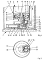
- the delivery unit 2 which comprises a fuel pump 5 driven by an electric motor 4, is arranged in a surge pot 3.
- the fuel pump 5 has an arranged between two stationary housing parts 6, 7, drivable by the electric motor 4 impeller 8.
- two rings of vane chambers 9 - 11 are arranged.
- the housing parts 6, 7 each have partially annular channels 15-17 extending from an inlet region 12 to an outlet region 13, 14. the partially annular channels 15 - 17 form with the blade chambers 9 - 11 delivery chambers 18, 19 for conveying the fuel.
- the fuel pump 5 is thus designed as a side channel pump.
- fuel is sucked out of the swirl pot 3 via a filter element 20.
- the radially outer delivery chamber 18 of the fuel is passed through the conveyor unit 2 to an internal combustion engine, not shown, of the motor vehicle.
- the radially inner delivery chamber 19 is used to deliver fuel as a propellant to a suction jet pump 21.
- the suction jet pump 21 sucks fuel through an opening in the bottom of the surge pot 3 and promotes this in the surge chamber.
- the suction jet pump 21 and to the filter element 20 and the fuel pump 5 leading fittings 22, 23 are as common housing part 24 made. Furthermore, the common housing part 24 has one of the radial inner delivery chamber 19 to a nozzle 25 of the suction jet pump 21 guided pipe section 26 with channel 27. The housing part 24 also has a channel 30 which is guided up to an inlet region 29 of the suction jet pump 21 arranged between the nozzle 25 and a mixing tube 28. The channel 30 is guided through the bottom of the swirl pot 2. At the fuel tank 1 facing the end of the channel 30, a filter element 31 is arranged. This filter element 31 is manufactured in one piece with the housing part 24.
- the connecting piece 22 of the housing part 24 is sealed by means of an O-ring 32 with respect to the lower housing part 7 of the fuel pump 5 and can be plugged into this. Furthermore, the housing part 24 has a channel 33 which is guided by the filter element 20 arranged in the surge pot 3 up to the inlet region 12 of the delivery chambers 18, 19. Above the inlet region 29 of the suction jet pump 21 there is a collecting space 34 for fuel to be sucked.
- FIG. 2 shows that the connecting piece 22 has a dividing wall 35 for separating the channel 33 of the inlet region 12 of the delivery chambers from the collecting space 34.
- the pipe section 26 guided to the nozzle 25 of the suction jet pump 21 shown in FIG. 1 is guided through the collecting space 34.
- the radially inner part-annular channel 17 can extend over a particularly large angular range.
- the radially outer part-annular channel 16 ends shortly before the inlet region 12 of the fuel pump fifth
- FIG 3 shows the channels 27, 30, 33 having housing part 24 of Figure 1 in a sectional view taken along the line III - III. It can be seen here that the filter element 20 arranged within the swirl pot 3 has a connection piece 36 inserted into the channel 33 of the housing part 24 and a connection piece 36 attached to the connection piece 36 Filter fabric 37 has.
- the housing part 24 can thus be pre-assembled with the filter element 20 to a structural unit and then connect to the fuel pump 5 of Figure 1.
- the projecting into the fuel tank filter element 31 has a one-piece manufactured with the housing part 24 filter fabric 38 and thus forms with the housing part 24 a structural unit.
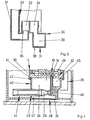
- FIG. 4 shows a delivery unit 39 in which a housing part 40 fastened to the fuel pump 5 has a flange 41. This flange 41 is engaged behind by a flanged plate edge 42 of the fuel pump 5. Furthermore, the housing part 40 has a receptacle 43 for insertion of an integrally manufactured suction jet pump 44. As an alternative to the one-piece production of the suction jet pump, the housing part 40 may also have a receptacle, not shown, for a portion of the suction jet pump.
- the housing part 40 has a channel 45 for connecting the inlet region 12 of the fuel pump 5 with the filter element 20 arranged inside the surge pot, a channel 46 for connecting the suction jet pump 44 to the outlet region 14 of the radially inner delivery chamber 19 and a channel 47 for connecting the inlet region 29
- the housing part 40 has a collecting space 34 for the fuel to be sucked by the suction jet pump 44 and a pipe section 49 for receiving the channel 46. Otherwise, the housing part 40 as the housing part 24 of the conveyor unit 2 of FIG 1 be formed.
Landscapes
- Engineering & Computer Science (AREA)
- Chemical & Material Sciences (AREA)
- Combustion & Propulsion (AREA)
- Mechanical Engineering (AREA)
- General Engineering & Computer Science (AREA)
- Life Sciences & Earth Sciences (AREA)
- Sustainable Development (AREA)
- Sustainable Energy (AREA)
- Transportation (AREA)
- Cooling, Air Intake And Gas Exhaust, And Fuel Tank Arrangements In Propulsion Units (AREA)
- Jet Pumps And Other Pumps (AREA)
Description
- Die Erfindung betrifft eine Fördereinheit zur Anordnung in einem Schwalltopf eines Kraftstoffbehälters eines Kraftfahrzeuges mit einer zur Förderung von Kraftstoff zu einer Brennkraftmaschine des Kraftfahrzeuges vorgesehenen Kraftstoffpumpe, mit einer mit der Kraftstoffpumpe verbundenen Saugstrahlpumpe zur Förderung von Kraftstoff aus dem Kraftstoffbehälter in den Schwalltopf und mit zumindest einem Filterelement zum Filtern von Kraftstoff, wobei ein mit der Kraftstoffpumpe verbundenes Gehäuseteil zwei zur Führung des Kraftstoffs vorgesehene Kanäle aufweist. Sie betrifft weiter eine Fördereinheit gemäß dem Oberbegriff des Anspruchs 9. Derartige Fördereinheiten sind aus der US-A-4 860 714 bekannt.
- Solche Fördereinheiten werden in heutigen Kraftfahrzeugen häufig eingesetzt und sind aus der Praxis bekannt. Das Gehäuseteil der bekannten Fördereinheit hat einen Flansch, mit dem es in eine Ausnehmung des Schwalltopfes eingesetzt und gegenüber diesem abgedichtet wird. Der zu der Saugseite der Saugstrahlpumpe führende Kanal ist bis zu dem Flansch geführt. Das Filterelement ist an der Unterseite des Schwalltopfes befestigt und hat einen Rand, mit dem es gegenüber dem Schwalltopf abgedichtet ist.
- Nachteilig bei der bekannten Fördereinheit ist, dass sie sehr aufwändig aufgebaut ist und eine Vormontage zu einzelnen, miteinander kombinierbaren Baugruppen nicht möglich ist.
- Der Erfindung liegt das Problem zugrunde, eine Fördereinheit der eingangs genannten Art so zu gestalten, dass sie besonders einfach aufgebaut ist und eine weitgehende Vormontage ermöglicht.
- Dieses Problem wird bei der ersten eingangs genannten Fördereinrichtung erfindungsgemäß dadurch gelöst, dass das Gehäuseteil zur Halterung des zumindest einen Filterelementes ausgebildet ist und der Kanal ausschließlich innerhalb des Gehäuseteils von der Saugstrahlpumpe und/oder von der Kraftstoffpumpe zu dem Filterelement geführt ist.
- Durch diese Gestaltung lässt sich die erfindungsgemäße Fördereinheit außerhalb des Kraftstoffbehälters und des Schwalltopfes mit dem Filterelement und dem Gehäuseteil vormontieren und anschließend als vormontierte Einheit in dem Schwalltopf montieren. Da der zu dem Filterelement führende Kanal ausschließlich innerhalb des Gehäuseteils angeordnet ist, werden mehrfache Abdichtungen zwischen dem Gehäuseteil und dem Filterelement vermieden. Hierdurch erfordert die erfindungsgemäße Fördereinheit eine besonders geringe Anzahl von Bauteilen. Die erfindungsgemäße Fördereinheit ist damit besonders einfach aufgebaut und lässt sich besonders kostengünstig fertigen.
- Zur weiteren Verringerung der Anzahl der Bauteile der erfindungsgemäßen Fördereinheit trägt es bei, wenn die Saugstrahlpumpe einteilig mit dem Gehäuseteil gefertigt ist.
- Die Saugstrahlpumpe könnte beispielsweise über eine Schlauchleitung mit der Kraftstoffpumpe verbunden sein. Zur weiteren Verringerung der Montage der erfindungsgemäßen Fördereinheit trägt es bei, wenn das Gehäuseteil einen Kanal für eine Treibmittelleitung der Saugstrahlpumpe hat.
- Eine getrennte Fertigung der Saugstrahlpumpe und des Gehäuseteils ist meist erforderlich, wenn die Fördereinheit für unterschiedliche Schwalltöpfe und Kraftstoffbehälter vorgesehen ist. Bei der getrennten Fertigung des Gehäuseteils gestaltet sich die Vormontage der erfindungsgemäßen Fördereinheit besonders einfach, wenn das Gehäuseteil die Saugstrahlpumpe beinhaltet, oder eine Aufnahme für die Saugstrahlpumpe oder eines Teilbereichs der Saugstrahlpumpe aufweist.
- Die Verbindung des Gehäuseteils mit der Kraftstoffpumpe hat gemäß einer anderen vorteilhaften Weiterbildung der Erfindung eine hohe Stabilität, wenn das Gehäuseteil einen ringförmigen, gegen die Kraftstoffpumpe vorgespannten Flansch aufweist. Weiterhin erfordert das Gehäuseteil hierdurch einen besonders geringen Materialeinsatz.
- Das Gehäuseteil könnte beispielsweise mit einem aus Blech gefertigten Gehäuseteil der Kraftstoffpumpe verrollt sein. Die Montage und die Demontage des Gehäuseteils gestaltet sich jedoch gemäß einer anderen vorteilhaften Weiterbildung der Erfindung besonders einfach, wenn das Gehäuseteil eine Steckverbindung an der Kraftstoffpumpe aufweist.
- Das der Erfindung zugrunde liegende Problem wird gemäß Anspruch 9 außerdem dadurch gelöst, dass ein Kanal der Treibmittelleitung der Saugstrahlpumpe ein durch ein den Einlassbereich aufweisendes Gehäuseteil bis zu der Kraftstoffpumpe hindurch geführtes Rohrstück hat. Dadurch gestaltet sich die erfindungsgemäße Fördereinheit besonders kompakt. Weiterhin werden Einlassbereiche mit sehr großen Abmessungen vermieden, die bisher zur Vermeidung von Strömungsverlusten notwendig waren.
- Insbesondere bei aus Kunststoff gefertigten Gehäuseteilen erfordert die erfindungsgemäße Fördereinheit besonders wenige zu montierende Bauteile, wenn das Filterelement einstückig mit dem Gehäuseteil gefertigt ist. Durch diese Gestaltung lässt sich das Filterelement beispielsweise als Perforation einer Wandung des Gehäuseteils ausbilden.
- Die Erfindung lässt zahlreiche Ausführungsformen zu. Zur weiteren Verdeutlichung ihres Grundprinzips sind zwei davon in der Zeichnung dargestellt und werden nachfolgend beschrieben. Diese zeigt in
- Figur 1
- einen unteren Teilbereich einer erfindungsgemäßen Fördereinheit mit angrenzenden Bauteilen eines Kraftstoffbehälters im Teilschnitt,
- Figur 2
- eine Schnittdarstellung durch die Fördereinheit aus Figur 1 entlang der Linie II - II,
- Figur 3
- ein Gehäuseteil der erfindungsgemäßen Fördereinheit aus Figur 1 in einer vergrößerten Schnittdarstellung entlang der Linie III - III,
- Figur 4
- einen unteren Teilbereich einer weiteren Ausführung der erfindungsgemäßen Fördereinheit im Teilschnitt.
- Figur 1 zeigt einen Bodenbereich eines Kraftstoffbehälters 1 eines Kraftfahrzeuges mit einer darin eingesetzten Fördereinheit 2. Die Fördereinheit 2, welche eine von einem Elektromotor 4 angetriebene Kraftstoffpumpe 5 umfasst, ist in einen Schwalltopf 3 angeordnet. Die Kraftstoffpumpe 5 hat ein zwischen zwei feststehenden Gehäuseteilen 6, 7 angeordnetes, von dem Elektromotor 4 antreibbares Laufrad 8. In dem Laufrad 8 sind zwei Kränze von Schaufelkammern 9 - 11 angeordnet. Die Gehäuseteile 6, 7 weisen im Bereich der Schaufelkammern 9 - 11 jeweils sich von einem Einlassbereich 12 zu einem Auslassbereich 13, 14 erstreckende teilringförmige Kanäle 15 - 17 auf. die teilringförmigen Kanäle 15 - 17 bilden mit den Schaufelkammern 9 - 11 Förderkammern 18, 19 zur Förderung des Kraftstoffs. Da einander gegenüberstehende, radial äußere Schaufelkammern 9, 10 ineinander übergehen, wird das Laufrad 8 in diesem Bereich axial durchströmt. Die Kraftstoffpumpe 5 ist damit als Seitenkanalpumpe ausgebildet. Bei einer Drehung des Laufrades 8 wird Kraftstoff über ein Filterelement 20 aus dem Schwalltopf 3 angesaugt. Durch die radial äußere Förderkammer 18 wird der Kraftstoff durch die Fördereinheit 2 zu einer nicht dargestellten Brennkraftmaschine des Kraftfahrzeuges geführt. Die radial innere Förderkammer 19 dient zur Förderung von Kraftstoff als Treibmittel zu einer Saugstrahlpumpe 21. Die Saugstrahlpumpe 21 saugt Kraftstoff über eine Öffnung im Boden des Schwalltopfes 3 an und fördert diesen in den Schwalltopf 3.
- Die Saugstrahlpumpe 21 und zu dem Filterelement 20 und der Kraftstoffpumpe 5 führende Anschlussstücke 22, 23 sind als gemeinsames Gehäuseteil 24 gefertigt. Weiterhin weist das gemeinsame Gehäuseteil 24 ein von der radial inneren Förderkammer 19 zu einer Düse 25 der Saugstrahlpumpe 21 geführtes Rohrstück 26 mit Kanal 27 auf. Das Gehäuseteil 24 weist zudem einen bis zu einem zwischen der Düse 25 und einem Mischrohr 28 angeordneten Einlassbereich 29 der Saugstrahlpumpe 21 geführten Kanal 30 auf. Der Kanal 30 ist durch den Boden des Schwalltopfes 2 geführt. An dem dem Kraftstoffbehälter 1 zugewandten Ende des Kanals 30 ist ein Filterelement 31 angeordnet. Dieses Filterelement 31 ist einstückig mit dem Gehäuseteil 24 gefertigt. Das Anschlussstück 22 des Gehäuseteils 24 ist mittels eines O-Rings 32 gegenüber dem unteren Gehäuseteil 7 der Kraftstoffpumpe 5 abgedichtet und lässt sich in dieses einstecken. Weiterhin hat das Gehäuseteil 24 einen von dem in dem Schwalltopf 3 angeordneten Filterelement 20 bis zu dem Einlassbereich 12 der Förderkammern 18, 19 geführten Kanal 33. Oberhalb des Einlassbereichs 29 der Saugstrahlpumpe 21 befindet sich ein Sammelraum 34 für anzusaugenden Kraftstoff.
- Figur 2 zeigt, dass das Anschlussstück 22 eine Trennwand 35 zur Abtrennung des Kanals 33 des Einlassbereichs 12 der Förderkammern von dem Sammelraum 34 hat. Das zu der in Figur 1 dargestellten Düse 25 der Saugstrahlpumpe 21 geführte Rohrstück 26 ist durch den Sammelraum 34 geführt. Durch diese Gestaltung kann sich der radial innere teilringförmige Kanal 17 über einen besonders großen Winkelbereich erstrecken. Der radial äußere teilringförmige Kanal 16 endet kurz vor dem Einlassbereich 12 der Kraftstoffpumpe 5.
- Figur 3 zeigt das die Kanäle 27, 30, 33 aufweisende Gehäuseteil 24 aus Figur 1 in einer Schnittdarstellung entlang der Linie III - III. Hierbei ist zu erkennen, dass das innerhalb des Schwalltopfes 3 angeordnete Filterelement 20 einen in den Kanal 33 des Gehäuseteils 24 eingesteckten Stutzen 36 und ein an dem Stutzen 36 befestigtes Filtergewebe 37 hat. Das Gehäuseteil 24 lässt sich damit mit dem Filterelement 20 zu einer baulichen Einheit vormontieren und anschließend mit der Kraftstoffpumpe 5 aus Figur 1 verbinden. Das in den Kraftstoffbehälter hineinragende Filterelement 31 hat ein einteilig mit dem Gehäuseteil 24 gefertigtes Filtergewebe 38 und bildet damit mit dem Gehäuseteil 24 eine bauliche Einheit.
- Figur 4 zeigt eine Fördereinheit 39, bei der ein an der Kraftstoffpumpe 5 befestigtes Gehäuseteil 40 einen Flansch 41 aufweist. Dieser Flansch 41 wird von einem umgebördelten Blechrand 42 der Kraftstoffpumpe 5 hintergriffen. Weiterhin hat das Gehäuseteil 40 eine Aufnahme 43 zum Einstecken einer einstückig gefertigten Saugstrahlpumpe 44. Alternativ zu der einstückigen Fertigung der Saugstrahlpumpe kann das Gehäuseteil 40 auch eine nicht dargestellte Aufnahme für einen Teilbereich der Saugstrahlpumpe aufweisen. Das Gehäuseteil 40 hat einen Kanal 45 zur Verbindung des Einlassbereichs 12 der Kraftstoffpumpe 5 mit dem innerhalb des Schwalltopfes angeordneten Filterelement 20, einen Kanal 46 zur Verbindung der Saugstrahlpumpe 44 mit dem Auslassbereich 14 der radial inneren Förderkammer 19 und einen Kanal 47 zur Verbindung des Einlassbereichs 29 der Saugstrahlpumpe mit dem in dem Kraftstoffbehälter 1 angeordneten Filterelement 31. Das Gehäuseteil 40 hat einen Sammelraum 34 für durch die Saugstrahlpumpe 44 anzusaugenden Kraftstoff und ein Rohrstück 49 zur Aufnahme des Kanals 46. Ansonsten kann das Gehäuseteil 40 wie das Gehäuseteil 24 der Fördereinheit 2 aus Figur 1 ausgebildet sein.
Claims (10)
- Fördereinheit zur Anordnung in einem Schwalltopf (2) eines Kraftstoffbehälters (1) eines Kraftfahrzeuges mit einer zur Förderung von Kraftstoff zu einer Brennkraftmaschine des Kraftfahrzeuges vorgesehenen Kraftstoffpumpe (5), mit einer mit der Kraftstoffpumpe (5) verbundenen Saugstrahlpumpe (21, 44) zur Förderung von Kraftstoff aus dem Kraftstoffbehälter (1) in den Schwalltopf (2) und mit zumindest einem Filterelement (20, 31) zum Filtern von Kraftstoff, wobei ein mit der Kraftstoffpumpe (5) verbundenes Gehäuseteil (24, 40) zwei zur Führung des Kraftstoffs vorgesehene Kanäle (30, 33, 45, 47) aufweist, dadurch gekennzeichnet, dass das Gehäuseteil (24, 40) zur Halterung des zumindest einen Filterelementes (20, 31) ausgebildet ist und die Kanäle (30, 33, 45, 47) ausschließlich innerhalb des Gehäuseteils (24, 40) von der Saugstrahlpumpe (21, 44) und von der Kraftstoffpumpe (5) zu dem Filterelement (20, 31) geführt sind.
- Fördereinheit nach Anspruch 1, dadurch gekennzeichnet, dass die Saugstrahlpumpe (21) einteilig mit dem Gehäuseteil (24) gefertigt ist.
- Fördereinheit nach Anspruch 1 oder 2, dadurch gekennzeichnet, dass das Gehäuseteil (24, 40) einen Kanal (27, 46) für eine Treibmittelleitung der Saugstrahlpumpe (21, 44) hat.
- Fördereinheit nach Anspruch 1 oder 3, dadurch gekennzeichnet, dass das Gehäuseteil (40) eine Aufnahme (43) für die Saugstrahlpumpe (44) oder einen Teilbereich der Saugstrahlpumpe (44) aufweist.
- Fördereinheit nach zumindest einem der vorhergehenden Ansprüche, dadurch gekennzeichnet, dass das Gehäuseteil (40) einen ringförmigen, gegen die Kraftstoffpumpe (5) vorgespannten Flansch (41) aufweist.
- Fördereinheit nach zumindest einem der vorhergehenden Ansprüche, dadurch gekennzeichnet, dass das Gehäuseteil (24) eine Steckverbindung an der Kraftstoffpumpe (5) aufweist.
- Fördereinheit nach zumindest einem der vorhergehenden Ansprüche, dadurch gekennzeichnet, dass das Filterelement (31) einstückig mit dem Gehäuseteil (24, 40) gefertigt ist.
- Fördereinheit nach zumindest einem der vorhergehenden Ansprüche, dadurch gekennzeichnet, dass - das Gehäuseteil (24, 40) zwischen dem Einlassbereich (29) der Saugstrahlpumpe (21, 44) und der Kraftstoffpumpe (5) einen Sammelraum (34, 48) hat.
- Fördereinheit zur Anordnung in einem Schwalltopf (2) eines Kraftstoffbehälters (1) eines Kraftfahrzeuges mit einer zur Förderung von Kraftstoff zu einer Brennkraftmaschine des Kraftfahrzeuges vorgesehenen Kraftstoffpumpe (5), mit einer mit der Kraftstoffpumpe (5) verbundenen Saugstrahlpumpe (21, 44) zur Förderung von Kraftstoff aus dem Kraftstoffbehälter (1) in den Schwalltopf (2) und mit zumindest einem Filterelement (20, 31) zum Filtern von Kraftstoff, wobei ein mit der Kraftstoffpumpe (5) verbundenes Gehäuseteil (24, 40) einen Einlassbereich (12) und zumindest einen zur Führung des Kraftstoffs vorgesehenen Kanal (30, 33, 45, 47) aufweist und zur Halterung des zumindest einen Filterelementes (20, 31) ausgebildet ist und der Kanal (30, 33, 45, 47) ausschließlich innerhalb des Gehäuseteils (24, 40) von der Saugstrahlpumpe (21, 44) und/oder von der Kraftstoffpumpe (5) zu dem Filterelement (20, 31) geführt ist, dadurch gekennzeichnet, dass ein Kanal (27, 46) der Treibmittelleitung der Saugstrahlpumpe (21, 44) ein durch einen den Einlassbereich (12 aufweisenden Gehäuseteil (24, 40) bis zu der Kraftstoffpumpe (5) hindurchgeführtes Rohrstück (26, 49) hat.
- Fördereinheit nach Anspruch 9, dadurch gekennzeichnet, dass das Rohrstück (26, 49) einstückig mit dem Gehäuseteil (24, 40) gefertigt ist.
Applications Claiming Priority (3)
| Application Number | Priority Date | Filing Date | Title |
|---|---|---|---|
| DE10138838 | 2001-08-14 | ||
| DE10138838A DE10138838B4 (de) | 2001-08-14 | 2001-08-14 | In einem Schwalltopf eines Kraftstoffbehälters eines Kraftfahrzeuges anzuordnende Fördereinheit |
| PCT/DE2002/002562 WO2003016084A1 (de) | 2001-08-14 | 2002-07-12 | In einem schwalltopf eines kraftstoffbehälters eines kraftfahrze uges anzuordnende fördereinheit |
Publications (2)
| Publication Number | Publication Date |
|---|---|
| EP1417110A1 EP1417110A1 (de) | 2004-05-12 |
| EP1417110B1 true EP1417110B1 (de) | 2005-09-21 |
Family
ID=7694730
Family Applications (1)
| Application Number | Title | Priority Date | Filing Date |
|---|---|---|---|
| EP02758091A Expired - Lifetime EP1417110B1 (de) | 2001-08-14 | 2002-07-12 | Fördereinheit zur anordnung in einem schwalltopf eines kraftstoffbehälters eines kraftfahrzeuges |
Country Status (5)
| Country | Link |
|---|---|
| US (1) | US6988491B2 (de) |
| EP (1) | EP1417110B1 (de) |
| DE (2) | DE10138838B4 (de) |
| ES (1) | ES2249613T3 (de) |
| WO (1) | WO2003016084A1 (de) |
Families Citing this family (20)
| Publication number | Priority date | Publication date | Assignee | Title |
|---|---|---|---|---|
| DE10329265A1 (de) * | 2003-06-30 | 2005-01-20 | Robert Bosch Gmbh | Vorrichtung zum Fördern von Kraftstoff aus einem Vorratsbehälter zu einer Brennkraftmaschine |
| AT7552U1 (de) * | 2003-10-31 | 2005-05-25 | Tesma Motoren Getriebetechnik | Treibstoffbehälter mit schwallwanne und fördereinheit |
| US7387111B2 (en) * | 2004-06-24 | 2008-06-17 | Ford Motor Company | In-tank fuel supply unit with attachable jet pump assembly and filter |
| JP2006037870A (ja) * | 2004-07-28 | 2006-02-09 | Aisan Ind Co Ltd | 電動ポンプ及びその電動ポンプを備えた燃料供給装置 |
| DE102004052439A1 (de) | 2004-10-28 | 2006-05-04 | Siemens Ag | Kraftstoffpumpe und Kraftstoffversorgungsanlage für eine Brennkraftmaschine eines Kraftfahrzeuges mit einer Kraftstoffpumpe |
| DE102004055442A1 (de) | 2004-11-17 | 2006-05-24 | Siemens Ag | Fördereinrichtung zur Förderung von Kraftstoff aus einem Kraftstoffbehälter |
| JP4346619B2 (ja) * | 2006-03-17 | 2009-10-21 | 株式会社ニフコ | フィルタ装置 |
| WO2007133412A1 (en) | 2006-05-01 | 2007-11-22 | Continental Automotive Systems Us, Inc. | Fuel pump with inner channel priming |
| DE102006035032A1 (de) * | 2006-07-28 | 2008-01-31 | GM Global Technology Operations, Inc., Detroit | Beruhigungstopf für einen Kraftstoffbehälter |
| US7588017B2 (en) | 2007-01-24 | 2009-09-15 | Continental Automotive Systems Us, Inc. | Low pressure jet by-pass system for fuel pump |
| WO2008156731A1 (en) * | 2007-06-18 | 2008-12-24 | Continental Automotive Systems Us, Inc. | Venturi jet structure for fuel delivery module of a fuel tank |
| EP2031236A3 (de) | 2007-08-29 | 2012-07-18 | Continental Automotive GmbH | Kraftstofffördereinheit |
| DE102007042110A1 (de) | 2007-08-29 | 2009-03-05 | Continental Automotive Gmbh | Kraftstofffördereinheit |
| DE102008000437A1 (de) * | 2008-02-28 | 2009-09-03 | Robert Bosch Gmbh | Vorrichtung zum Fördern von Kraftstoff |
| US8372278B1 (en) * | 2012-03-21 | 2013-02-12 | GM Global Technology Operations LLC | Liquid fuel strainer assembly |
| US9200603B2 (en) * | 2013-02-11 | 2015-12-01 | Coachman Performance, Llc | Anti-surge tank housed within a fuel vessel |
| JP5880979B2 (ja) * | 2013-08-28 | 2016-03-09 | 株式会社デンソー | 燃料ポンプモジュール |
| FR3049982B1 (fr) * | 2016-04-12 | 2020-01-17 | Zodiac Aerotechnics | Procede de fabrication d'une crepine, crepine, et ejecteur comprenant une telle crepine |
| JP6696356B2 (ja) | 2016-08-26 | 2020-05-20 | 株式会社デンソー | フィルタモジュール、および、これを用いた燃料ポンプモジュール |
| DE102016217800B4 (de) * | 2016-09-16 | 2021-12-23 | Vitesco Technologies GmbH | Fluidfördervorrichtung |
Family Cites Families (17)
| Publication number | Priority date | Publication date | Assignee | Title |
|---|---|---|---|---|
| DE3510890A1 (de) * | 1985-03-26 | 1986-10-09 | Pierburg Gmbh & Co Kg, 4040 Neuss | Kraftstoffoerdersystem |
| US4860714A (en) | 1986-08-20 | 1989-08-29 | Whitehead Engineered Products, Inc. | In-tank fuel pump assembly for fuel-injected engines |
| US5070849A (en) * | 1991-02-15 | 1991-12-10 | General Motors Corporation | Modular fuel delivery system |
| DE4111341A1 (de) * | 1991-04-08 | 1992-10-15 | Vdo Schindling | Kraftstoffbehaelteranlage |
| US5139000A (en) * | 1991-10-28 | 1992-08-18 | General Motors Corporation | Automotive fuel system |
| US5263459A (en) * | 1992-11-27 | 1993-11-23 | Walbro Corporation | Fuel delivery with self-priming fuel pump |
| US5218942A (en) * | 1992-11-30 | 1993-06-15 | General Motors Corporation | Modular fuel sender for motor vehicle |
| US5452701A (en) * | 1994-05-23 | 1995-09-26 | Walbro Corporation | Turbine fuel pump with fuel jet |
| DE19504217C2 (de) * | 1995-02-09 | 2002-11-14 | Bosch Gmbh Robert | Vorrichtung zum Fördern von Kraftstoff aus einem Vorratstank zur Brennkraftmaschine eines Kraftfahrzeuges |
| DE19521509A1 (de) | 1995-06-13 | 1996-12-19 | Bosch Gmbh Robert | Einrichtung zum Fördern von Kraftstoff aus einem Vorratstank zu einer Brennkraftmaschine |
| DE19618649A1 (de) * | 1996-05-09 | 1997-11-13 | Bosch Gmbh Robert | Kraftstoffördereinrichtung eines Kraftfahrzeuges |
| US5960775A (en) * | 1997-12-08 | 1999-10-05 | Walbro Corporation | Filtered fuel pump module |
| DE19833130A1 (de) * | 1998-07-23 | 2000-01-27 | Bosch Gmbh Robert | Vorrichtung zum Fördern von Kraftstoff aus einem Vorratsbehälter zur Brennkraftmaschine eines Kraftfahrzeugs |
| DE19843318C5 (de) * | 1998-09-22 | 2007-03-08 | Siemens Ag | Kraftstofffördereinheit |
| DE10055344A1 (de) * | 1999-11-23 | 2001-05-31 | Mannesmann Vdo Ag | In einem Schwalltopf eines Kraftstoffbehälters eines Kraftfahrzeuges angeordnete Fördereinheit |
| GB2375086B (en) * | 2001-05-05 | 2004-10-20 | Visteon Global Tech Inc | In-tank fuel supply unit |
| US6679226B2 (en) * | 2001-11-30 | 2004-01-20 | Delphi Technologies, Inc. | Fuel sensor system |
-
2001
- 2001-08-14 DE DE10138838A patent/DE10138838B4/de not_active Expired - Fee Related
-
2002
- 2002-07-12 US US10/484,003 patent/US6988491B2/en not_active Expired - Fee Related
- 2002-07-12 EP EP02758091A patent/EP1417110B1/de not_active Expired - Lifetime
- 2002-07-12 WO PCT/DE2002/002562 patent/WO2003016084A1/de not_active Ceased
- 2002-07-12 DE DE50204341T patent/DE50204341D1/de not_active Expired - Lifetime
- 2002-07-12 ES ES02758091T patent/ES2249613T3/es not_active Expired - Lifetime
Also Published As
| Publication number | Publication date |
|---|---|
| WO2003016084A1 (de) | 2003-02-27 |
| DE10138838B4 (de) | 2006-01-26 |
| DE50204341D1 (de) | 2006-02-02 |
| US20040211396A1 (en) | 2004-10-28 |
| DE10138838A1 (de) | 2003-03-06 |
| ES2249613T3 (es) | 2006-04-01 |
| EP1417110A1 (de) | 2004-05-12 |
| US6988491B2 (en) | 2006-01-24 |
Similar Documents
| Publication | Publication Date | Title |
|---|---|---|
| EP1417110B1 (de) | Fördereinheit zur anordnung in einem schwalltopf eines kraftstoffbehälters eines kraftfahrzeuges | |
| EP1315899B1 (de) | Filtermodul für eine kraftstofffördereinheit und kraftstofffördereinheit für ein kraftfahrzeug | |
| DE19504079B4 (de) | Strömungspumpe zum Fördern von Kraftstoff aus einem Vorratsbehälter zur Brennkraftmaschine eines Kraftfahrzeugs | |
| EP0884479B1 (de) | Förderpumpe | |
| EP1301367A1 (de) | Kraftstoffördereinheit | |
| DE19753860C1 (de) | Kraftstoff-Förderaggregat mit verbesserter Förderpumpe | |
| WO2001081767A1 (de) | Förderpumpe | |
| EP1155230B1 (de) | Saugstrahlpumpe | |
| EP1103723B1 (de) | Kraftstoffpumpe | |
| EP1664539B1 (de) | Innenzahnradpumpe mit verstärkten öffnungen | |
| DE102006016515A1 (de) | Saugstrahlpumpe | |
| EP1131560B1 (de) | Seitenkanalpumpe | |
| EP1021655B1 (de) | Förderpumpe | |
| EP1633969A1 (de) | Zur montage in einem kraftstoffbehälter vorgesehene fördereinheit | |
| EP0753657B1 (de) | Ansaugluftleitung für einen Verbrennungsmotor | |
| DE102007026533A1 (de) | Kraftstoffpumpe | |
| EP1022457B1 (de) | Kraftstofffördereinheit | |
| EP1352173B1 (de) | Anschluss | |
| DE10246694B4 (de) | Seitenkanalpumpe | |
| DE10322621B4 (de) | Zur Befestigung in einem Kraftstoffbehälter vorgesehene Fördereinheit | |
| EP1861625B1 (de) | Saugstrahlpumpe | |
| EP0980473B1 (de) | Fördereinheit | |
| DE10054590B4 (de) | Kraftstoffpumpe | |
| DE19926587A1 (de) | Kraftstoffpumpe für ein Kraftfahrzeug | |
| DE3719621A1 (de) | Seitenkanalpumpe zur brennstoffoerderung |
Legal Events
| Date | Code | Title | Description |
|---|---|---|---|
| PUAI | Public reference made under article 153(3) epc to a published international application that has entered the european phase |
Free format text: ORIGINAL CODE: 0009012 |
|
| 17P | Request for examination filed |
Effective date: 20031212 |
|
| AK | Designated contracting states |
Kind code of ref document: A1 Designated state(s): AT BE BG CH CY CZ DE DK EE ES FI FR GB GR IE IT LI LU MC NL PT SE SK TR |
|
| 17Q | First examination report despatched |
Effective date: 20040608 |
|
| RIN1 | Information on inventor provided before grant (corrected) |
Inventor name: BURHENNE, SABINE Inventor name: MARX, PETER Inventor name: DEICHMANN, JOHANNES Inventor name: DEUBNER, JOERG Inventor name: OSBURG, HANS-PETER |
|
| GRAP | Despatch of communication of intention to grant a patent |
Free format text: ORIGINAL CODE: EPIDOSNIGR1 |
|
| GRAS | Grant fee paid |
Free format text: ORIGINAL CODE: EPIDOSNIGR3 |
|
| GRAA | (expected) grant |
Free format text: ORIGINAL CODE: 0009210 |
|
| AK | Designated contracting states |
Kind code of ref document: B1 Designated state(s): DE ES FR GB IT |
|
| REG | Reference to a national code |
Ref country code: GB Ref legal event code: FG4D Free format text: NOT ENGLISH |
|
| REF | Corresponds to: |
Ref document number: 50204341 Country of ref document: DE Date of ref document: 20051027 Kind code of ref document: P |
|
| GBT | Gb: translation of ep patent filed (gb section 77(6)(a)/1977) |
Effective date: 20051007 |
|
| REF | Corresponds to: |
Ref document number: 50204341 Country of ref document: DE Date of ref document: 20060202 Kind code of ref document: P |
|
| REG | Reference to a national code |
Ref country code: ES Ref legal event code: FG2A Ref document number: 2249613 Country of ref document: ES Kind code of ref document: T3 |
|
| ET | Fr: translation filed | ||
| PLBE | No opposition filed within time limit |
Free format text: ORIGINAL CODE: 0009261 |
|
| STAA | Information on the status of an ep patent application or granted ep patent |
Free format text: STATUS: NO OPPOSITION FILED WITHIN TIME LIMIT |
|
| 26N | No opposition filed |
Effective date: 20060622 |
|
| PGFP | Annual fee paid to national office [announced via postgrant information from national office to epo] |
Ref country code: ES Payment date: 20080729 Year of fee payment: 7 |
|
| PGFP | Annual fee paid to national office [announced via postgrant information from national office to epo] |
Ref country code: FR Payment date: 20080715 Year of fee payment: 7 Ref country code: IT Payment date: 20080723 Year of fee payment: 7 |
|
| PGFP | Annual fee paid to national office [announced via postgrant information from national office to epo] |
Ref country code: GB Payment date: 20080722 Year of fee payment: 7 |
|
| GBPC | Gb: european patent ceased through non-payment of renewal fee |
Effective date: 20090712 |
|
| REG | Reference to a national code |
Ref country code: FR Ref legal event code: ST Effective date: 20100331 |
|
| PG25 | Lapsed in a contracting state [announced via postgrant information from national office to epo] |
Ref country code: FR Free format text: LAPSE BECAUSE OF NON-PAYMENT OF DUE FEES Effective date: 20090731 |
|
| PG25 | Lapsed in a contracting state [announced via postgrant information from national office to epo] |
Ref country code: GB Free format text: LAPSE BECAUSE OF NON-PAYMENT OF DUE FEES Effective date: 20090712 |
|
| REG | Reference to a national code |
Ref country code: ES Ref legal event code: FD2A Effective date: 20090713 |
|
| PG25 | Lapsed in a contracting state [announced via postgrant information from national office to epo] |
Ref country code: ES Free format text: LAPSE BECAUSE OF NON-PAYMENT OF DUE FEES Effective date: 20090713 |
|
| PG25 | Lapsed in a contracting state [announced via postgrant information from national office to epo] |
Ref country code: IT Free format text: LAPSE BECAUSE OF NON-PAYMENT OF DUE FEES Effective date: 20090712 |
|
| PGFP | Annual fee paid to national office [announced via postgrant information from national office to epo] |
Ref country code: DE Payment date: 20120731 Year of fee payment: 11 |
|
| PG25 | Lapsed in a contracting state [announced via postgrant information from national office to epo] |
Ref country code: DE Free format text: LAPSE BECAUSE OF NON-PAYMENT OF DUE FEES Effective date: 20140201 |
|
| REG | Reference to a national code |
Ref country code: DE Ref legal event code: R119 Ref document number: 50204341 Country of ref document: DE Effective date: 20140201 |