EP1417844B1 - Systeme de gestion chromatique - Google Patents
Systeme de gestion chromatique Download PDFInfo
- Publication number
- EP1417844B1 EP1417844B1 EP02752734A EP02752734A EP1417844B1 EP 1417844 B1 EP1417844 B1 EP 1417844B1 EP 02752734 A EP02752734 A EP 02752734A EP 02752734 A EP02752734 A EP 02752734A EP 1417844 B1 EP1417844 B1 EP 1417844B1
- Authority
- EP
- European Patent Office
- Prior art keywords
- light
- light beam
- component
- management system
- color management
- Prior art date
- Legal status (The legal status is an assumption and is not a legal conclusion. Google has not performed a legal analysis and makes no representation as to the accuracy of the status listed.)
- Expired - Lifetime
Links
- 230000003287 optical effect Effects 0.000 claims abstract description 35
- 230000004075 alteration Effects 0.000 claims abstract description 14
- 230000004907 flux Effects 0.000 claims description 14
- 238000000034 method Methods 0.000 claims description 9
- 230000000295 complement effect Effects 0.000 claims description 6
- 230000001747 exhibiting effect Effects 0.000 claims description 2
- 230000010287 polarization Effects 0.000 description 8
- 239000011521 glass Substances 0.000 description 7
- 230000006798 recombination Effects 0.000 description 6
- 238000005215 recombination Methods 0.000 description 6
- 230000005540 biological transmission Effects 0.000 description 5
- 230000002411 adverse Effects 0.000 description 4
- 239000011248 coating agent Substances 0.000 description 4
- 238000000576 coating method Methods 0.000 description 4
- 230000035945 sensitivity Effects 0.000 description 4
- 238000000926 separation method Methods 0.000 description 4
- 230000001419 dependent effect Effects 0.000 description 3
- 238000005286 illumination Methods 0.000 description 3
- 239000000463 material Substances 0.000 description 3
- 238000001429 visible spectrum Methods 0.000 description 3
- 201000009310 astigmatism Diseases 0.000 description 2
- 230000009977 dual effect Effects 0.000 description 2
- 230000028161 membrane depolarization Effects 0.000 description 2
- 230000004048 modification Effects 0.000 description 2
- 238000012986 modification Methods 0.000 description 2
- 101100061188 Drosophila melanogaster dila gene Proteins 0.000 description 1
- 235000011449 Rosa Nutrition 0.000 description 1
- BQCADISMDOOEFD-UHFFFAOYSA-N Silver Chemical compound [Ag] BQCADISMDOOEFD-UHFFFAOYSA-N 0.000 description 1
- 239000011149 active material Substances 0.000 description 1
- 230000008901 benefit Effects 0.000 description 1
- 239000003086 colorant Substances 0.000 description 1
- 230000008878 coupling Effects 0.000 description 1
- 238000010168 coupling process Methods 0.000 description 1
- 238000005859 coupling reaction Methods 0.000 description 1
- 230000003247 decreasing effect Effects 0.000 description 1
- 230000000694 effects Effects 0.000 description 1
- 239000010408 film Substances 0.000 description 1
- 238000004519 manufacturing process Methods 0.000 description 1
- 230000007246 mechanism Effects 0.000 description 1
- 229910052709 silver Inorganic materials 0.000 description 1
- 239000004332 silver Substances 0.000 description 1
- 239000007787 solid Substances 0.000 description 1
- 239000000758 substrate Substances 0.000 description 1
- 239000010409 thin film Substances 0.000 description 1
Images




Classifications
-
- H—ELECTRICITY
- H04—ELECTRIC COMMUNICATION TECHNIQUE
- H04N—PICTORIAL COMMUNICATION, e.g. TELEVISION
- H04N9/00—Details of colour television systems
- H04N9/12—Picture reproducers
- H04N9/31—Projection devices for colour picture display, e.g. using electronic spatial light modulators [ESLM]
- H04N9/3102—Projection devices for colour picture display, e.g. using electronic spatial light modulators [ESLM] using two-dimensional electronic spatial light modulators
- H04N9/3111—Projection devices for colour picture display, e.g. using electronic spatial light modulators [ESLM] using two-dimensional electronic spatial light modulators for displaying the colours sequentially, e.g. by using sequentially activated light sources
- H04N9/3117—Projection devices for colour picture display, e.g. using electronic spatial light modulators [ESLM] using two-dimensional electronic spatial light modulators for displaying the colours sequentially, e.g. by using sequentially activated light sources by using a sequential colour filter producing two or more colours simultaneously, e.g. by creating scrolling colour bands
-
- H—ELECTRICITY
- H04—ELECTRIC COMMUNICATION TECHNIQUE
- H04N—PICTORIAL COMMUNICATION, e.g. TELEVISION
- H04N9/00—Details of colour television systems
- H04N9/12—Picture reproducers
- H04N9/31—Projection devices for colour picture display, e.g. using electronic spatial light modulators [ESLM]
-
- H—ELECTRICITY
- H04—ELECTRIC COMMUNICATION TECHNIQUE
- H04N—PICTORIAL COMMUNICATION, e.g. TELEVISION
- H04N9/00—Details of colour television systems
- H04N9/12—Picture reproducers
- H04N9/31—Projection devices for colour picture display, e.g. using electronic spatial light modulators [ESLM]
- H04N9/3141—Constructional details thereof
- H04N9/315—Modulator illumination systems
- H04N9/3167—Modulator illumination systems for polarizing the light beam
Definitions
- the present invention relates generally to color management systems for projection displays, and more specifically to systems for separating input illumination into separate color channels to facilitate superimposition of spatial information and for subsequent recombination of the separate color channels to facilitate projection of a full color image.
- color management systems In conjunction with projection displays, it is desirable to employ a color management system, and it is further desirable that such color management systems facilitate production of a high contrast image while accommodating a relatively high level of illuminating flux.
- color management systems are capable of achieving increased contrast at practical levels of illuminating flux levels only by employing highly specialized materials, resulting in unreasonable increases in cost.
- a color management system may function by first separating input light (e.g., white light) into a plurality of color channels traversing the visible spectrum (e.g. red, green and blue) then using the separate color channels to illuminate a plurality of corresponding microdisplays (e.g., LCoS microdisplays) and recombining the color channels to produce an output light (e.g., white light).
- input light e.g., white light
- microdisplays e.g., LCoS microdisplays
- microdisplay As used herein, the terms “microdisplay,” “panel,” and “light valve” refer to a mechanism configured for receiving an incipient light beam, imparting spatial information in the light beam, and emitting a modified light beam comprising the incipient light beam and the spatial information.
- a modified light beam comprising the incipient light beam and the spatial information.
- Figure 1 illustrates a prior art color management system 100, commonly known as the ColorQuad TM from Colorlink, in which four cube polarizing beamsplitters and five color selective retardation components are used to provide color separation and recombination.
- the input cubic polarizing beamsplitter receives an input light beam 120 and separates it into three components, a green component 121, a blue component 122, and a red component 123.
- the red component 123 receives spatial information from a red panel 133;
- the blue component 122 receives spatial information from a blue panel 132;
- the green component 121 receives spatial information from a green panel 131.
- cubic polarizing beamsplitter 110 recombines the red component 123 and blue component 122 with green component 121 to form a full color image 140. It should be noted that at high levels of light flux, cubic polarizing beamsplitter 110 becomes thermally loaded and necessarily distorts physically, causing stress birefringence, which results in depolarization of the light and a loss of contrast.
- TIR total internal reflection
- improved methods and apparatus provide color management for projection display systems.
- Effective color management of the present invention is suitable for use in high flux projection systems with improved contrast, birefringence sensitivity and durability, while significantly reducing cost.
- the instant invention provides color management suitable for use in adverse thermal environments without requiring costly, high index, low birefringence glass.
- a color management system includes a light separator comprising a plate polarizing beamsplitter, a compensating prism group, and means for forming a comprehensive light output.
- the light separator is positioned in a tilted orientation to receive a light input comprising a first component and a second component and is configured for separating the first component from the second component and emitting a first light beam comprising the first component and a second light beam comprising the second component.
- the compensating prism group comprising two or more prism compensators separated by an air gap, is positioned to receive the first light beam and is configured for transmitting the first light beam to be received by a first microdisplay.
- the compensating prism group receives the modified first light beam and emits a compensated light output.
- This compensated light output comprises the modified first light beam and also compensates for optical aberrations induced by the tilted light separator, and/or any other optical component that may cause an optical aberration, as well as any other optical phenomena that may benefit from compensation.
- the color management system of the present invention includes means for forming a comprehensive light output from the compensated light output and a complementary light output comprising the second light beam.
- the light separator includes a filter positioned to receive a broad-spectrum light input and configured to selectively rotate a component of the light to emit light oriented in two planes.
- the light separator further comprises a polarizing beamsplitter positioned to receive the bi-oriented light and to separate it into two light outputs.
- these light outputs include a first light beam comprising a first component and a second light beam comprising one or more additional components.
- the color management system includes an image assimilator positioned to receive from the light separator the second beam and configured to separate it into two output beams, each comprising a distinct component.
- the image assimilator then transmits each of the output beams to a corresponding microdisplay and receives a modified beam from each of the microdisplays, the modified beams including superimposed spatial information. Finally, the image assimilator produces an output comprising the modified outputs from the microdisplays.
- the term "component” refers to a portion of a light transmission.
- a light transmission contains light of various wavelengths in the visible spectrum (e.g., blue, red, and green) the light transmission may be separated into a plurality of components, each corresponding to a range of wavelengths (i.e., color bands) each approximating a color band, such as blue, red, or green, in the visible spectrum.
- a light transmission may comprise polarized light oriented in one or more planes.
- the image assimilator may comprise a dichroic prism.
- the image assimilator may comprise a polarizing filter and a polarizing beamsplitter.
- the polarizing filter produces a differentiated light output comprising second and third components having differing orientations.
- the second polarizing beamsplitter receives the differentiated light output and separates it into a plurality of outputs, each having a different color component, for transmitting to a plurality of corresponding microdisplays.
- the compensating prism group may comprise a pair of prism compensators arranged to be separated by an air gap configured to compensate for one or more optical aberrations produced by the polarizing beamsplitter.
- the compensating prism group may also exhibit a tilted orientation or may incorporate a tilted compensator plate.
- the color management system may also include a filter (e.g., a color selective retarder element) and an analyzer for improving contrast in the projected image.
- a filter e.g., a color selective retarder element
- the function of the color selective retarder element is to selectively rotate the appropriate color bands so that the emerging light is substantially linearly polarized and further that the polarization axis for each color band is substantially the same.
- the filter and analyzer may be positioned to receive light output from both the image assimilator and the compensating prism group.
- the analyzer may remove light of a predetermined wavelength or band of wavelengths from the light output.
- the color management system may include a projection lens for projecting an output light beam containing spatial information for projecting an image.
- the use of a prism compensator group enables the color management system to effectively employ a polarizing beamsplitter configured as a plate rather than a cube as in the prior art.
- the present invention may employ both polarization dependent elements and dichroic elements to split an input light into a plurality of color bands upon which spatial information may be superimposed by a corresponding plurality of microdisplays, the modified color bands being recombined to produce a full color projected image.
- prior art color management systems suffer from shortcomings such as limitation in light intensity, high cost, poor image contrast, excessive birefringence sensitivity, and lack of durability.
- Prior art attempts to overcome these shortcomings have involved use of costly high-index, low-birefringence glass. Yet, despite the use of these expensive materials, thermally induced birefringence remains a problem at light intensity levels greater than approximately 500 lumens.
- an improved color management system provides color management suitable for use in adverse thermal environments without requiring costly, high index, low birefringence glass.
- input illumination light is split into a plurality of different color bands and then recombined after superimposition of spatial information by a corresponding plurality of microdisplays and compensation for optical aberrations as provided by a compensating prism group, thereby producing a full color image.
- effective color management of the present invention is suitable for use in high lumen projection systems with reduced cost, improved contrast, reduced birefringence sensitivity, and improved durability.
- the instant invention provides color management suitable for use in adverse thermal environments without requiring costly, high index, low birefringence glass.
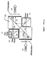
- an exemplary color management system 200 includes a light separator 220, a compensating prism group 240, and means 270 for forming a comprehensive light output 290.
- light separator 220 is positioned to receive a light input 210 comprising a first component and a second component.
- Light separator 220 is configured for separating said first component from said second component and emitting a first light beam 221 comprising said first component and a second light beam 222 comprising said second component.
- light separator 220 may comprise a polarizing beamsplitter configured for separating light oriented in a first plane from light oriented in a second plane and emitting a first light beam comprising light oriented in the first plane and a second light beam comprising light oriented in the second plane.
- compensating prism group 240 is positioned to receive first light beam 221, and the compensating prism group 240 is configured for transmitting the first light beam 221 to be received by a first microdisplay 231.
- compensating prism group 240 is configured for receiving a modified first light beam from the first microdisplay 231 and emitting a compensated light output 282.
- compensated light output 282 comprises the modified first light beam and compensates for an optical aberration induced by the light separator 220.
- compensating prism group 240 comprises a pair of prism compensators. It should be noted that these prism compensators are separated by an air gap. The size of the air gap depends upon the thickness and orientation of the light separator, typically lying being between one and four millimeters, and in an exemplary embodiment, being substantially 2.5 millimeters. Further, the air gap is configured for compensating for one or more optical aberrations, for example using the teachings of US patent No. 5,327,289. In accordance with another exemplary embodiment of the present invention, as shown in Figure 4, compensating prism group 240 may exhibit a tilted orientation. For example, compensating prism group may be oriented at an angle of between -30 degrees and +30 degrees.
- compensating prism group may be oriented at an angle of approximately 15 degrees.
- compensating prism group 240 may comprise a tilted compensator plate 469 that exhibits a tilted orientation.
- tilted compensator plate may be oriented at an angle of between -30 degrees and +30 degrees.
- tilted compensator plate may be oriented at an angle of approximately 15 degrees.
- compensating prism group may be configured to exhibit an equivalent optical path length substantially equal to an that of the polarizing beamsplitter.
- the invention also includes means 270 for forming a comprehensive light output from the compensated light output 282 and a complementary light output 222 comprising the second light beam 222.
- the means 270 for forming a comprehensive light output 290 comprise a polarizing beamsplitter 270, which may be the same element, and serve the same function, as the light separator 220.
- the term "filter” refers to an optical filter configured to discriminate (i.e., block or permit to pass or alter the polarization properties of light flux based on physical characteristics of the light, such as wavelength, orientation, polarization, or flash or field rate) and may be constructed using any technique known in the art such as, for example, embedding an optically active material such as a spectrally sensitive optical retardation film in or on an otherwise transparent substrate or placing a plurality of very thin wires in parallel orientation to one another leaving thin gaps through which light may pass to produce polarized light.
- an optically active material such as a spectrally sensitive optical retardation film in or on an otherwise transparent substrate
- placing a plurality of very thin wires in parallel orientation to one another leaving thin gaps through which light may pass to produce polarized light such as, for example, embedding an optically active material such as a spectrally sensitive optical retardation film in or on an otherwise transparent substrate or placing a plurality of very thin wires in parallel orientation to one another leaving thin gaps through which light
- filters configured for discriminating light based upon its physical characteristics include dichroic plates manufactured by OCLI of Santa Rosa, California and Unaxis of Liechtenstein, ColorSelect filters manufactured by ColorLink of Boulder, Colorado, and ProFlux polarizers and polarizing beamsplitters manufactured by Moxtek of Orem Utah.
- the light separator may be either a dichroic mirror or a polarizing beamsplitter.
- the first light beam may be received by the compensating prism group after being reflected by a polarizing beamsplitter, wherein the second light beam does not encounter the polarizing beamsplitter before being received by the image assimilator, and wherein the image assimilator comprises a filter for selectively rotating a component as well as a polarizing beamsplitter.
- the light separator may comprise a plurality of dichroic mirrors
- filter 215 is configured for receiving a linear polarized light input 210 and selectively rotating the polarization component of the light input 210 to produce a light input 217 comprising polarized light oriented in a first plane and polarized light oriented in a second plane.
- the polarized light oriented in the first plane comprises a first color component, such as green light; the polarized light oriented in the second plane comprises both a second color component and a third color component such as red and blue light.
- Polarizing beamsplitter 220 is positioned to receive the first polarized light output 217 from the first filter 215. It should be noted that a polarizing beam splitter 220 is a device configured to separate an incipient beam of light into two emergent linear polarized beams of light. As such, polarizing beamsplitter 220 may comprise a dichroic mirror having a coating configured to separate light into components of different colors. For example a typical coating may be a thin film dielectric coating. Alternatively, polarizing beamsplitter 220 may be a dielectric beamsplitter having a coating configured to separate light into different components base upon color or polarization.
- polarizing beamsplitter 220 may comprise two or more polarizing beamsplitters 321, 322 having their active surfaces facing substantially away from one another so as to further improve contrast and minimize stress birefringence such as that caused by uneven thermal loading.
- the plurality of polarizing beamsplitters 321, 322 optionally may be tilted with respect to one another to compensate for any offset between the associated light beams, such as that which may be caused by the finite and/or differing thickness of each of the polarizing beamsplitters.
- polarizing beamsplitter may comprise a single component having active polarizing beamsplitter surfaces on both sides.
- An example of such a polarizing beamsplitter would be an optically transmissive subtrate with Proflux TM polarizing beamsplitter surfaces on both surfaces.
- polarizing beamsplitter 220 is configured for separating the polarized light oriented in the first plane from the polarized light oriented in the second plane.
- polarizing beamsplitter 220 may be configured to emit in a first direction the polarized light oriented in the first plane and to emit in a second direction the polarized light oriented in the second plane, wherein the second direction is substantially orthogonal to the first direction.
- polarizing beamsplitter 220 may be configured to transmit the polarized light oriented in the second plane and to reflect the polarized light oriented in the first plane.
- polarizing beamsplitter 220 may be configured to reflect the polarized light oriented in the second plane and to transmit the polarized light oriented in the first plane.
- a plurality of fold mirrors may be employed to direct the various light beams between the elements of the color management system.
- a fold mirror refers to any reflective surface capable of reflecting light.
- fold mirror may be a aluminized mirror or an enhanced silver mirror as produced by Unaxis company of Liechtenstein.
- polarizing beamsplitter 320 may comprises a pair of polarizing beamsplitters 321, 322 having their active surfaces 331, 332 facing substantially away from one another, or a single polarizing beamsplitter component with active surfaces on both sides.
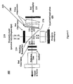
- image assimilator 550 may be positioned to receive from polarizing beamsplitter 220 polarized light oriented in the second plane.
- Image assimilator 550 may be configured for separating the second component from the third component and transmitting the second component to be received by a second microdisplay 532 and the third component to be received by a third microdisplay 533.
- image assimilator 550 may be further configured for receiving a modified second component from the second microdisplay 532 and receiving a modified third component from the third microdisplay 533.
- the image assimilator 550 may be configured to emit an assimilated light output 685 to be received by the polarizing beamsplitter 270, the assimilated light output comprising the modified second component and the modified third component.
- the equivalent optical path length associated with the glass or other optical material of the image assimilator 550 may be determined so that compensating characteristics may be incorporated into appropriate system elements such as compensating prism group 240.
- image assimilator 550 comprises a dichroic prism.
- image assimilator 450 may be a substantially equal path length prism.
- image assimilator 550 may comprise a polarizing filter for producing a differentiated light output comprising the second component and the third component, where the orientation of the second component is rotated to be orthogonal to the orientation of the third component.
- the image assimilator 550 further comprises a second polarizing beamsplitter positioned to receive from the polarizing filter the differentiated light output. This second polarizing beamsplitter is configured for separating the second component from the third component before transmitting the second component to be received by the second microdisplay and before transmitting the third component to be received by the third microdisplay.
- Compensating prism group 240 is positioned to receive the light oriented in the first plane from the polarizing beamsplitter 220.
- Compensating prism group 240 may comprise a pair of prism compensators and is configured to transmit a first component to be received by a first microdisplay and for receiving a modified first component from the first microdisplay.
- compensating prism group 240 is configured to emit a light output, which comprises the modified first component oriented in the second plane, to be received by the polarizing beamsplitter 220.
- compensating prism group 240 is configured to exhibit an equivalent optical path length substantially equal to that of the image assimilator 550.
- the prism compensators of compensating prism group 240 are arranged to be separated by an air gap configured to compensate for one or more optical aberrations produced by the polarizing beamsplitter 220.
- compensating prism group 240 may exhibit a tilted orientation such that its surface facing polarizing beamsplitter 220 is tilted with respect to a plane that lies orthogonally to the most direct path from compensating prism group 240 to polarizing beamsplitter 220.
- compensating prism group 240 may further comprise a tilted compensator plate exhibiting a tilted orientation such that its surface facing polarizing beamsplitter 220 is tilted with respect to a plane that lies orthogonally to the most direct path from tilted compensator plate to polarizing beamsplitter 220.
- the output may be further enhanced by an output filter and or an analyzer positioned to receive the modified light outputs from image assimilator 550 and compensating prism group 240 and to further modify the light to produce polarized light oriented in a single plane, i.e., substantially linearly polarized light, which may be accomplished by rotating the polarization axis of one or more of the light beams.
- the color management system 200 may comprise an analyzer positioned to receive the light emitted from this second filter so as to produce a sharpened comprehensive light output having an improved contrast relative to the light emitted from the second filter.
- the analyzer may be configured for removing light of a predetermined wavelength from the light beam, depending on the characteristics of the filters (i.e., the color selective retardation elements).
- the light beam emitted from the color management system 200 may be magnified through a projection lens for projection of an image.
- a color management system may improve its ability to handle increased light flux requirements while maintaining or decreasing physical size by incorporating a plurality of field lenses positioned to receive and focus the component light beams so as to reduce the diameter of those light beams. Still further, as shown in Figure 8, the system may comprise one or more retarder plates positioned to receive and improve light beams prior to their receipt by the blue and/or red microdisplays.
- color management system 200 may include one or more field lens 610, each lens 610 positioned to receive a linearly polarized beam of light and to focus it prior to receipt of a light beam by a microdisplay and/or after transmission by a microdisplay.
- the light beam may be focused into a more compact output beam, enabling effective use of smaller projection lenses while maintaining equivalent or even increased levels of light flux.
- the filter 215 receives a substantially linearly polarized light input 210 and selectively rotates a component of the polarized light input to emit light oriented in two planes 217.
- the polarizing beamsplitter 220 receives the bi-oriented light 217 and separates it into two substantially linearly polarized light outputs, one comprising a single component and the other comprising two components.
- the image assimilator 550 receives from the polarizing beamsplitter 220 the output light having two components and further separates the light into two light outputs, each comprising one of the two components.
- the image assimilator 550 then transmits each of the light outputs to corresponding microdisplays 532 and 533 and receives a modified output from each of the microdisplays. Finally, the image assimilator 550 produces an output comprising the modified outputs from the microdisplays.
- the compensating prism group 240 receives the single color light output from the polarizing beamsplitter 220 and transmits the light to another corresponding microdisplay 231. Then, the compensating prism group 240 receives a modified light output 259 from the microdisplay 231 and transmits it to be combined with the light output from the image assimilator 550.
- the color management system 200 of the instant invention may be adapted for use in a one panel system as depicted in Figure 2, in a dual panel system as illustrated in Figure 4, or in a three panel system, as illustrated in Figures 5 through 9, by appropriate replacement of image assimilator 550 with compensating prism groups.
- the system of the present invention may be implemented as a pass through system 900, wherein spatial information may be imparted on each of the three light beams 901, 902, and 903 by a green transmissive light valve 931, and a blue transmissive light valve 932, and a red transmissive light valve 933, prior to recombination through two polarizing beamsplitters 920 and 970.
- an exemplary color management system includes a light separator 220 comprising a first dichroic mirror 921 and a second dichroic mirror 922, wherein said first dichroic mirror 921 is positioned to receive said light input and is configured for separating said first component from said second component and emitting a first light beam 903 comprising said first component and a second light beam 989 comprising said second component, wherein said second dichroic mirror 922 is positioned to receive said second light beam 989 and is configured for separating said second component from said third component and emitting a refined second light beam 902 comprising said second component and a third light beam 901 comprising said third component, wherein said first light beam 903 is to be received by a first polarizer 913 configured for producing a first polarized light beam, said refined second light beam 902 is to be received by a second polarizer 912 configured for producing a second polarized light beam, and said third light beam 901 is to be received by a third polarizer 911 configured for producing
- said compensating prism group 940 emits a compensated output to be combined, by beamsplitter 970, with an assimilated output produced by the polarizing beamsplitter 920, which comprises the polarized blue light beam and the polarized red light beam.
- the output from beamsplitter 920 which comprises the polarized blue light beam and the polarized red light beam, passes through a color select filter and a cleanup polarizer before being combined with the output of beamsplitter 970 and being transmitted to a projection lens to be output to projected image.
- the present invention utilizes both polarization dependent elements and dichroic elements to split an input light into a plurality of color bands upon which spatial information may be superimposed by a corresponding plurality of microdisplays, the modified color bands being recombined to produce a full color projected image.
Landscapes
- Engineering & Computer Science (AREA)
- Multimedia (AREA)
- Signal Processing (AREA)
- Optical Elements Other Than Lenses (AREA)
- Projection Apparatus (AREA)
- Closed-Circuit Television Systems (AREA)
Claims (42)
- Système de gestion chromatique comprenant :un séparateur de lumière (220) destiné à recevoir une entrée de lumière (210) comprenant une première composante et une seconde composante, dans lequel ledit séparateur de lumière est configuré pour séparer ladite première composante de ladite seconde composante et émettre un premier faisceau lumineux (221) comprenant ladite première composante et un second faisceau lumineux (222) comprenant ladite seconde composante ; etun groupe de prismes de compensation (240) caractérisé en ce que :ledit séparateur de lumière comprend un séparateur de faisceau polarisant à plaque positionné dans une orientation inclinée ; et ledit groupe de prismes de compensation comprend deux compensateurs à prisme ou davantage séparés par un intervalle d'air positionnés pour recevoir ledit premier faisceau lumineux en vue de transmettre ledit premier faisceau lumineux destiné à être reçu par un premier écran miniature (231), recevoir un premier faisceau lumineux modifié venant dudit premier écran miniature, et émettre une sortie de lumière compensée (282) ; dans lequel ledit intervalle d'air est configuré pour compenser une aberration optique induite par ledit séparateur de lumière incliné.
- Système de gestion chromatique de la revendication 1, dans lequel ladite entrée de lumière comprend une lumière polarisée orientée dans un premier plan et une lumière polarisée orientée dans un second plan, et dans lequel ledit séparateur de lumière comprend un séparateur de faisceau polarisant configuré pour séparer ladite lumière orientée dans ledit premier plan de ladite lumière orientée dans ledit second plan et émettre un premier faisceau lumineux comprenant ladite lumière orientée dans ledit premier plan et un second faisceau lumineux comprenant ladite lumière orientée dans ledit second plan.
- Système de gestion chromatique de la revendication 2, comprenant en outre un séparateur de faisceau polarisant configuré pour former une sortie de lumière globale venant de ladite sortie de lumière compensée et une sortie de lumière complémentaire comprenant ledit second faisceau lumineux.
- Système de gestion chromatique de la revendication 1, dans lequel ledit groupe de prismes de compensation comprend une paire de compensateurs à prisme.
- Système de gestion chromatique de la revendication 1, dans lequel ledit groupe de prismes de compensation présente une orientation inclinée.
- Système de gestion chromatique de la revendication 1, dans lequel ledit groupe de prismes de compensation comprend en outre une plaque de compensateur inclinée présentant une orientation inclinée.
- Système de gestion chromatique de la revendication 2, dans lequel ledit groupe de prismes de compensation est configuré pour présenter une longueur de trajet optique équivalent du compensateur essentiellement égale à une longueur de trajet optique équivalent dudit séparateur dé faisceau polarisant.
- Système de gestion chromatique de la revendication 2, dans lequel ledit séparateur de faisceau polarisant comprend une paire de séparateurs de faisceaux polarisants ayant leurs surfaces actives orientées vers des directions essentiellement opposées l'une par rapport à l'autre.
- Système de gestion chromatique de la revendication 8, dans lequel les séparateurs de faisceaux polarisants de ladite paire sont inclinés l'un par rapport à l'autre.
- Système de gestion chromatique de la revendication 1, comprenant en outre une lentille de projection destinée à recevoir ladite sortie de lumière compensée et à projeter ladite sortie de lumière compensée pour afficher une image.
- Système de gestion chromatique de la revendication 1, comprenant en outre un prisme (450) à longueur de trajet essentiellement égale positionné pour recevoir ledit second faisceau lumineux (222) ; dans lequel ledit prisme d'égale longueur de trajet est configuré pour transmettre ledit second faisceau lumineux destiné à être reçu par un écran miniature, recevoir un second faisceau lumineux modifié venant dudit écran miniature, et émettre une sortie de lumière corrigée comprenant ledit second faisceau lumineux modifié.
- Système de gestion chromatique de la revendication 11, dans lequel ledit groupe (240) de prismes de compensation est configuré pour présenter une longueur de trajet optique équivalent du compensateur essentiellement égale à une longueur de trajet optique équivalent d'une combinaison dudit prisme d'égale longueur de trajet et dudit séparateur de faisceau polarisant.
- Système de gestion chromatique de la revendication 1, dans lequel ladite première composante comprend le rouge.
- Système de gestion chromatique de la revendication 1, dans lequel ladite seconde composante comprend le bleu et le vert.
- Système de gestion chromatique de la revendication 1, comprenant en outre un second écran miniature, un troisième écran miniature et un assimilateur d'image (550, 920) positionné pour recevoir ledit second faisceau lumineux (222), dans lequel ledit second faisceau lumineux comprend en outre une troisième composante ; dans lequel ledit assimilateur d'image est un dispositif destiné à séparer ladite seconde composante de ladite troisième composante, émettre un troisième faisceau lumineux comprenant ladite seconde composante et émettre un quatrième faisceau lumineux comprenant ladite troisième composante, et ledit assimilateur d'image est en outre configuré pour recevoir un troisième faisceau lumineux modifié venant dudit second écran miniature et recevoir un quatrième faisceau lumineux modifié venant dudit troisième écran miniature ; et émettre une lumière comprenant ledit troisième faisceau lumineux modifié et ledit quatrième faisceau lumineux modifié.
- Système de gestion chromatique de la revendication 15, dans lequel ledit groupe de prismes de compensation est configuré pour présenter une longueur de trajet optique équivalent du compensateur essentiellement égale à une longueur de trajet optique équivalent d'une combinaison dudit assimilateur d'image et dudit séparateur de faisceau polarisant.
- Système de gestion chromatique de la revendication 15, dans lequel ledit assimilateur d'image comprend un prisme dichroïque.
- Système de gestion chromatique de la revendication 3, comprenant en outre un filtre de sortie positionné pour recevoir ladite sortie de lumière compensée, dans lequel ledit filtre de sortie est configuré pour produire une sortie de lumière compensée filtrée comprenant une lumière orientée dans un seul plan.
- Système de gestion chromatique de la revendication 18, dans lequel ledit filtre de sortie est configuré pour faire tourner ladite sortie de lumière compensée.
- Système de gestion chromatique de la revendication 18, dans lequel ledit filtre de sortie est configuré pour faire tourner ladite sortie de lumière complémentaire.
- Système de gestion chromatique de la revendication 18, comprenant en outre un analyseur positionné pour recevoir ladite sortie de lumière compensée filtrée, dans lequel ledit analyseur est configuré pour produire une sortie de lumière compensée rendue plus nette ayant un contraste amélioré par rapport à ladite sortie de lumière compensée filtrée.
- Système de gestion chromatique de la revendication 21, dans lequel ledit analyseur est configuré pour enlever une lumière d'une longueur d'onde déterminée de ladite sortie de lumière compensée filtrée.
- Système de gestion chromatique de la revendication 3, comprenant en outre un analyseur positionné pour recevoir ladite sortie de lumière complémentaire, dans lequel ledit analyseur est configuré pour agir en sorte que ladite sortie de lumière complémentaire présente un contraste amélioré.
- Système de gestion chromatique de la revendication 15, dans lequel ladite première composante comprend le vert.
- Système de gestion chromatique de la revendication 15, dans lequel ladite seconde composante comprend le bleu.
- Système de gestion chromatique de la revendication 15, dans lequel ladite troisième composante comprend le rouge.
- Système de gestion chromatique de la revendication 1, dans lequel ledit séparateur de lumière comprend un filtre de lumière d'entrée configuré pour recevoir une entrée de lumière et faire tourner sélectivement une composante de ladite entrée de lumière en vue de produire une entrée de lumière polarisée comprenant une lumière orientée dans un premier plan et une lumière orientée dans un second plan, ledit séparateur de lumière comprenant en outre un séparateur de faisceau polarisant configuré pour séparer ladite lumière orientée dans ledit premier plan de ladite lumière orientée dans ledit second plan et émettre un premier faisceau lumineux comprenant ladite lumière orientée dans ledit premier plan et un second faisceau lumineux comprenant ladite lumière orientée dans ledit second plan.
- Système de gestion chromatique de la revendication 1, dans lequel ledit séparateur de lumière comprend un miroir dichroïque configuré pour séparer ladite première composante de ladite seconde composante.
- Système de gestion chromatique de la revendication 1, comprenant en outre une ou plusieurs lentilles de champ positionnées pour recevoir ledit premier faisceau lumineux avant sa réception par ledit premier écran miniature, dans lequel la ou lesdites lentilles de champ sont configurées pour diminuer un diamètre de section transversale dudit premier faisceau lumineux.
- Système de gestion chromatique de la revendication 15, comprenant en outre une ou plusieurs lentilles de champ positionnées pour recevoir ledit troisième faisceau lumineux avant sa réception par ledit écran miniature, dans lequel la ou lesdites lentilles de champ sont configurées pour diminuer un diamètre de section transversale dudit second faisceau lumineux.
- Système de gestion chromatique de la revendication 30, comprenant en outre une ou plusieurs lentilles de champ positionnées pour recevoir ledit quatrième faisceau lumineux avant sa réception par ledit troisième écran miniature, dans lequel la ou lesdites lentilles de champ sont configurées pour diminuer un diamètre de section transversale dudit troisième faisceau lumineux.
- Système de gestion chromatique de la revendication 15, ledit assimilateur d'image comprenant en outre un filtre d'entrée de l'assimilateur configuré pour recevoir ledit second faisceau lumineux et faire tourner sélectivement une composante dudit second faisceau lumineux en vue de produire un faisceau lumineux polarisé comprenant une lumière orientée dans un premier plan et une lumière orientée dans un second plan, dans lequel ledit assimilateur d'image comprend un séparateur de faisceau polarisant configuré pour séparer ladite seconde composante de ladite troisième composante en séparant ladite lumière orientée dans ledit premier plan de ladite lumière orientée dans ledit second plan.
- Système de gestion chromatique de la revendication 11, comprenant en outre une plaque retardatrice positionnée pour recevoir ledit second faisceau lumineux venant dudit prisme d'égale longueur de trajet et pour émettre un second faisceau lumineux augmenté destiné à être reçu par ledit écran miniature.
- Système de gestion chromatique de la revendication 15, comprenant en outre une plaque retardatrice positionnée pour recevoir ledit troisième faisceau lumineux destiné à être reçu par ledit second écran miniature et/ou une plaque retardatrice positionnée pour recevoir ledit quatrième faisceau lumineux destiné à être reçu par ledit troisième écran miniature.
- Système de gestion chromatique comprenant :un séparateur de lumière (921) destiné à recevoir une entrée de lumière comprenant une première composante et une seconde composante, dans lequel ledit séparateur de lumière est configuré pour séparer ladite première composante de ladite seconde composante et émettre un premier faisceau lumineux (903) comprenant ladite première composante et un second faisceau lumineux (989) comprenant ladite seconde composante ; etun groupe de prismes de compensation (940)dans lequel ledit système de gestion chromatique est
caractérisé en ce que :ledit séparateur de lumière comprend un premier miroir dichroïque (921) et un second miroir dichroïque (922), dans lequel ledit premier miroir dichroïque (921) est positionné pour recevoir ladite entrée de lumière et est configuré pour séparer ladite première composante de ladite seconde composante et émettre ledit premier faisceau lumineux (903) comprenant ladite première composante et ledit second faisceau lumineux (989) comprenant ladite seconde composante, dans lequel ledit second miroir dichroïque (922) est positionné pour recevoir ledit second faisceau lumineux (989), ledit second faisceau lumineux comprenant en outre une troisième composante, et est configuré pour séparer ladite seconde composante de ladite troisième composante et émettre un troisième faisceau lumineux (901) comprenant ladite seconde composante et un quatrième faisceau lumineux comprenant ladite troisième composante (902), dans lequel ledit premier faisceau lumineux (903) est destiné à être reçu par un premier polariseur (913) configuré pour produire un premier faisceau lumineux polarisé, ledit quatrième faisceau lumineux est destiné à être reçu par un second polariseur (912) configuré pour produire un second faisceau lumineux polarisé, et ledit troisième faisceau lumineux est destiné à être reçu par un troisième polariseur (911) configuré pour produire un troisième faisceau lumineux polarisé ;ledit système de gestion chromatique comprenant en outre :dans lequel ledit groupe (940) de prismes de compensation comprend deux compensateurs à prisme ou davantage séparés par un intervalle d'air positionnés pour recevoir ledit faisceau lumineux vert polarisé et configuré pour émettre une sortie de lumière compensée ; dans lequel ledit intervalle d'air est configuré pour compenser une aberration optique induite par ledit séparateur de lumière.un modulateur de lumière rouge (933) positionné pour recevoir ledit premier faisceau lumineux polarisé et configuré pour émettre un faisceau lumineux rouge polarisé ;un modulateur de lumière bleue (932) positionné pour recevoir ledit second faisceau lumineux polarisé et configuré pour émettre un faisceau lumineux bleu polarisé ;un dispositif optique (920) destiné à recevoir ledit faisceau lumineux rouge polarisé et ledit faisceau lumineux bleu polarisé et émettre une lumière comprenant ledit faisceau lumineux rouge polarisé et ledit faisceau lumineux bleu polarisé ; etun modulateur de lumière verte (931) positionné pour recevoir ledit troisième faisceau lumineux polarisé et configuré pour émettre un faisceau lumineux vert polarisé destiné à être reçu par ledit groupe (940) de prismes de compensation ; - Système de gestion chromatique de la revendication 15, dans lequel ledit assimilateur d'image comprend en outre un filtre polarisant configuré pour produire une sortie de lumière différenciée comprenant ladite seconde composante et ladite troisième composante ; dans lequel une orientation de ladite seconde composante est tournée pour être orthogonale à une orientation de ladite troisième composante ; dans lequel ledit assimilateur d'image comprend un séparateur de faisceau polarisant intégré positionné pour recevoir dudit filtre polarisant ladite sortie de lumière différentiée ; et dans lequel ledit séparateur de faisceau polarisant intégré est configuré pour séparer ladite seconde composante de ladite troisième composante, émettre ledit second faisceau lumineux comprenant ladite seconde composante, et émettre ledit troisième faisceau lumineux distinct comprenant ladite troisième composante.
- Système de gestion chromatique de la revendication 2, dans lequel ledit séparateur de faisceau polarisant de séparation est configuré pour émettre dans une première direction ledit premier faisceau lumineux et pour émettre dans une seconde direction ledit second faisceau lumineux, ladite seconde direction étant essentiellement orthogonale à ladite première direction.
- Système de gestion chromatique de la revendication 2, dans lequel ledit séparateur de faisceau polarisant de séparation est configuré pour transmettre ledit second faisceau lumineux et réfléchir ledit premier faisceau lumineux.
- Procédé destiné à fournir une gestion chromatique pour un système de projection convenant pour projeter des niveaux de flux lumineux supérieurs à 500 lumens, le procédé comprenant les étapes consistant à :recevoir une entrée de lumière (210) comprenant une première composante et une seconde composante, séparer ladite première composante de ladite seconde composante et émettre un premier faisceau lumineux (221) comprenant ladite première composante et un second faisceau lumineux (222) comprenant ladite seconde composante ; etrecevoir ledit premier faisceau lumineux, transmettre ledit premier faisceau lumineux destiné à être reçu par un premier écran miniature (231), recevoir un premier faisceau lumineux modifié venant dudit premier écran miniature, faire passer ledit premier faisceau lumineux modifié à travers un groupe de prismes de compensation et émettre une sortie de lumière compensée (282), dans lequel ladite sortie de lumière compensée comprend ledit premier faisceau lumineux modifié et présente une caractéristique de compensation ;ledit procédé étant caractérisé par l'étape consistant à :utiliser un séparateur de faisceau polarisant à plaque positionné dans une orientation inclinée pour séparer ladite première composante de ladite seconde composante ;ledit groupe de prismes de compensation comprenant deux compensateurs à prisme ou davantage séparés par un intervalle d'air, dans lequel ladite sortie de lumière compensée compense une aberration induite par ledit séparateur de faisceau polarisant à plaque inclinée et une longueur de trajet optique équivalente d'un groupe (240) de prismes de compensation.
- Système de gestion chromatique selon la revendication 1, dans lequel le séparateur de lumière comprend plusieurs séparateurs de faisceaux polarisants (321,322) inclinés l'un par rapport à l'autre et ayant des surfaces actives (331,332) orientées pour avoir des directions essentiellement opposées l'une par rapport à l'autre en vue de compenser tout écart entre la première composante et une seconde composante causé par l'épaisseur de chacun des séparateurs de faisceaux polarisants à plaques.
- Procédé de la revendication 39 comprenant en outre les étapes consistant à recevoir ledit second faisceau lumineux, émettre ledit second faisceau lumineux destiné à être reçu par un second écran miniature, recevoir une second faisceau lumineux modifié venant dudit écran miniature, faire passer ledit second faisceau lumineux modifié à travers un prisme (450) d'égale longueur de trajet et émettre une sortie de lumière corrigée qui présente une caractéristique corrigée due audit prisme (450) d'égale longueur de trajet ; et
recevoir ladite sortie de lumière corrigée et ladite sortie de lumière compensée (282) et émettre une sortie de lumière globale (290) comprenant ladite sortie de lumière corrigée et ladite sortie de lumière compensée. - Procédé de la revendication 39, dans lequel le second faisceau lumineux comprend en outre une troisième composante et le procédé comprend en outre les étapes consistant à :séparer ladite seconde composante de ladite troisième composante ;émettre un troisième faisceau lumineux comprenant ladite seconde composante et émettre un quatrième faisceau lumineux comprenant ladite troisième composante ; dans lequel ledit troisième faisceau lumineux est destiné à être reçu par un second écran miniature et ledit quatrième faisceau lumineux est destiné à être reçu par un troisième écran miniature ;assimiler (550) un troisième faisceau lumineux modifié reçu depuis ledit second écran miniature avec un quatrième faisceau lumineux modifié reçu depuis ledit troisième écran miniature pour produire une sortie de lumière assimilée (222) ; etrecevoir ladite sortie de lumière assimilée (222) et ladite sortie de lumière compensée (282) et émettre une sortie de lumière globale (290) comprenant ladite sortie de lumière assimilée et ladite sortie de lumière compensée.
Applications Claiming Priority (3)
| Application Number | Priority Date | Filing Date | Title |
|---|---|---|---|
| US31007701P | 2001-08-06 | 2001-08-06 | |
| US310077P | 2001-08-06 | ||
| PCT/US2002/025101 WO2003015420A1 (fr) | 2001-08-06 | 2002-08-06 | Systeme de gestion chromatique |
Publications (2)
| Publication Number | Publication Date |
|---|---|
| EP1417844A1 EP1417844A1 (fr) | 2004-05-12 |
| EP1417844B1 true EP1417844B1 (fr) | 2006-09-27 |
Family
ID=23200904
Family Applications (1)
| Application Number | Title | Priority Date | Filing Date |
|---|---|---|---|
| EP02752734A Expired - Lifetime EP1417844B1 (fr) | 2001-08-06 | 2002-08-06 | Systeme de gestion chromatique |
Country Status (8)
| Country | Link |
|---|---|
| US (2) | US6851812B2 (fr) |
| EP (1) | EP1417844B1 (fr) |
| JP (1) | JP2004538527A (fr) |
| KR (1) | KR20040028986A (fr) |
| CN (1) | CN100450189C (fr) |
| AT (1) | ATE341161T1 (fr) |
| DE (1) | DE60215025T2 (fr) |
| WO (1) | WO2003015420A1 (fr) |
Families Citing this family (18)
| Publication number | Priority date | Publication date | Assignee | Title |
|---|---|---|---|---|
| CN1249485C (zh) * | 2001-09-04 | 2006-04-05 | 佳能株式会社 | 色分解光学系统、图象显示光学系统和投影式图象显示装置 |
| US6961179B2 (en) * | 2001-11-30 | 2005-11-01 | Colorlink, Inc. | Compensated color management systems and methods |
| JP3489582B2 (ja) * | 2002-03-29 | 2004-01-19 | ソニー株式会社 | 画像表示装置 |
| US6758565B1 (en) * | 2003-03-20 | 2004-07-06 | Eastman Kodak Company | Projection apparatus using telecentric optics |
| US6935746B2 (en) * | 2003-04-15 | 2005-08-30 | Infocus Corporation | Method and apparatus for reducing scattered light in a projection system |
| ITTO20030676A1 (it) * | 2003-09-05 | 2005-03-06 | Sim2 Multimedia Spa | Sistema di illuminamento per videoproiettore che utilizza |
| JP2005189635A (ja) * | 2003-12-26 | 2005-07-14 | Hitachi Ltd | 投射型映像表示装置及びそれに用いる光学ユニット |
| JP4432602B2 (ja) * | 2004-04-28 | 2010-03-17 | 日本ビクター株式会社 | 投射型表示装置 |
| US7147332B2 (en) | 2004-07-21 | 2006-12-12 | 3M Innovative Properties Company | Projection system with scrolling color illumination |
| EP1853968A2 (fr) * | 2005-03-04 | 2007-11-14 | Colorlink, Inc. | Systeme de projection a quatre panneaux |
| US7445341B2 (en) * | 2005-09-21 | 2008-11-04 | 3M Innovative Properties Company | Four panel liquid crystal display system |
| JP5127143B2 (ja) * | 2006-02-09 | 2013-01-23 | キヤノン株式会社 | 色分解光学系および画像投射装置 |
| WO2009139798A1 (fr) * | 2008-05-15 | 2009-11-19 | 3M Innovative Properties Company | Élément optique et combineur de couleurs |
| US9203513B2 (en) * | 2008-05-15 | 2015-12-01 | Teledyne Scientific & Imaging, Llc | SNR enhancement in modulating retroreflector optical communication links |
| JP2012509506A (ja) * | 2008-11-19 | 2012-04-19 | スリーエム イノベイティブ プロパティズ カンパニー | 偏光変換を行う色合成器 |
| CN103207507B (zh) | 2012-01-11 | 2015-07-08 | 中强光电股份有限公司 | 光源模组与投影装置 |
| CN112255863B (zh) * | 2020-10-30 | 2021-08-31 | 山西傲维光视光电科技有限公司 | 一种激光影视摄影照明灯具光路结构 |
| DE102022103459A1 (de) | 2022-02-15 | 2023-08-17 | Carl Zeiss Microscopy Gmbh | Strahlteilerbaugruppe, verfahren zu deren dimensionierung und mikroskop |
Family Cites Families (61)
| Publication number | Priority date | Publication date | Assignee | Title |
|---|---|---|---|---|
| US3637308A (en) * | 1970-06-11 | 1972-01-25 | Rca Corp | Color correction of prismatic off-axis optical system |
| US3868168A (en) * | 1973-01-16 | 1975-02-25 | American Optical Corp | Combination of birefringent elements for polarizing interferential systems |
| US3982819A (en) * | 1975-05-22 | 1976-09-28 | The United States Of America As Represented By The Secretary Of The Navy | Fluid gap glan-laser prism |
| US4864390A (en) * | 1986-08-22 | 1989-09-05 | North American Philips Corporation | Display system with equal path lengths |
| US4928914A (en) | 1989-02-21 | 1990-05-29 | Peerless Industries, Inc. | Tiltable mounting bracket |
| US5235443A (en) * | 1989-07-10 | 1993-08-10 | Hoffmann-La Roche Inc. | Polarizer device |
| US5231431A (en) * | 1989-11-29 | 1993-07-27 | Canon Kabushiki Kaisha | Projection type display apparatus |
| US5315330A (en) | 1989-12-21 | 1994-05-24 | Sharp Kabushiki Kaisha | Projection type display apparatus |
| JPH04180010A (ja) * | 1990-11-15 | 1992-06-26 | Fuji Photo Optical Co Ltd | 光束分割プリズム |
| US5268775A (en) * | 1991-02-19 | 1993-12-07 | Hughes-Jvc Technology Corporation | Contrast enhancement and ghost elimination, for reflective light valve system |
| US5127617A (en) | 1991-05-30 | 1992-07-07 | Peerless Industries, Inc. | Swivel mounting assembly for television and the like |
| US5383641A (en) | 1992-10-27 | 1995-01-24 | Peerless Industries, Inc. | Television support member security mounting assembly |
| US5552922A (en) * | 1993-04-12 | 1996-09-03 | Corning Incorporated | Optical system for projection display |
| US5374968A (en) * | 1993-11-08 | 1994-12-20 | Greyhawk Systems, Inc. | Optics for a single-lens video projector with color-specific polarization channels |
| EP0658794B1 (fr) | 1993-12-17 | 2002-09-11 | Matsushita Electric Industrial Co., Ltd. | Dispositif de projection à cristal liquide et dispositif d'affichage à cristal liquide |
| KR100236107B1 (ko) | 1994-03-09 | 1999-12-15 | 전주범 | 투사형 화상표시장치(projection display system) |
| US5487524A (en) | 1994-04-21 | 1996-01-30 | Peerless Industries, Inc. | Mounting assembly with forced absorption characteristics |
| EP0758460B1 (fr) * | 1994-05-06 | 2001-10-17 | Koninklijke Philips Electronics N.V. | Dispositif de combinaison de faisceaux et appareil de projection d'images en couleur pourvu de ce dispositif |
| DE69416840T2 (de) * | 1994-06-17 | 1999-07-29 | Thomson-Csf, Paris | Flüssigkristallprojektor mit holographischer filtervorrichtung |
| EP0722253A3 (fr) * | 1995-01-10 | 1996-10-30 | Ibm | Arrangements pour des dispositifs d'affichage par projection utilisant des valves optiques en réflexion |
| US6183091B1 (en) * | 1995-04-07 | 2001-02-06 | Colorlink, Inc. | Color imaging systems and methods |
| JP3113169B2 (ja) * | 1995-04-24 | 2000-11-27 | 富士写真光機株式会社 | 非点収差補正素子 |
| JPH08327964A (ja) * | 1995-06-02 | 1996-12-13 | Matsushita Electric Ind Co Ltd | 投写型画像表示装置 |
| US5621486A (en) * | 1995-06-22 | 1997-04-15 | International Business Machines Corporation | Efficient optical system for a high resolution projection display employing reflection light valves |
| US5775665A (en) | 1996-09-25 | 1998-07-07 | Peerless Industries | Security mounting assembly |
| JP3414164B2 (ja) * | 1996-10-31 | 2003-06-09 | ミノルタ株式会社 | 液晶プロジェクタ |
| JP3690006B2 (ja) * | 1996-10-31 | 2005-08-31 | ソニー株式会社 | 映像投射装置 |
| EP0841821A3 (fr) | 1996-11-06 | 2000-01-12 | Canon Kabushiki Kaisha | Appareil de projection |
| JP3444521B2 (ja) * | 1997-06-20 | 2003-09-08 | シャープ株式会社 | 投影型画像表示装置 |
| US5790910A (en) | 1997-08-04 | 1998-08-04 | Peerless Industries, Inc. | Camera mounting apparatus |
| USD400085S (en) | 1997-08-04 | 1998-10-27 | Peerless Industries | Camera mount |
| JPH1164852A (ja) * | 1997-08-21 | 1999-03-05 | Hitachi Ltd | 投射型液晶表示装置 |
| US6046858A (en) | 1997-10-16 | 2000-04-04 | Aurora Systems, Inc. | Light separation and recombination system for an off-axis projector |
| US6273568B1 (en) | 1998-02-05 | 2001-08-14 | Canon Kabushiki Kaisha | Projection apparatus |
| US6176586B1 (en) * | 1998-03-24 | 2001-01-23 | Minolta Co., Ltd. | Projection display apparatus |
| US6231190B1 (en) * | 1998-06-22 | 2001-05-15 | Texas Instruments Incorporated | Color correction filter for displays |
| JP2000081569A (ja) * | 1998-07-03 | 2000-03-21 | Sekinosu Kk | 投影レンズ装置 |
| US6513934B1 (en) * | 1999-02-17 | 2003-02-04 | Canon Kabushiki Kaisha | Projection apparatus and observation apparatus |
| JP2000347177A (ja) * | 1999-03-29 | 2000-12-15 | Minolta Co Ltd | 表示光学装置及びそれを用いたプロジェクター表示装置 |
| JP3370010B2 (ja) * | 1999-03-31 | 2003-01-27 | 三洋電機株式会社 | 液晶プロジェクタ装置 |
| EP1181616A4 (fr) | 1999-04-21 | 2006-04-26 | 3M Innovative Properties Co | Systemes optiques pour afficheurs a cristaux liquides reflechissants |
| US6234634B1 (en) * | 1999-07-28 | 2001-05-22 | Moxtek | Image projection system with a polarizing beam splitter |
| US6309071B1 (en) | 1999-08-04 | 2001-10-30 | Sharp Laboratories Of America, Inc. | Liquid crystal projection display system |
| IL132928A0 (en) * | 1999-11-14 | 2001-03-19 | Unic View Ltd | Thermally stable birefringent prism assembly |
| US6375330B1 (en) | 1999-12-30 | 2002-04-23 | Gain Micro-Optics, Inc. | Reflective liquid-crystal-on-silicon projection engine architecture |
| EP1143744B1 (fr) | 2000-03-17 | 2008-09-24 | Hitachi, Ltd. | Dispositif d'affichage d'image |
| US6661475B1 (en) * | 2000-03-23 | 2003-12-09 | Infocus Corporation | Color video projection system employing reflective liquid crystal display device |
| JP3768381B2 (ja) | 2000-05-11 | 2006-04-19 | 株式会社日立製作所 | 液晶プロジェクタ |
| JP2002049094A (ja) * | 2000-08-04 | 2002-02-15 | Minolta Co Ltd | プリズムシステムおよび投射型映像表示装置 |
| KR100370658B1 (ko) | 2000-12-22 | 2003-02-05 | 삼성전기주식회사 | 색 분리 합성 장치 |
| TW483532U (en) | 2001-02-06 | 2002-04-11 | Delta Electronics Inc | Improvement on color management system of liquid-crystal-display projector |
| JP2002229125A (ja) * | 2001-02-06 | 2002-08-14 | Canon Inc | 投射型画像表示装置および画像表示システム |
| US6585378B2 (en) * | 2001-03-20 | 2003-07-01 | Eastman Kodak Company | Digital cinema projector |
| US6457831B1 (en) * | 2001-04-17 | 2002-10-01 | Prokia Technology Co., Ltd. | Projection display using reflective light modulators |
| USD480100S1 (en) | 2001-06-07 | 2003-09-30 | Peerless Industries, Inc. | Projector mount |
| US6545804B2 (en) | 2001-06-13 | 2003-04-08 | Prokia Technology Co., Ltd. | Projection display with two reflective light valves |
| US6384972B1 (en) | 2001-06-13 | 2002-05-07 | Prokia Technology Co., Ltd. | Projection display with three polarization beam splitter prisms |
| USD478088S1 (en) | 2002-10-10 | 2003-08-05 | Peerless Industries, Inc. | Table top stand |
| USD489599S1 (en) | 2003-05-23 | 2004-05-11 | Peerless Industries, Inc. | Wall mounting system |
| USD488708S1 (en) | 2003-05-23 | 2004-04-20 | Peerless Industries, Inc. | Mounting system |
| USD491747S1 (en) | 2003-06-23 | 2004-06-22 | Peerless Industries, Inc. | Display stand |
-
2002
- 2002-08-06 KR KR10-2004-7001824A patent/KR20040028986A/ko not_active Ceased
- 2002-08-06 AT AT02752734T patent/ATE341161T1/de not_active IP Right Cessation
- 2002-08-06 US US10/213,505 patent/US6851812B2/en not_active Expired - Fee Related
- 2002-08-06 WO PCT/US2002/025101 patent/WO2003015420A1/fr not_active Ceased
- 2002-08-06 EP EP02752734A patent/EP1417844B1/fr not_active Expired - Lifetime
- 2002-08-06 CN CNB028154959A patent/CN100450189C/zh not_active Expired - Fee Related
- 2002-08-06 JP JP2003520200A patent/JP2004538527A/ja active Pending
- 2002-08-06 DE DE60215025T patent/DE60215025T2/de not_active Expired - Lifetime
-
2004
- 2004-12-23 US US11/022,247 patent/US6971747B2/en not_active Expired - Fee Related
Also Published As
| Publication number | Publication date |
|---|---|
| WO2003015420A1 (fr) | 2003-02-20 |
| JP2004538527A (ja) | 2004-12-24 |
| US6971747B2 (en) | 2005-12-06 |
| ATE341161T1 (de) | 2006-10-15 |
| CN1547858A (zh) | 2004-11-17 |
| EP1417844A1 (fr) | 2004-05-12 |
| DE60215025T2 (de) | 2007-05-03 |
| DE60215025D1 (de) | 2006-11-09 |
| US20030025880A1 (en) | 2003-02-06 |
| KR20040028986A (ko) | 2004-04-03 |
| US20050105059A1 (en) | 2005-05-19 |
| CN100450189C (zh) | 2009-01-07 |
| US6851812B2 (en) | 2005-02-08 |
Similar Documents
| Publication | Publication Date | Title |
|---|---|---|
| US6857747B2 (en) | Color management system | |
| US6851812B2 (en) | Color management system | |
| US7023602B2 (en) | Reflective LCD projection system using wide-angle Cartesian polarizing beam splitter and color separation and recombination prisms | |
| US6678015B2 (en) | Color separating/synthesizing apparatus | |
| US6899432B2 (en) | Color management system having a transmissive panel and optical isolator | |
| US6893130B2 (en) | Color management system having a field lens | |
| US5812223A (en) | Color LCD projector with three color separating polarizing beam splitters | |
| US7002752B2 (en) | Three-panel color management systems and methods | |
| WO2000002087A1 (fr) | Systeme de projection d'images | |
| US6945654B2 (en) | Color management system having a prism to compensate for optical aberrations and to enhance contrast | |
| US6982829B1 (en) | Prism assembly with cholesteric reflectors | |
| US20020089679A1 (en) | Color separating/synthesizing apparatus | |
| US7347561B2 (en) | Image display device | |
| KR100429213B1 (ko) | 프로젝터의 광학계 | |
| TW589903B (en) | Color management system | |
| JP2006507525A (ja) | 3パネル式色管理システムおよび方法 | |
| WO2005057939A1 (fr) | Procede et systeme destines a guider une lumiere dans un projecteur polychrome |
Legal Events
| Date | Code | Title | Description |
|---|---|---|---|
| PUAI | Public reference made under article 153(3) epc to a published international application that has entered the european phase |
Free format text: ORIGINAL CODE: 0009012 |
|
| 17P | Request for examination filed |
Effective date: 20040223 |
|
| AK | Designated contracting states |
Kind code of ref document: A1 Designated state(s): AT BE BG CH CY CZ DE DK EE ES FI FR GB GR IE IT LI LU MC NL PT SE SK TR |
|
| AX | Request for extension of the european patent |
Extension state: AL LT LV MK RO SI |
|
| 17Q | First examination report despatched |
Effective date: 20040623 |
|
| RAP1 | Party data changed (applicant data changed or rights of an application transferred) |
Owner name: JDS UNIPHASE CORPORATION |
|
| GRAP | Despatch of communication of intention to grant a patent |
Free format text: ORIGINAL CODE: EPIDOSNIGR1 |
|
| GRAS | Grant fee paid |
Free format text: ORIGINAL CODE: EPIDOSNIGR3 |
|
| GRAA | (expected) grant |
Free format text: ORIGINAL CODE: 0009210 |
|
| AK | Designated contracting states |
Kind code of ref document: B1 Designated state(s): AT BE BG CH CY CZ DE DK EE ES FI FR GB GR IE IT LI LU MC NL PT SE SK TR |
|
| PG25 | Lapsed in a contracting state [announced via postgrant information from national office to epo] |
Ref country code: IT Free format text: LAPSE BECAUSE OF FAILURE TO SUBMIT A TRANSLATION OF THE DESCRIPTION OR TO PAY THE FEE WITHIN THE PRESCRIBED TIME-LIMIT;WARNING: LAPSES OF ITALIAN PATENTS WITH EFFECTIVE DATE BEFORE 2007 MAY HAVE OCCURRED AT ANY TIME BEFORE 2007. THE CORRECT EFFECTIVE DATE MAY BE DIFFERENT FROM THE ONE RECORDED. Effective date: 20060927 Ref country code: CZ Free format text: LAPSE BECAUSE OF FAILURE TO SUBMIT A TRANSLATION OF THE DESCRIPTION OR TO PAY THE FEE WITHIN THE PRESCRIBED TIME-LIMIT Effective date: 20060927 Ref country code: AT Free format text: LAPSE BECAUSE OF FAILURE TO SUBMIT A TRANSLATION OF THE DESCRIPTION OR TO PAY THE FEE WITHIN THE PRESCRIBED TIME-LIMIT Effective date: 20060927 Ref country code: LI Free format text: LAPSE BECAUSE OF FAILURE TO SUBMIT A TRANSLATION OF THE DESCRIPTION OR TO PAY THE FEE WITHIN THE PRESCRIBED TIME-LIMIT Effective date: 20060927 Ref country code: FI Free format text: LAPSE BECAUSE OF FAILURE TO SUBMIT A TRANSLATION OF THE DESCRIPTION OR TO PAY THE FEE WITHIN THE PRESCRIBED TIME-LIMIT Effective date: 20060927 Ref country code: BE Free format text: LAPSE BECAUSE OF FAILURE TO SUBMIT A TRANSLATION OF THE DESCRIPTION OR TO PAY THE FEE WITHIN THE PRESCRIBED TIME-LIMIT Effective date: 20060927 Ref country code: NL Free format text: LAPSE BECAUSE OF FAILURE TO SUBMIT A TRANSLATION OF THE DESCRIPTION OR TO PAY THE FEE WITHIN THE PRESCRIBED TIME-LIMIT Effective date: 20060927 Ref country code: CH Free format text: LAPSE BECAUSE OF FAILURE TO SUBMIT A TRANSLATION OF THE DESCRIPTION OR TO PAY THE FEE WITHIN THE PRESCRIBED TIME-LIMIT Effective date: 20060927 Ref country code: SK Free format text: LAPSE BECAUSE OF FAILURE TO SUBMIT A TRANSLATION OF THE DESCRIPTION OR TO PAY THE FEE WITHIN THE PRESCRIBED TIME-LIMIT Effective date: 20060927 |
|
| REG | Reference to a national code |
Ref country code: GB Ref legal event code: FG4D |
|
| REG | Reference to a national code |
Ref country code: CH Ref legal event code: EP |
|
| REG | Reference to a national code |
Ref country code: IE Ref legal event code: FG4D |
|
| REF | Corresponds to: |
Ref document number: 60215025 Country of ref document: DE Date of ref document: 20061109 Kind code of ref document: P |
|
| PG25 | Lapsed in a contracting state [announced via postgrant information from national office to epo] |
Ref country code: SE Free format text: LAPSE BECAUSE OF FAILURE TO SUBMIT A TRANSLATION OF THE DESCRIPTION OR TO PAY THE FEE WITHIN THE PRESCRIBED TIME-LIMIT Effective date: 20061227 Ref country code: DK Free format text: LAPSE BECAUSE OF FAILURE TO SUBMIT A TRANSLATION OF THE DESCRIPTION OR TO PAY THE FEE WITHIN THE PRESCRIBED TIME-LIMIT Effective date: 20061227 Ref country code: BG Free format text: LAPSE BECAUSE OF FAILURE TO SUBMIT A TRANSLATION OF THE DESCRIPTION OR TO PAY THE FEE WITHIN THE PRESCRIBED TIME-LIMIT Effective date: 20061227 |
|
| PG25 | Lapsed in a contracting state [announced via postgrant information from national office to epo] |
Ref country code: ES Free format text: LAPSE BECAUSE OF FAILURE TO SUBMIT A TRANSLATION OF THE DESCRIPTION OR TO PAY THE FEE WITHIN THE PRESCRIBED TIME-LIMIT Effective date: 20070107 |
|
| NLV1 | Nl: lapsed or annulled due to failure to fulfill the requirements of art. 29p and 29m of the patents act | ||
| PG25 | Lapsed in a contracting state [announced via postgrant information from national office to epo] |
Ref country code: PT Free format text: LAPSE BECAUSE OF FAILURE TO SUBMIT A TRANSLATION OF THE DESCRIPTION OR TO PAY THE FEE WITHIN THE PRESCRIBED TIME-LIMIT Effective date: 20070313 |
|
| REG | Reference to a national code |
Ref country code: CH Ref legal event code: PL |
|
| EN | Fr: translation not filed | ||
| PLBE | No opposition filed within time limit |
Free format text: ORIGINAL CODE: 0009261 |
|
| STAA | Information on the status of an ep patent application or granted ep patent |
Free format text: STATUS: NO OPPOSITION FILED WITHIN TIME LIMIT |
|
| 26N | No opposition filed |
Effective date: 20070628 |
|
| PG25 | Lapsed in a contracting state [announced via postgrant information from national office to epo] |
Ref country code: FR Free format text: LAPSE BECAUSE OF FAILURE TO SUBMIT A TRANSLATION OF THE DESCRIPTION OR TO PAY THE FEE WITHIN THE PRESCRIBED TIME-LIMIT Effective date: 20070525 Ref country code: MC Free format text: LAPSE BECAUSE OF NON-PAYMENT OF DUE FEES Effective date: 20070831 Ref country code: GR Free format text: LAPSE BECAUSE OF FAILURE TO SUBMIT A TRANSLATION OF THE DESCRIPTION OR TO PAY THE FEE WITHIN THE PRESCRIBED TIME-LIMIT Effective date: 20061228 |
|
| PG25 | Lapsed in a contracting state [announced via postgrant information from national office to epo] |
Ref country code: EE Free format text: LAPSE BECAUSE OF FAILURE TO SUBMIT A TRANSLATION OF THE DESCRIPTION OR TO PAY THE FEE WITHIN THE PRESCRIBED TIME-LIMIT Effective date: 20060927 |
|
| PG25 | Lapsed in a contracting state [announced via postgrant information from national office to epo] |
Ref country code: IE Free format text: LAPSE BECAUSE OF NON-PAYMENT OF DUE FEES Effective date: 20070806 |
|
| PG25 | Lapsed in a contracting state [announced via postgrant information from national office to epo] |
Ref country code: FR Free format text: LAPSE BECAUSE OF FAILURE TO SUBMIT A TRANSLATION OF THE DESCRIPTION OR TO PAY THE FEE WITHIN THE PRESCRIBED TIME-LIMIT Effective date: 20060927 |
|
| PG25 | Lapsed in a contracting state [announced via postgrant information from national office to epo] |
Ref country code: CY Free format text: LAPSE BECAUSE OF FAILURE TO SUBMIT A TRANSLATION OF THE DESCRIPTION OR TO PAY THE FEE WITHIN THE PRESCRIBED TIME-LIMIT Effective date: 20060927 Ref country code: LU Free format text: LAPSE BECAUSE OF NON-PAYMENT OF DUE FEES Effective date: 20070806 |
|
| PG25 | Lapsed in a contracting state [announced via postgrant information from national office to epo] |
Ref country code: TR Free format text: LAPSE BECAUSE OF FAILURE TO SUBMIT A TRANSLATION OF THE DESCRIPTION OR TO PAY THE FEE WITHIN THE PRESCRIBED TIME-LIMIT Effective date: 20060927 |
|
| PGFP | Annual fee paid to national office [announced via postgrant information from national office to epo] |
Ref country code: GB Payment date: 20090825 Year of fee payment: 8 |
|
| PGFP | Annual fee paid to national office [announced via postgrant information from national office to epo] |
Ref country code: DE Payment date: 20090827 Year of fee payment: 8 |
|
| GBPC | Gb: european patent ceased through non-payment of renewal fee |
Effective date: 20100806 |
|
| REG | Reference to a national code |
Ref country code: DE Ref legal event code: R119 Ref document number: 60215025 Country of ref document: DE Effective date: 20110301 |
|
| PG25 | Lapsed in a contracting state [announced via postgrant information from national office to epo] |
Ref country code: DE Free format text: LAPSE BECAUSE OF NON-PAYMENT OF DUE FEES Effective date: 20110301 |
|
| PG25 | Lapsed in a contracting state [announced via postgrant information from national office to epo] |
Ref country code: GB Free format text: LAPSE BECAUSE OF NON-PAYMENT OF DUE FEES Effective date: 20100806 |