EP1418007A2 - Herausziehbarer Sprühkopf mit einer mit einem einzigen Betätigungsknopf versehenen Umschaltvorrichtung - Google Patents
Herausziehbarer Sprühkopf mit einer mit einem einzigen Betätigungsknopf versehenen Umschaltvorrichtung Download PDFInfo
- Publication number
- EP1418007A2 EP1418007A2 EP20030256519 EP03256519A EP1418007A2 EP 1418007 A2 EP1418007 A2 EP 1418007A2 EP 20030256519 EP20030256519 EP 20030256519 EP 03256519 A EP03256519 A EP 03256519A EP 1418007 A2 EP1418007 A2 EP 1418007A2
- Authority
- EP
- European Patent Office
- Prior art keywords
- trigger
- diverter
- toggle
- spray head
- spool
- Prior art date
- Legal status (The legal status is an assumption and is not a legal conclusion. Google has not performed a legal analysis and makes no representation as to the accuracy of the status listed.)
- Withdrawn
Links
Images




Classifications
-
- E—FIXED CONSTRUCTIONS
- E03—WATER SUPPLY; SEWERAGE
- E03C—DOMESTIC PLUMBING INSTALLATIONS FOR FRESH WATER OR WASTE WATER; SINKS
- E03C1/00—Domestic plumbing installations for fresh water or waste water; Sinks
- E03C1/02—Plumbing installations for fresh water
- E03C1/08—Jet regulators or jet guides, e.g. anti-splash devices
-
- B—PERFORMING OPERATIONS; TRANSPORTING
- B05—SPRAYING OR ATOMISING IN GENERAL; APPLYING FLUENT MATERIALS TO SURFACES, IN GENERAL
- B05B—SPRAYING APPARATUS; ATOMISING APPARATUS; NOZZLES
- B05B1/00—Nozzles, spray heads or other outlets, with or without auxiliary devices such as valves, heating means
- B05B1/14—Nozzles, spray heads or other outlets, with or without auxiliary devices such as valves, heating means with multiple outlet openings; with strainers in or outside the outlet opening
- B05B1/16—Nozzles, spray heads or other outlets, with or without auxiliary devices such as valves, heating means with multiple outlet openings; with strainers in or outside the outlet opening having selectively- effective outlets
- B05B1/1609—Nozzles, spray heads or other outlets, with or without auxiliary devices such as valves, heating means with multiple outlet openings; with strainers in or outside the outlet opening having selectively- effective outlets with a selecting mechanism comprising a lift valve
- B05B1/1618—Nozzles, spray heads or other outlets, with or without auxiliary devices such as valves, heating means with multiple outlet openings; with strainers in or outside the outlet opening having selectively- effective outlets with a selecting mechanism comprising a lift valve where said valve is a double-seat lift valve
-
- B—PERFORMING OPERATIONS; TRANSPORTING
- B05—SPRAYING OR ATOMISING IN GENERAL; APPLYING FLUENT MATERIALS TO SURFACES, IN GENERAL
- B05B—SPRAYING APPARATUS; ATOMISING APPARATUS; NOZZLES
- B05B1/00—Nozzles, spray heads or other outlets, with or without auxiliary devices such as valves, heating means
- B05B1/14—Nozzles, spray heads or other outlets, with or without auxiliary devices such as valves, heating means with multiple outlet openings; with strainers in or outside the outlet opening
- B05B1/18—Roses; Shower heads
- B05B1/188—Roses; Shower heads with user-actuated controlling members
- B05B1/1882—Roses; Shower heads with user-actuated controlling members actuated by a linear movement, e.g. push buttons
-
- B—PERFORMING OPERATIONS; TRANSPORTING
- B05—SPRAYING OR ATOMISING IN GENERAL; APPLYING FLUENT MATERIALS TO SURFACES, IN GENERAL
- B05B—SPRAYING APPARATUS; ATOMISING APPARATUS; NOZZLES
- B05B1/00—Nozzles, spray heads or other outlets, with or without auxiliary devices such as valves, heating means
- B05B1/14—Nozzles, spray heads or other outlets, with or without auxiliary devices such as valves, heating means with multiple outlet openings; with strainers in or outside the outlet opening
- B05B1/18—Roses; Shower heads
- B05B1/188—Roses; Shower heads with user-actuated controlling members
- B05B1/1887—Roses; Shower heads with user-actuated controlling members actuated by a pivoting movement
-
- E—FIXED CONSTRUCTIONS
- E03—WATER SUPPLY; SEWERAGE
- E03C—DOMESTIC PLUMBING INSTALLATIONS FOR FRESH WATER OR WASTE WATER; SINKS
- E03C1/00—Domestic plumbing installations for fresh water or waste water; Sinks
- E03C1/02—Plumbing installations for fresh water
- E03C1/04—Water-basin installations specially adapted to wash-basins or baths
-
- E—FIXED CONSTRUCTIONS
- E03—WATER SUPPLY; SEWERAGE
- E03C—DOMESTIC PLUMBING INSTALLATIONS FOR FRESH WATER OR WASTE WATER; SINKS
- E03C1/00—Domestic plumbing installations for fresh water or waste water; Sinks
- E03C1/02—Plumbing installations for fresh water
- E03C1/04—Water-basin installations specially adapted to wash-basins or baths
- E03C1/0404—Constructional or functional features of the spout
-
- B—PERFORMING OPERATIONS; TRANSPORTING
- B05—SPRAYING OR ATOMISING IN GENERAL; APPLYING FLUENT MATERIALS TO SURFACES, IN GENERAL
- B05B—SPRAYING APPARATUS; ATOMISING APPARATUS; NOZZLES
- B05B1/00—Nozzles, spray heads or other outlets, with or without auxiliary devices such as valves, heating means
- B05B1/14—Nozzles, spray heads or other outlets, with or without auxiliary devices such as valves, heating means with multiple outlet openings; with strainers in or outside the outlet opening
- B05B1/18—Roses; Shower heads
-
- B—PERFORMING OPERATIONS; TRANSPORTING
- B05—SPRAYING OR ATOMISING IN GENERAL; APPLYING FLUENT MATERIALS TO SURFACES, IN GENERAL
- B05B—SPRAYING APPARATUS; ATOMISING APPARATUS; NOZZLES
- B05B1/00—Nozzles, spray heads or other outlets, with or without auxiliary devices such as valves, heating means
- B05B1/14—Nozzles, spray heads or other outlets, with or without auxiliary devices such as valves, heating means with multiple outlet openings; with strainers in or outside the outlet opening
- B05B1/18—Roses; Shower heads
- B05B1/188—Roses; Shower heads with user-actuated controlling members
- B05B1/1896—Roses; Shower heads with user-actuated controlling members located in or on the housing
-
- E—FIXED CONSTRUCTIONS
- E03—WATER SUPPLY; SEWERAGE
- E03C—DOMESTIC PLUMBING INSTALLATIONS FOR FRESH WATER OR WASTE WATER; SINKS
- E03C1/00—Domestic plumbing installations for fresh water or waste water; Sinks
- E03C1/02—Plumbing installations for fresh water
- E03C1/04—Water-basin installations specially adapted to wash-basins or baths
- E03C2001/0415—Water-basin installations specially adapted to wash-basins or baths having an extendable water outlet
-
- E—FIXED CONSTRUCTIONS
- E03—WATER SUPPLY; SEWERAGE
- E03C—DOMESTIC PLUMBING INSTALLATIONS FOR FRESH WATER OR WASTE WATER; SINKS
- E03C2201/00—Details, devices or methods not otherwise provided for
- E03C2201/30—Diverter valves in faucets or taps
-
- Y—GENERAL TAGGING OF NEW TECHNOLOGICAL DEVELOPMENTS; GENERAL TAGGING OF CROSS-SECTIONAL TECHNOLOGIES SPANNING OVER SEVERAL SECTIONS OF THE IPC; TECHNICAL SUBJECTS COVERED BY FORMER USPC CROSS-REFERENCE ART COLLECTIONS [XRACs] AND DIGESTS
- Y10—TECHNICAL SUBJECTS COVERED BY FORMER USPC
- Y10T—TECHNICAL SUBJECTS COVERED BY FORMER US CLASSIFICATION
- Y10T137/00—Fluid handling
- Y10T137/8593—Systems
- Y10T137/86493—Multi-way valve unit
- Y10T137/86879—Reciprocating valve unit
-
- Y—GENERAL TAGGING OF NEW TECHNOLOGICAL DEVELOPMENTS; GENERAL TAGGING OF CROSS-SECTIONAL TECHNOLOGIES SPANNING OVER SEVERAL SECTIONS OF THE IPC; TECHNICAL SUBJECTS COVERED BY FORMER USPC CROSS-REFERENCE ART COLLECTIONS [XRACs] AND DIGESTS
- Y10—TECHNICAL SUBJECTS COVERED BY FORMER USPC
- Y10T—TECHNICAL SUBJECTS COVERED BY FORMER US CLASSIFICATION
- Y10T137/00—Fluid handling
- Y10T137/8593—Systems
- Y10T137/877—With flow control means for branched passages
- Y10T137/87708—With common valve operator
- Y10T137/8778—Spring biased
Definitions
- This invention relates to faucets and is particularly concerned with a faucet having a pullout spray head or wand connected to a flexible water supply tube.
- the spray head can be mounted on a fixed base unit or it can be detached from the base unit and pulled out to allow a user to direct water to any desired location.
- Multiple delivery modes may include a spray mode and a stream mode.
- the spray mode water is discharged in a relatively wide spray pattern comprising a large number of small, individual streams.
- the stream mode water is discharged in a single, relatively narrow, concentrated stream.
- Multiple modes of this type are particularly useful in kitchen faucets, although their use is not limited to kitchens. Lavatories, showers or any other faucet, including a garden hose, may benefit from this feature.
- the present invention is concerned with a pullout spray head which provides multiple water discharge spray patterns or modes and which permits momentary shut off of water flow with a pause button.
- the mode is selected by means of a single action at a single point of actuation. The user is not required to hold the actuating device in place while using the various modes.
- the mode is changed simply by pressing the same button, in the same direction, with each successive actuation of the button changing the discharge mode.
- the spray head will remain in the selected mode until another actuation of the button or until the water is turned off, at which time the spray head reverts to a home position or mode.
- the spray head of the present invention also includes a pause button that momentarily interrupts the water while the pause button is depressed.
- the button must be held in the depressed position to keep the flow interrupted. Release of the pause button reactivates water flow.
- the force necessary to actuate the pause button is independent of the water pressure, within the limits of normal household operating pressures (which range from about 10 psi to 125 psi).
- the pause button is especially useful when the spray head is pulled out because the primary on/off control valve may often be an inconvenient distance from the spray head.
- the pause feature is also useful in two-handle faucet designs where resetting of the hot/cold ratio may also be inconvenient.
- the pause feature is applicable to all discharge modes of the faucet.
- Fig. 1 is a perspective view of a single handle, high arc pull down faucet incorporating the pullout spray head of the present invention.
- Fig. 2 is a schematic section through the faucet of Fig. 1.
- Fig. 3 is an exploded perspective view of the pullout spray head.
- Fig. 4 is a top plan view of the wand body.
- Fig. 5 is a side elevation view of the wand body.
- Fig. 6 is an end elevation view of the wand body.
- Fig. 7 is a bottom plan view of the wand body.
- Fig. 8 is a section taken along line 8-8 of Fig. 6.
- Fig. 9 is a section taken along line 9-9 of Fig. 6.
- Fig. 10 is a section taken along line 10-10 of Fig. 6.
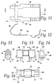
- Fig. 11 is a top plan view of the trigger spring, on an enlarged scale.
- Fig. 12 is a section taken along line 12-12 of Fig. 11.
- Fig. 13 is a front elevation view of the toggle wedge, on an enlarged scale.
- Fig. 13 is an end elevation view of the toggle wedge.
- Fig. 15 is a section taken along line 15-15 of Fig. 13.
- Fig. 16 is a bottom plan view of the toggle wedge.
- Fig. 17 is a schematic vertical section through the spray head assembly, showing the interaction among the trigger, diverter and wand body.
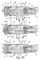
- Fig. 18 is a section through the spray head assembly, showing the diverter in the spray mode position.
- Fig. 19 is a section through the spray head assembly, showing the diverter in the stream mode position.
- Fig. 20 is a section through the spray head assembly, showing the diverter in the stream mode position and the pause button activated.
- Fig. 21 is an enlarged section through the pause button portion of the spray head.
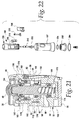
- Fig. 22 is an exploded perspective view of an alternate embodiment of a spray head.
- Fig. 23 is horizontal section through the spray head of Fig. 22.
- Fig. 24 is a vertical section through the spray head of Fig. 22.
- Figs. 1 and 2 illustrate a faucet generally at 10 which incorporates the pullout spray head or wand of the present invention.
- the faucet 10 includes a gooseneck spout 12 and a single handle mixing valve 14, both of which are mounted above a deck, which is shown schematically at 16.
- the pullout spray head 18 is shown in its docked position at the distal end of the spout 12. Below the deck are hot and cold water supply lines 20, 22, a mixed water outlet pipe 24, a transfer line 26, and a mixed water inlet pipe 28.
- a quick connect 30 is connected to the inlet pipe.
- a flexible hose 32 is attached to the quick connect 30 and extends through the hollow interior of the spout to join the spray head 18.
- the hose has a weight 34 on it to assist in drawing the hose back into the spout during docking.
- Fig. 3 illustrates the pullout spray head 18 of the present invention.
- the exterior components include a main cover 36, a trigger cover 38, a ring 40 at the proximal end of the spray head and a tip 42 at the distal end.
- proximal refers to a position or direction toward the portion of the spray head nearest the hose attachment point.
- Distal refers to a position or direction toward the portion of the spray head nearest the water discharge point.
- the exterior parts have suitable decorative finishes.
- the ring 40 is sized to permit it to releasably connect to the end of the spout 12 for the purpose of docking the spray head to the spout.
- the main cover 36 has a slot 44 for receiving the trigger cover 38.
- the trigger cover is made of flexible material and has a trigger dome 46 and a pause dome 48.
- the exterior components surround a wand body 50. Details of the wand body are shown in Figs. 4 - 10.
- the body has an arcuate bottom wall 52 which joins two upstanding, flat side walls 53, 54.
- the side walls have projecting tabs 55 that engage retention slots in the trigger cover 38 to hold the cover in place.
- a floor 56 extends between the lower edges of the two side walls. Thus, the floor 56 forms a chord across the arcuate bottom wall 52, as best seen in Fig. 10. Together the bottom wall and floor define a main water flow path 58.
- the ends of the side walls are joined by front and rear transverse walls 60 and 62.
- the rear transverse wall 62 has a pocket 63 formed just above the floor.
- the front wall has a bore 64 therethrough defined by a sleeve 66.
- the forward or distal end of the sleeve defines a first diverter seat 68.
- These embossments have branch passages 71 therein that are in fluid communication with the bore 64.
- the branch passages have openings in the sides of the body, one of which is shown at 70 in Fig. 5.
- the openings 70 communicate with V-shaped notches 72 cut into threads 74 formed on the exterior of a threaded annular outlet wall 76.
- the outlet wall merges with the front transverse wall 60 and the arcuate bottom wall 52, roughly at the location of an O-ring seal 78.
- a threaded annular inlet wall 80 defining an inlet 82.
- the hose can be attached to the inlet wall.
- the inlet wall is surrounded by a threaded outer sleeve 83 which may be used to attach the wand ring 40.
- the inlet wall 80 preferably may house a check valve 84 and a screen washer 86 (Fig. 3).
- the inlet wall 80 merges with the bottom wall 52, side walls 53, 54 and an upstanding interior wall 88 (Fig. 8). These walls, together with the proximal face of the rear transverse wall 62 define a pause chamber 90.
- the pause chamber has an axis that is generally perpendicular to that of the wand body 50.
- the pause chamber houses the pause button as will be described below.
- a circular valve seat 92 is formed in the walls forming the pause chamber.
- the interior wall 88 has a port 94 through it to provide fluid communication from the inlet 82 to the pause chamber 90. It will be noted that the pause chamber also communicates with the main flow path 58 and thus becomes part of the main flow path.
- the inner surface of the outlet wall 76 has an undercut 95 into which fits a poppet valve seat 96.
- This ringshaped member has a central opening 97.
- the V-shaped opening 97 provides a second outlet from the body, the first outlet being the side openings 70.
- a second diverter seat 98 is formed on the inner surface of the poppet valve seat 96.
- An O-ring 100 placed about the outer circumference of the seat 98 seals against the inner surface of the outlet wall's undercut portion.
- a spray former 102 is attached to the outlet wall 76.
- the spray former has an outer annular skirt 104 with internal threads that engage threads 74. It will be noted in Fig. 18 that the skirt engages a lip on the interior of the wand tip 42 to hold the tip against the wand cover 36.
- the junction between the skirt 104 and the wand body is sealed by an O-ring 78.
- a radial end surface 106 extends from the outer skirt 104 to an inner annular ring 108 which is attached to the end surface so as to be concentric with the skirt. There is a gap between the inner ring 108 and the outer skirt 104 which communicates with a plurality of small individual outlet openings 110 through the end surface 106. These openings produce the spray mode of the spray head 18.
- a face seal 114 is placed between the aerator 112 and the distal radial face of the poppet valve seat 96. This seal prevents leakage from the opening 97 in the poppet valve seat to the gap between the spray former's inner ring 108 and outer skirt 104. Thus, when the spray head is in stream mode, water cannot find its way to the spray mode openings 110.
- a cone spring 116 surrounds the aerator and has its large end bottomed against the end surface 106 of the spray former. The cone spring extends through the opening 97 in poppet valve seat 96 to engage the diverter spool as will be explained below.
- the wand body 50 includes a cavity defined by the side walls 53, 54, floor 56 and transverse walls 62, 64. This cavity is completely isolated from the water flow path.
- a trigger, spring and diverter assembly are disposed in the cavity.
- the diverter assembly includes a spool 118 that is slidably mounted in the sleeve 66 and pocket 63.
- the spool carries a quad cup seal 120 and a face seal 122.
- the face seal is engageable with the first diverter seat 68 and the second diverter seat 98.
- the other end of the spool has a pin 124 extending transversely through the spool.
- the pin pivotally mounts a toggle 126 to the spool.
- the toggle is in the form of a wedge.
- the wedge has two sets of cam faces 128, 129 separated by a central section 130. Two loops 131 underneath the cam faces have bores that allow the loops to fully surround the pin 124.
- the cam faces have grooves 133 in their undersides that partially receive the pin therein.
- the cam faces 128, 129 in an end view of the wedge have a triangular shape with relatively sharp lower corners as at distal corners 132 and proximal corners 134.
- a trigger spring 136 is also mounted in the wand cavity. As seen in Figs. 11 and 12, the spring has two elongated legs 138 joined at one end by an upstanding bail 140 and at the other end by a U-shaped angled portion 142. The bail 140 straddles the pocket 63 while the angled portion fits over the spool 118.
- the legs 138 have notches 144 that engage extensions 145 (Figs. 4 and 8) on the inner surfaces of side walls 53, 54 to fix the longitudinal position of the trigger spring in the wand cavity.
- the floor 56 has wedge-shaped protrusions 147 (Figs. 4 and 8) adjacent the extensions 145. The protrusions 147 engage the underside of the legs near the notches 144 and act as fulcrums.
- the trigger When the trigger is in place it presses down on the angled portion 142 distally of the fulcrums with the result that the portions of the legs proximal of the fulcrums (approximately from the notches 144 to the bail 140) are spaced above the floor and are, in effect, cantilevered from the fulcrums. This is best seen in Fig. 17.
- the legs also have depressions or troughs 146 disposed generally in the vicinity of the toggle wedge 126. The troughs are sized to enable them to be in registration with one of the wedge corners. When that happens one pair of cam corners will engage the legs while the other pair of cam corners will be disengaged from the spring's legs 138. This causes the toggle wedge to flip back and forth, as will be further explained below.
- the trigger is shown at 148. It is pivotally mounted to the wand body by stubshafts 150 that extend into slots in the side walls 54. One of the slots is shown at 152.
- the trigger includes a pushbutton 154 disposed underneath the trigger dome 46 in the trigger cover 38. Underneath the pushbutton are two spaced fingers 156. Each finger is engageable with one of the cam faces 128, 129. The body of the trigger rests on the angled portion 142 of the trigger spring and is biased upwardly by the angled portion. Conversely, the angled portion is pressed down with the resulting cantilevering of the legs as just explained.
- the pause button includes a pause spool 160.
- the pause spool has a series of flanges which form upper, intermediate and lower recesses 162, 164, 166.
- the upper and lower recesses receive quad cup seals 168 while the intermediate recess receives a face seal 170.
- the bottom of the spool 160 has a bore 172 into which fits a spring 174.
- the spring bottoms on the bottom wall which is vented to atmosphere by openings 175 (Fig. 7).
- the top of the spool chamber is vented so there is no build up of any air pressure on either side of the spool as it moves up and down.
- a pause spool guide 176 rests in the upper end of the pause chamber 90 and is sealed thereto by O-ring 178.
- a flange 180 on the spool guide engages the top flange of the upper recess 162 so as to limit upward motion of the pause spool 160.
- the pause spool guide 176 is retained by a U-shaped stop clip 182 that slides through slots 183 (Fig. 8) in the pause chamber walls.
- a flexible cap 184 sits on top of the spool 160 and underneath the pause dome 48 of the trigger cover 38.
- the flange outside diameters of the upper and lower recesses 162, 166 are essentially the same. This is important to maintain evenly balanced hydraulic forces on the pause spool 160. The only unbalanced forces on the spool are those applied by the spring 174 and the user. At the same time the face seal 170 needs to be larger than the quad cup seals in order to enable it to engage the seat 92. This creates an assembly problem as you need to insert the pause spool with a larger central seal into a chamber sized for engagement with two smaller quad cup seals on either side of the larger seal. The pause spool guide solves this problem. The upper portion of the pause chamber is enlarged to allow passage of the face seal 170.
- the pause spool guide fills in the extra space to allow the upper and lower quad cup seals to be the same size. If the spool guide were integral with the spool, the upper seal would have a greater area than the lower seal and the hydraulic forces on the spool would not be balanced. The separate pause spool guide resolves that issue as well as the assembly problem.
- the use, operation and function of the above embodiment are as follows.
- the normal condition of the pause button 158 is shown in Fig. 21.
- the spring 174 urges the spool 160 upwardly so the face seal 170 is spaced from the valve seat 92. Water can flow from the inlet 82 through the port 94 into the pause chamber 90, past the seat 92 and into the main flow path 58. Water pressure is present over the central portion of the spool. Since the seals 168 have equivalent, or nearly equivalent, pressurized areas, the hydraulic forces on the spool are balanced. This allows the return spring 174 to push the spool to the open position regardless of the water pressure.
- the pause button is in the normal, open position.
- the diverter switches flow between two water delivery modes. In this case the modes are stream and spray, although it could be otherwise.
- the diverter starts out in its home position as shown in Fig. 19.
- the spool 118 is retracted so the face seal 122 is engaged with the first diverter seat 68.
- This cuts off flow into the sleeve 66 and thus flow to the branch passage openings 70 is prevented. All the flow is directed out through the poppet valve seat opening 97, into and then out of the aerator 112. This is stream mode.
- the top of the toggle wedge is leaning forwardly, i.e., toward the distal end of the spray head.
- the trigger pivots in a clockwise manner (as seen in Fig. 17) about the stubshafts 150.
- the downward movement of the fingers 156 on the cam surfaces causes the wedge and the spool 118 to slide forwardly.
- the trigger spring 136 remains longitudinally stationary.
- the spring legs flex downwardly as the distal wedge corners 132 drive up out of the troughs 146 and onto the legs 138.
- the proximal wedge corners 134 move out of engagement with the legs and into registration with the troughs.
- the legs act on the distal wedge corners to pivot the toggle wedge 126 clockwise. Now the top of the wedge leans toward the rear of the spray head and the distal surfaces of the cam faces are aligned with the trigger fingers.
- the spool 118 has carried the face seal 122 into engagement with second diverter seat 98 on the poppet valve seat 96, as shown in Fig. 18. This is the spray mode. Water flow through the valve seat 96 is prevented by engagement of the face seal 122 and second diverter seat 98. However, the forward movement of the spool has removed the face seal from the first diverter seat 68 so water can flow into the sleeve 66 and into the branch passages 71 in the embossments 69 and from there out the openings 70. Water will continue from there through the V-shaped notches 72 to the gap between the spray former's outer skirt 104 and inner ring 108. Water ultimately flows out the plurality of outlet openings 110 in spray mode.
- FIG. 22 An alternate embodiment of the spray head is shown generally at 186 in Figs. 22 - 24.
- This embodiment utilizes several components whose functions are identical to those described above but they may be shaped somewhat differently. These include a wand body 188 that has a cavity 190, a main flow path 192 under the cavity and a first diverter seat 194. A second diverter seat 196 is formed in spray former 202. A wand cover 197 surrounds the body 188. A first flow passage for stream mode extends through an aerator 198. A second branch flow passage for stream mode is shown at 200 in Fig. 23.
- a spray former 202 with O-rings 204 is also provided.
- the spray head has a two-piece trigger mechanism including a trigger button 206 and a trigger lever 208.
- a spool driver 210 has first and second cam faces 212 and 214.
- the spool driver 210 is guided in a channel 216 that is formed in the floor of the cavity 190.
- the mode is toggled by the trigger button 206 being depressed which pushes the trigger lever 208 on to one of the spool driver cam faces 212, 214.
- the spool driver is connected to the end of a spool 218 in a manner that allows the spool driver to pivot.
- the spool 218 has an elastomeric face seal 220 that is alternately engageable with one of the first and second diverter seats 194, 196.
- the face seal 220 closes one water path through aerator 198 when in engaging the second diverter seat 196 and closes the other water path 200 when engaging the first diverter seat 194.
- the spool driver 210 has two cam faces 212, 214, one that causes the trigger motion to move the spool driver and spool into a spray position and one that causes the trigger motion to move the spool driver and spool into the stream mode position. Only one of the cam faces is aligned with the trigger mechanism at a time. This alignment is done by the shaped channel 216 that guides and positions the spool driver cam faces appropriately for returning to stream mode when the mechanism is in the spray mode, and returning the mechanism to spray mode when in stream mode. To position the cam faces appropriately it is necessary that the trigger lever be free to pivot side to side so that it maintains contact with the cam face as the spool driver moves through the shaped channel.
- the trigger lever 208 must center itself to the ready position after it has pushed the spool driver to the new mode position, and the trigger button 206 has been released.
- One way to do this is with cantilevered leaf springs on either side of the trigger lever that push it back to center when no other force is on it.
- Another way of centering the trigger lever is to shape the bottom pivoting portion of it and constrain the trigger lever to within the trigger button. In this way when the trigger button is released and the trigger lever rocks back, it is forced to center itself.
- one of the modes is designated a default mode which the diverter take up whenever the water is shut off. This is so a user will know what to expect when the water is next turned on.
- a spray head could have no default mode so whatever mode it was in when water was shut off will be the one it is in when water is turned back on.
Landscapes
- Health & Medical Sciences (AREA)
- Life Sciences & Earth Sciences (AREA)
- Engineering & Computer Science (AREA)
- Hydrology & Water Resources (AREA)
- Public Health (AREA)
- Water Supply & Treatment (AREA)
- Nozzles (AREA)
Applications Claiming Priority (2)
| Application Number | Priority Date | Filing Date | Title |
|---|---|---|---|
| US291157 | 2002-11-08 | ||
| US10/291,157 US7000854B2 (en) | 2002-11-08 | 2002-11-08 | Pullout spray head with single-button mode selector |
Publications (2)
| Publication Number | Publication Date |
|---|---|
| EP1418007A2 true EP1418007A2 (de) | 2004-05-12 |
| EP1418007A3 EP1418007A3 (de) | 2007-02-28 |
Family
ID=32107656
Family Applications (1)
| Application Number | Title | Priority Date | Filing Date |
|---|---|---|---|
| EP20030256519 Withdrawn EP1418007A3 (de) | 2002-11-08 | 2003-10-16 | Herausziehbarer Sprühkopf mit einer mit einem einzigen Betätigungsknopf versehenen Umschaltvorrichtung |
Country Status (6)
| Country | Link |
|---|---|
| US (1) | US7000854B2 (de) |
| EP (1) | EP1418007A3 (de) |
| KR (1) | KR20040041004A (de) |
| CN (1) | CN1498686A (de) |
| CA (1) | CA2446028A1 (de) |
| TW (1) | TW200505581A (de) |
Cited By (10)
| Publication number | Priority date | Publication date | Assignee | Title |
|---|---|---|---|---|
| WO2009102455A1 (en) * | 2008-02-12 | 2009-08-20 | Kohler Co. | Sprayer assembly with simultaneous control of on/off and flow selection |
| US7850098B2 (en) | 2005-05-13 | 2010-12-14 | Masco Corporation Of Indiana | Power sprayer |
| US7909269B2 (en) | 2006-09-19 | 2011-03-22 | Kohler Co. | Faucet spray control assembly |
| US8152078B2 (en) | 2006-10-25 | 2012-04-10 | Masco Corporation Of Indiana | Faucet spray head |
| EP2500103A1 (de) * | 2011-03-14 | 2012-09-19 | Kwc Ag | Umstellhandbrause |
| US8448667B2 (en) | 2009-10-19 | 2013-05-28 | Masco Corporation Of Indiana | Multi-function pull-out wand |
| EP2636804A1 (de) * | 2012-03-05 | 2013-09-11 | Fabrizio Nobili | Sprühkopf für Küche oder Badezimmer |
| GB2486659B (en) * | 2010-12-21 | 2018-10-31 | Norcros Group Holdings Ltd | Fluid flow control device |
| US11267003B2 (en) | 2005-05-13 | 2022-03-08 | Delta Faucet Company | Power sprayer |
| DE102013009194B4 (de) | 2012-06-04 | 2022-10-20 | Xiamen Solex High-Tech Industries Co., Ltd. | Umschaltventilverband mit einer Taste für automatische Rückstellung und Duschkopf mit dem Ventilverband |
Families Citing this family (100)
| Publication number | Priority date | Publication date | Assignee | Title |
|---|---|---|---|---|
| US7114666B2 (en) * | 2002-12-10 | 2006-10-03 | Water Pik, Inc. | Dual massage shower head |
| DE10335652A1 (de) * | 2003-07-29 | 2005-02-24 | Hansgrohe Ag | Halterungsanordnung für eine Brause |
| US7740186B2 (en) | 2004-09-01 | 2010-06-22 | Water Pik, Inc. | Drenching shower head |
| US7343930B2 (en) | 2004-12-03 | 2008-03-18 | Masco Corporation Of Indiana | Sprayer with non-faucet control |
| US20060169801A1 (en) * | 2005-01-28 | 2006-08-03 | Chuanbao Zhu | Faucet side spray assembly |
| GB0507224D0 (en) * | 2005-04-09 | 2005-05-18 | Glaxo Group Ltd | A fluid dispensing device |
| DE102005063387B4 (de) * | 2005-05-28 | 2007-07-19 | Hansa Metallwerke Ag | Sanitärarmatur |
| US7753079B2 (en) | 2005-06-17 | 2010-07-13 | Masco Corporation Of Indiana | Magnetic coupling for sprayheads |
| US7909061B2 (en) | 2005-06-17 | 2011-03-22 | Masco Corporation Of Indiana | Magnetic coupling for sprayheads |
| DE502005004639D1 (de) | 2005-06-24 | 2008-08-21 | Weidmann Plastics Tech Ag | Ventil, insbesondere für eine Sanitärarmatur |
| DE102005059999B4 (de) * | 2005-12-13 | 2017-09-14 | Grohe Ag | Wasserausflussarmatur |
| US7344095B1 (en) * | 2006-01-25 | 2008-03-18 | Da Yuan Sheng Industrial Co., Ltd. | Water sprayer having two water output manners |
| US7871020B2 (en) | 2006-01-26 | 2011-01-18 | Masco Corporation Of Indiana | Faucet spray head with volume control |
| CA2641597C (en) | 2006-02-06 | 2013-11-26 | Masco Corporation Of Indiana | Power sprayer |
| CH698984B1 (de) | 2006-02-09 | 2009-12-31 | Weidmann Plastics Tech Ag | Auszugsbrause. |
| ITMI20060357A1 (it) * | 2006-02-28 | 2007-09-01 | Fabrizio Nobili | Doccetta per lavello con variazione del getto di erogazione e regolazione della portata |
| WO2007124455A2 (en) | 2006-04-20 | 2007-11-01 | Water Pik, Inc. | Converging spray showerhead |
| USD573696S1 (en) | 2006-07-07 | 2008-07-22 | Kohler Co. | Spout |
| US7331536B1 (en) * | 2006-07-14 | 2008-02-19 | Globe Union Industrial Corp. (Guic) | Shower head |
| US7380731B1 (en) * | 2006-09-13 | 2008-06-03 | Da Yuan Sheng Industrial Co., Ltd. | Water sprayer having two water different spraying modes |
| US20080083844A1 (en) * | 2006-10-09 | 2008-04-10 | Water Pik, Inc. | Showerhead attachment assembly |
| US7789326B2 (en) | 2006-12-29 | 2010-09-07 | Water Pik, Inc. | Handheld showerhead with mode control and method of selecting a handheld showerhead mode |
| US8020787B2 (en) | 2006-11-29 | 2011-09-20 | Water Pik, Inc. | Showerhead system |
| USD582521S1 (en) | 2006-12-15 | 2008-12-09 | Newfrey Llc | Sprayhead |
| US8794543B2 (en) | 2006-12-28 | 2014-08-05 | Water Pik, Inc. | Low-speed pulsating showerhead |
| US7770822B2 (en) * | 2006-12-28 | 2010-08-10 | Water Pik, Inc. | Hand shower with an extendable handle |
| USD583015S1 (en) | 2007-01-08 | 2008-12-16 | Newfrey Llc | Sprayhead |
| US7721761B2 (en) * | 2007-01-31 | 2010-05-25 | Masco Corporation Of Indiana | Diverter integrated into a side sprayer |
| US8789218B2 (en) | 2007-05-04 | 2014-07-29 | Water Pik, Inc. | Molded arm for showerheads and method of making same |
| US20100155639A1 (en) * | 2007-07-09 | 2010-06-24 | Zhou Huasong | Switching unit for pushbutton of kitchen water faucet |
| US20090236000A1 (en) | 2008-03-19 | 2009-09-24 | Miller Michael A | Diverter valve with handle |
| CN102037268B (zh) | 2008-05-21 | 2015-09-02 | 印第安纳马斯科公司 | 一体式厨用龙头侧喷射器和分水器 |
| CA2678769C (en) | 2008-09-15 | 2014-07-29 | Water Pik, Inc. | Shower assembly with radial mode changer |
| US20100301144A1 (en) * | 2009-06-01 | 2010-12-02 | William Wray Shepler | Low-Flow Faucet Wand |
| FI121590B (fi) * | 2009-06-30 | 2011-01-31 | Marioff Corp Oy | Suihkutuspää |
| USD625776S1 (en) | 2009-10-05 | 2010-10-19 | Water Pik, Inc. | Showerhead |
| US8851398B2 (en) * | 2009-11-18 | 2014-10-07 | Xiamen Solex High-Tech Industries Co., Ltd. | Overhead shower and its switching method thereof |
| ITMI20100785A1 (it) * | 2010-05-05 | 2011-11-06 | Amfag Spa | Doccetta per lavello da cucina. |
| US8616470B2 (en) | 2010-08-25 | 2013-12-31 | Water Pik, Inc. | Mode control valve in showerhead connector |
| IT1403102B1 (it) * | 2010-12-15 | 2013-10-04 | Amfag S P A Ora Amfag S R L | Doccetta perfezionata per lavello da cucina. |
| USD678467S1 (en) | 2012-01-27 | 2013-03-19 | Water Pik, Inc. | Ring-shaped handheld showerhead |
| USD678463S1 (en) | 2012-01-27 | 2013-03-19 | Water Pik, Inc. | Ring-shaped wall mount showerhead |
| US9273450B2 (en) | 2012-06-22 | 2016-03-01 | Kohler Mira Limited | Plumbing fixture with heating elements |
| CA2820623C (en) | 2012-06-22 | 2017-10-03 | Water Pik, Inc. | Bracket for showerhead with integral flow control |
| US9284723B2 (en) | 2012-07-27 | 2016-03-15 | Kohler Co. | Magnetic docking faucet |
| US9181685B2 (en) | 2012-07-27 | 2015-11-10 | Kohler Co. | Magnetic docking faucet |
| WO2014201420A1 (en) | 2013-06-13 | 2014-12-18 | Water Pik, Inc. | Showerhead with turbine driven shutter |
| USD744611S1 (en) | 2014-06-13 | 2015-12-01 | Water Pik, Inc. | Handheld showerhead |
| USD744064S1 (en) | 2014-06-13 | 2015-11-24 | Water Pik, Inc. | Handheld showerhead |
| USD744614S1 (en) | 2014-06-13 | 2015-12-01 | Water Pik, Inc. | Wall mount showerhead |
| USD744612S1 (en) | 2014-06-13 | 2015-12-01 | Water Pik, Inc. | Handheld showerhead |
| USD745111S1 (en) | 2014-06-13 | 2015-12-08 | Water Pik, Inc. | Wall mount showerhead |
| USD744065S1 (en) | 2014-06-13 | 2015-11-24 | Water Pik, Inc. | Handheld showerhead |
| USD744066S1 (en) | 2014-06-13 | 2015-11-24 | Water Pik, Inc. | Wall mount showerhead |
| US9714507B1 (en) * | 2014-08-27 | 2017-07-25 | Jose L. Snell | Toilet cleaner spray hose and deodorizer |
| CN104315195B (zh) * | 2014-09-30 | 2016-09-07 | 厦门建霖工业有限公司 | 一种两路转换出水系统 |
| CN104265950B (zh) * | 2014-09-30 | 2016-06-08 | 厦门建霖工业有限公司 | 一种出水转换器 |
| CN204328069U (zh) * | 2014-11-17 | 2015-05-13 | 厦门建霖工业有限公司 | 一种新型出水转换器 |
| US9422695B2 (en) * | 2014-12-04 | 2016-08-23 | Gary Wu | Water faucet |
| US10287761B2 (en) * | 2015-08-25 | 2019-05-14 | Globe Union Industrial Corp. | Faucets providing additional control for water flow |
| US10443218B2 (en) * | 2015-08-25 | 2019-10-15 | Globe Union Industrial Corp. | Faucets providing mixed water and air flow |
| US10364557B2 (en) * | 2015-08-25 | 2019-07-30 | Globe Union Industrial Corp. | Faucets providing mixed water and air flow |
| US10245606B2 (en) * | 2015-08-25 | 2019-04-02 | Globe Union Industrial Corp. | Touch spray head |
| TWI567272B (zh) * | 2015-08-25 | 2017-01-21 | Globe Union Ind Corp | Touch nozzle |
| US10329750B2 (en) * | 2015-08-25 | 2019-06-25 | Globe Union Industrial Corp. | Faucets providing water-and-air flow |
| USD786404S1 (en) | 2015-09-22 | 2017-05-09 | Kohler Co. | Faucet |
| USD786405S1 (en) * | 2015-11-23 | 2017-05-09 | Spectrum Brands, Inc. | Faucet |
| USD803981S1 (en) | 2016-02-01 | 2017-11-28 | Water Pik, Inc. | Handheld spray nozzle |
| WO2017136484A1 (en) | 2016-02-01 | 2017-08-10 | Water Pik, Inc. | Handheld pet spray wand |
| US10265710B2 (en) | 2016-04-15 | 2019-04-23 | Water Pik, Inc. | Showerhead with dual oscillating massage |
| USD970684S1 (en) | 2016-04-15 | 2022-11-22 | Water Pik, Inc. | Showerhead |
| CN107755111B (zh) * | 2016-08-18 | 2023-07-07 | 厦门松霖科技股份有限公司 | 止水装置和花洒 |
| CN106362883B (zh) * | 2016-08-30 | 2019-02-12 | 厦门建霖健康家居股份有限公司 | 一种带有暂停水多功能的模块 |
| CN113856927B (zh) | 2016-09-08 | 2023-02-21 | 洁碧有限公司 | 用于淋浴头的暂停组件 |
| DE102017102490A1 (de) * | 2017-02-08 | 2018-08-09 | Holger Pfannschmidt | Vorrichtung zum Reinigen eines Nassrasiererklingenkopfes |
| USD835238S1 (en) * | 2017-03-30 | 2018-12-04 | Blanco Gmbh + Co Kg | Faucet |
| USD835237S1 (en) * | 2017-03-30 | 2018-12-04 | BLANCO GmbH+ Co KG | Faucet |
| USD835239S1 (en) * | 2017-03-30 | 2018-12-04 | Blanco Gmbh + Co Kg | Faucet |
| USD835236S1 (en) * | 2017-03-30 | 2018-12-04 | Blanco Gmbh + Co Kg | Faucet |
| CN107269884B (zh) * | 2017-06-27 | 2023-05-30 | 开平市汉顺洁具实业有限公司 | 一种具有复位功能的出水结构及出水结构的拉出头 |
| USD843549S1 (en) | 2017-07-19 | 2019-03-19 | Water Pik, Inc. | Handheld spray nozzle |
| GB2568271B (en) | 2017-11-09 | 2020-04-22 | Kohler Mira Ltd | A plumbing component for controlling the mixture of two supplies of water |
| USD858714S1 (en) * | 2018-01-08 | 2019-09-03 | Delta Faucet Company | Faucet hub |
| USD872227S1 (en) | 2018-04-20 | 2020-01-07 | Water Pik, Inc. | Handheld spray device |
| CN115672581A (zh) * | 2018-06-29 | 2023-02-03 | 洁碧有限公司 | 用于喷淋头的暂停组件 |
| USD847950S1 (en) * | 2018-11-22 | 2019-05-07 | Xinrui Zhang | Faucet |
| USD849202S1 (en) * | 2018-11-22 | 2019-05-21 | Xinrui Zhang | Faucet |
| USD890884S1 (en) | 2018-12-28 | 2020-07-21 | Spectrum Brands, Inc. | Shower column |
| US11618043B2 (en) | 2019-08-09 | 2023-04-04 | Delta Faucet Company | Flow restricting and diverting manifold for multiple function showerhead systems |
| USD912776S1 (en) * | 2019-09-16 | 2021-03-09 | Zhihua Huang | Faucet |
| US11555298B2 (en) | 2020-01-17 | 2023-01-17 | Delta Faucet Company | Locking side sprayer |
| US11505926B2 (en) | 2020-01-24 | 2022-11-22 | Delta Faucet Company | Multiple function shower systems including consolidated mode switching controls |
| US11668079B2 (en) | 2020-01-24 | 2023-06-06 | Delta Faucet Company | Multiple function shower systems facilitating low actuation force mode switching |
| US12123527B2 (en) * | 2020-11-20 | 2024-10-22 | Beijing Kohler Ltd. | Operation switch, operation mechanism, pull-out operation device, pull-out control mechanism, and pull-out device |
| EP4039371B1 (de) * | 2021-02-03 | 2025-06-18 | Fabrizio Nobili | Ventil für eine handbrause in bad oder küche |
| CN113152597B (zh) * | 2021-04-01 | 2023-01-13 | 浙江凯玛卫浴有限公司 | 一种任意调节流向的水龙头 |
| JP7582894B2 (ja) | 2021-04-07 | 2024-11-13 | 株式会社Kvk | 弁機構及びシャワーヘッド |
| CN114632635B (zh) * | 2022-01-25 | 2023-07-07 | 厦门水蜻蜓卫浴科技有限公司 | 一种出水装置 |
| US12472029B2 (en) * | 2023-12-06 | 2025-11-18 | Cilag Gmbh International | Particulate collector covers |
| CN118950287B (zh) * | 2024-10-15 | 2025-01-24 | 宁波瀚隆洁具有限公司 | 一种花洒及其推拨切换结构 |
Citations (4)
| Publication number | Priority date | Publication date | Assignee | Title |
|---|---|---|---|---|
| US5858215A (en) | 1996-12-06 | 1999-01-12 | Moen Incorporated | Water filter containing faucet and display therefor |
| US6220297B1 (en) | 1999-08-23 | 2001-04-24 | Masco Corporation Of Indiana | Pull-out spray head having reduced play |
| US6290147B1 (en) | 2000-09-19 | 2001-09-18 | Moen Incorporated | Pullout faucet wand button mechanism |
| US6370713B2 (en) | 2000-03-10 | 2002-04-16 | Amfag S.P.A. | Pull-out shower head for kitchen |
Family Cites Families (23)
| Publication number | Priority date | Publication date | Assignee | Title |
|---|---|---|---|---|
| US2314071A (en) | 1941-09-19 | 1943-03-16 | Modern Faucet Co | Pressure control fitting |
| CH481331A (fr) | 1967-10-17 | 1969-11-15 | Kugler Fonderie Robinetterie | Batterie de bain |
| US3656503A (en) * | 1970-05-11 | 1972-04-18 | Irving A Ward | Fluid control valve |
| US3722525A (en) | 1971-04-14 | 1973-03-27 | P Epple | Fluid switching valve |
| US4029119A (en) | 1975-04-30 | 1977-06-14 | Hal Klieves | Valve and valve system |
| DE2739196C2 (de) * | 1977-08-31 | 1982-07-22 | Friedrich Grohe Armaturenfabrik Gmbh & Co, 5870 Hemer | Umschaltventil |
| USRE32981E (en) | 1983-06-30 | 1989-07-11 | Masco Corporation | Anti-siphon and anti-knock diverter valve |
| DE3401352A1 (de) * | 1984-01-17 | 1985-07-18 | Friedrich Grohe Armaturenfabrik Gmbh & Co, 5870 Hemer | Umstellbetaetigungsglied |
| DE3442490A1 (de) * | 1984-11-22 | 1986-05-28 | Knebel & Röttger GmbH & Co, 5860 Iserlohn | Auslauf-rohrleitungsschalter mit einem zulauf und zwei ablaeufen |
| US4934402A (en) | 1988-12-14 | 1990-06-19 | Price Pfister, Inc. | Fluid diverter |
| US4927115A (en) | 1989-05-26 | 1990-05-22 | Masco Corporation Of Indiana | Valve for a hand held spray nozzle |
| CH682838A5 (de) * | 1990-04-06 | 1993-11-30 | Karrer Weber & Cie Ag | Umstellventil mit selbsttätiger Rückstellung. |
| DE9314443U1 (de) * | 1993-09-24 | 1993-12-02 | H. Weidmann Ag, Rapperswil, St. Gallen | Wasserauslauf für eine Sanitärarmatur |
| US5433384A (en) * | 1994-06-24 | 1995-07-18 | Jing Mei Industrial Limited | Push button controlled multifunction shower head |
| US5476225A (en) * | 1994-06-24 | 1995-12-19 | Jing Mei Industrial Limited | Multi spray pattern shower head |
| US5445182A (en) | 1994-08-11 | 1995-08-29 | Sturman; Oded E. | Toggle fluid control valve |
| US5649562A (en) | 1995-06-06 | 1997-07-22 | Sturman; Oded E. | Toggle fluid control valve |
| JP3067979B2 (ja) * | 1995-08-18 | 2000-07-24 | 株式会社喜多村合金製作所 | 吐水ヘッド |
| US6007003C1 (en) * | 1998-10-20 | 2001-06-19 | Yuan Mei Corp | Water amount controlling switch structure of water injection gun |
| US6296011B1 (en) * | 1999-04-14 | 2001-10-02 | Kohler Co. | Fluid valve |
| US6151729A (en) * | 1999-10-28 | 2000-11-28 | Chya Ye Industrial Co., Ltd. | Switch valve for use in a rinsing shower head mounted to a kitchen sink |
| JP4482921B2 (ja) * | 2000-09-18 | 2010-06-16 | Toto株式会社 | 吐水装置 |
| US6659373B1 (en) * | 2001-05-30 | 2003-12-09 | L. R. Nelson | One touch actuated valve |
-
2002
- 2002-11-08 US US10/291,157 patent/US7000854B2/en not_active Expired - Fee Related
-
2003
- 2003-09-29 TW TW092126841A patent/TW200505581A/zh unknown
- 2003-10-15 KR KR1020030071837A patent/KR20040041004A/ko not_active Ceased
- 2003-10-16 EP EP20030256519 patent/EP1418007A3/de not_active Withdrawn
- 2003-10-22 CA CA 2446028 patent/CA2446028A1/en not_active Abandoned
- 2003-10-23 CN CNA200310102560XA patent/CN1498686A/zh active Pending
Patent Citations (4)
| Publication number | Priority date | Publication date | Assignee | Title |
|---|---|---|---|---|
| US5858215A (en) | 1996-12-06 | 1999-01-12 | Moen Incorporated | Water filter containing faucet and display therefor |
| US6220297B1 (en) | 1999-08-23 | 2001-04-24 | Masco Corporation Of Indiana | Pull-out spray head having reduced play |
| US6370713B2 (en) | 2000-03-10 | 2002-04-16 | Amfag S.P.A. | Pull-out shower head for kitchen |
| US6290147B1 (en) | 2000-09-19 | 2001-09-18 | Moen Incorporated | Pullout faucet wand button mechanism |
Cited By (14)
| Publication number | Priority date | Publication date | Assignee | Title |
|---|---|---|---|---|
| US9962718B2 (en) | 2005-05-13 | 2018-05-08 | Delta Faucet Company | Power sprayer |
| US7850098B2 (en) | 2005-05-13 | 2010-12-14 | Masco Corporation Of Indiana | Power sprayer |
| US11267003B2 (en) | 2005-05-13 | 2022-03-08 | Delta Faucet Company | Power sprayer |
| US10618066B2 (en) | 2005-05-13 | 2020-04-14 | Delta Faucet Company | Power sprayer |
| US7909269B2 (en) | 2006-09-19 | 2011-03-22 | Kohler Co. | Faucet spray control assembly |
| US8152078B2 (en) | 2006-10-25 | 2012-04-10 | Masco Corporation Of Indiana | Faucet spray head |
| US9272295B2 (en) | 2008-02-12 | 2016-03-01 | Kohler Co. | Sprayer assembly |
| WO2009102455A1 (en) * | 2008-02-12 | 2009-08-20 | Kohler Co. | Sprayer assembly with simultaneous control of on/off and flow selection |
| US8448667B2 (en) | 2009-10-19 | 2013-05-28 | Masco Corporation Of Indiana | Multi-function pull-out wand |
| GB2486659B (en) * | 2010-12-21 | 2018-10-31 | Norcros Group Holdings Ltd | Fluid flow control device |
| US9027857B2 (en) | 2011-03-14 | 2015-05-12 | Kwc Ag | Switchable hand shower |
| EP2500103A1 (de) * | 2011-03-14 | 2012-09-19 | Kwc Ag | Umstellhandbrause |
| EP2636804A1 (de) * | 2012-03-05 | 2013-09-11 | Fabrizio Nobili | Sprühkopf für Küche oder Badezimmer |
| DE102013009194B4 (de) | 2012-06-04 | 2022-10-20 | Xiamen Solex High-Tech Industries Co., Ltd. | Umschaltventilverband mit einer Taste für automatische Rückstellung und Duschkopf mit dem Ventilverband |
Also Published As
| Publication number | Publication date |
|---|---|
| CA2446028A1 (en) | 2004-05-08 |
| CN1498686A (zh) | 2004-05-26 |
| US20040112985A1 (en) | 2004-06-17 |
| EP1418007A3 (de) | 2007-02-28 |
| US7000854B2 (en) | 2006-02-21 |
| KR20040041004A (ko) | 2004-05-13 |
| TW200505581A (en) | 2005-02-16 |
Similar Documents
| Publication | Publication Date | Title |
|---|---|---|
| US7000854B2 (en) | Pullout spray head with single-button mode selector | |
| US6738996B1 (en) | Pullout spray head with pause button | |
| CN101516520B (zh) | 龙头喷射控制组装件 | |
| US11919017B2 (en) | Water spray gun | |
| US5383604A (en) | Water outlet head for a sanitary fitting | |
| US6085790A (en) | Dual-flow faucet head | |
| US8448667B2 (en) | Multi-function pull-out wand | |
| US8424781B2 (en) | Power sprayer | |
| US9272295B2 (en) | Sprayer assembly | |
| CN219100218U (zh) | 具有多种喷射型式的水龙头 | |
| US11905691B2 (en) | Pivoting spray head faucet | |
| CN113134431B (zh) | 喷洒器组件和操作侧部喷洒器的方法 | |
| US10443218B2 (en) | Faucets providing mixed water and air flow | |
| US12540463B2 (en) | Soap dispenser in a kitchen faucet wand | |
| CA2446038A1 (en) | Pull out spray head with pause button | |
| EP1577016A1 (de) | Brausekopf mit kontinuierlicher Waaserstrahlsteuerung und Umschaltvorrichtung dafür | |
| CA2990926C (en) | Faucets providing mixed water and air flow |
Legal Events
| Date | Code | Title | Description |
|---|---|---|---|
| PUAI | Public reference made under article 153(3) epc to a published international application that has entered the european phase |
Free format text: ORIGINAL CODE: 0009012 |
|
| AK | Designated contracting states |
Kind code of ref document: A2 Designated state(s): AT BE BG CH CY CZ DE DK EE ES FI FR GB GR HU IE IT LI LU MC NL PT RO SE SI SK TR |
|
| AX | Request for extension of the european patent |
Extension state: AL LT LV MK |
|
| PUAL | Search report despatched |
Free format text: ORIGINAL CODE: 0009013 |
|
| AK | Designated contracting states |
Kind code of ref document: A3 Designated state(s): AT BE BG CH CY CZ DE DK EE ES FI FR GB GR HU IE IT LI LU MC NL PT RO SE SI SK TR |
|
| AX | Request for extension of the european patent |
Extension state: AL LT LV MK |
|
| AKX | Designation fees paid | ||
| REG | Reference to a national code |
Ref country code: DE Ref legal event code: 8566 |
|
| STAA | Information on the status of an ep patent application or granted ep patent |
Free format text: STATUS: THE APPLICATION IS DEEMED TO BE WITHDRAWN |
|
| 18D | Application deemed to be withdrawn |
Effective date: 20070829 |