EP1418105A1 - Dispositif et procédé de simulation de la caractéristique d'une pédale - Google Patents
Dispositif et procédé de simulation de la caractéristique d'une pédale Download PDFInfo
- Publication number
- EP1418105A1 EP1418105A1 EP02102535A EP02102535A EP1418105A1 EP 1418105 A1 EP1418105 A1 EP 1418105A1 EP 02102535 A EP02102535 A EP 02102535A EP 02102535 A EP02102535 A EP 02102535A EP 1418105 A1 EP1418105 A1 EP 1418105A1
- Authority
- EP
- European Patent Office
- Prior art keywords
- pedal
- force
- coupled
- pressure reservoir
- target position
- Prior art date
- Legal status (The legal status is an assumption and is not a legal conclusion. Google has not performed a legal analysis and makes no representation as to the accuracy of the status listed.)
- Granted
Links
- 238000000034 method Methods 0.000 title claims abstract description 11
- 230000000295 complement effect Effects 0.000 claims description 17
- 230000001133 acceleration Effects 0.000 claims description 16
- 238000004088 simulation Methods 0.000 claims description 7
- 230000001419 dependent effect Effects 0.000 claims description 3
- 238000004422 calculation algorithm Methods 0.000 abstract description 6
- 238000011161 development Methods 0.000 description 4
- 230000018109 developmental process Effects 0.000 description 4
- 230000007246 mechanism Effects 0.000 description 4
- 230000008878 coupling Effects 0.000 description 3
- 238000010168 coupling process Methods 0.000 description 3
- 238000005859 coupling reaction Methods 0.000 description 3
- 238000006073 displacement reaction Methods 0.000 description 2
- 230000006870 function Effects 0.000 description 2
- 238000005259 measurement Methods 0.000 description 2
- 238000004364 calculation method Methods 0.000 description 1
- 230000000694 effects Effects 0.000 description 1
- 239000002655 kraft paper Substances 0.000 description 1
- 230000008569 process Effects 0.000 description 1
- 230000004044 response Effects 0.000 description 1
- 230000035807 sensation Effects 0.000 description 1
- 230000003068 static effect Effects 0.000 description 1
Images

Classifications
-
- B—PERFORMING OPERATIONS; TRANSPORTING
- B60—VEHICLES IN GENERAL
- B60T—VEHICLE BRAKE CONTROL SYSTEMS OR PARTS THEREOF; BRAKE CONTROL SYSTEMS OR PARTS THEREOF, IN GENERAL; ARRANGEMENT OF BRAKING ELEMENTS ON VEHICLES IN GENERAL; PORTABLE DEVICES FOR PREVENTING UNWANTED MOVEMENT OF VEHICLES; VEHICLE MODIFICATIONS TO FACILITATE COOLING OF BRAKES
- B60T8/00—Arrangements for adjusting wheel-braking force to meet varying vehicular or ground-surface conditions, e.g. limiting or varying distribution of braking force
- B60T8/32—Arrangements for adjusting wheel-braking force to meet varying vehicular or ground-surface conditions, e.g. limiting or varying distribution of braking force responsive to a speed condition, e.g. acceleration or deceleration
- B60T8/34—Arrangements for adjusting wheel-braking force to meet varying vehicular or ground-surface conditions, e.g. limiting or varying distribution of braking force responsive to a speed condition, e.g. acceleration or deceleration having a fluid pressure regulator responsive to a speed condition
- B60T8/40—Arrangements for adjusting wheel-braking force to meet varying vehicular or ground-surface conditions, e.g. limiting or varying distribution of braking force responsive to a speed condition, e.g. acceleration or deceleration having a fluid pressure regulator responsive to a speed condition comprising an additional fluid circuit including fluid pressurising means for modifying the pressure of the braking fluid, e.g. including wheel driven pumps for detecting a speed condition, or pumps which are controlled by means independent of the braking system
- B60T8/4072—Systems in which a driver input signal is used as a control signal for the additional fluid circuit which is normally used for braking
- B60T8/4081—Systems with stroke simulating devices for driver input
- B60T8/409—Systems with stroke simulating devices for driver input characterised by details of the stroke simulating device
-
- B—PERFORMING OPERATIONS; TRANSPORTING
- B60—VEHICLES IN GENERAL
- B60T—VEHICLE BRAKE CONTROL SYSTEMS OR PARTS THEREOF; BRAKE CONTROL SYSTEMS OR PARTS THEREOF, IN GENERAL; ARRANGEMENT OF BRAKING ELEMENTS ON VEHICLES IN GENERAL; PORTABLE DEVICES FOR PREVENTING UNWANTED MOVEMENT OF VEHICLES; VEHICLE MODIFICATIONS TO FACILITATE COOLING OF BRAKES
- B60T7/00—Brake-action initiating means
- B60T7/02—Brake-action initiating means for personal initiation
- B60T7/04—Brake-action initiating means for personal initiation foot actuated
- B60T7/042—Brake-action initiating means for personal initiation foot actuated by electrical means, e.g. using travel or force sensors
-
- B—PERFORMING OPERATIONS; TRANSPORTING
- B60—VEHICLES IN GENERAL
- B60T—VEHICLE BRAKE CONTROL SYSTEMS OR PARTS THEREOF; BRAKE CONTROL SYSTEMS OR PARTS THEREOF, IN GENERAL; ARRANGEMENT OF BRAKING ELEMENTS ON VEHICLES IN GENERAL; PORTABLE DEVICES FOR PREVENTING UNWANTED MOVEMENT OF VEHICLES; VEHICLE MODIFICATIONS TO FACILITATE COOLING OF BRAKES
- B60T8/00—Arrangements for adjusting wheel-braking force to meet varying vehicular or ground-surface conditions, e.g. limiting or varying distribution of braking force
- B60T8/32—Arrangements for adjusting wheel-braking force to meet varying vehicular or ground-surface conditions, e.g. limiting or varying distribution of braking force responsive to a speed condition, e.g. acceleration or deceleration
- B60T8/321—Arrangements for adjusting wheel-braking force to meet varying vehicular or ground-surface conditions, e.g. limiting or varying distribution of braking force responsive to a speed condition, e.g. acceleration or deceleration deceleration
- B60T8/3255—Systems in which the braking action is dependent on brake pedal data
Definitions
- the invention relates to a device for simulating a predetermined actuation behavior a pedal ("pedal feel") containing an actuator with which the pedal can be moved, as well as a position sensor for the position of the pedal.
- the invention further relates to a method for simulating a predetermined operating behavior of a pedal by adjusting the pedal position, the pedal position is sensed.
- the control functions of the pedals of a motor vehicle are increasing Dimensions carried out or supported by active actuators.
- An example of this are electro-hydraulically supported brake systems, at which the actual braking force is no longer from the pedal pressure, but from a hydraulic pressure reservoir is generated.
- the pedal feeling when the pedal is actuated known from WO 00/68056
- the pedal with a so-called pedal feeling simulator connect to.
- this is a spring force standing, hydraulically coupled piston, which by virtue of a controllable Valve is coupled to or decoupled from the pedal as required.
- a pedal - such as that Brake pedal or the accelerator pedal of a motor vehicle - virtually any desired Pedal feeling can be realized.
- the respective characteristic is only about to implement their force-position curve in the target position unit, the Device then using the controller and the actuator ensures that the Pedal shows the desired characteristic behavior.
- the device has one coupled to the pedal force sensor, which is coupled to the pedal Functional elements can measure transmitted force.
- the Force sensor can be arranged in the coupling member, which the actuator with connects the pedal so that it is exchanged between the actuator and the pedal Measures forces.
- the static case stationary pedal
- the force sensor measured force proportional to the pedal force exerted by the driver on the pedal, with appropriate leverage ratios this is even as large as the pedal force.
- the force sensor can provide important information for the feedback Provide control of the pedal.
- this one with the Pedal coupled acceleration sensor on which the pedal acceleration measures d. H. the second derivative of the pedal position after time. It shows, that the pedal acceleration during dynamic processes (moving pedal) is taken into account allowed by inertial forces of the pedal mechanism. These are noticeable in the pedal force exerted by the driver, but are subordinate Force sensors not detected.
- the actuator preferably contains the force-generating element Element of a hydraulic cylinder driven by a piston into a working volume and dividing a complementary volume, the latter on the side of the piston opposite the working volume.
- the work volume is optionally available with a high pressure reservoir via a controllable valve connectable so that a high pressure can be generated in the working volume.
- the Complementary volume is constant or only during the phases in which the working volume is coupled to the high pressure reservoir, with a Low pressure reservoir coupled. By controlling the valve accordingly can therefore apply a high pressure to the working volume and thereby the piston of the hydraulic cylinder can be moved.
- this is the case designed that either the working volume with the valve mentioned a low pressure reservoir and the complementary volume with a high pressure reservoir can be coupled. It is preferably the High pressure reservoir and the low pressure reservoir around the already mentioned reservoirs. Due to the possibility to also choose the complementary volume Connecting a high pressure reservoir becomes a double (double-sided) hydraulic cylinder created which without additional tools for the provision of the piston.
- this can continue Working volume and / or the complementary volume with throttles a low pressure reservoir and / or be connected to one another. Over the chokes a time-delayed pressure equalization can then take place.
- the throttles can optionally be adjustable, so that the throttle characteristic can be adjusted as required.
- the throttle coefficient then be determined according to the operating point of the simulation system.
- the described device can also be implemented by one or more devices for passive simulation of pedal behavior.
- Such facilities practice on the pedal one of the pedal position, the pedal speed and / or the pedal acceleration dependent force, which the driver calls Feels counterforce to pedal force.
- the passive devices can thus one Take over the basic part of the simulation of an actuation behavior, whereby the Fine-tuning to create a special behavior from the explained active control system is adopted.
- the method can in particular be carried out with the aid of the device explained above and can be varied in accordance with the developments of the device.
- the pedal acceleration and the force transmitted by the pedal is measured, and it becomes the pedal force exerted by the driver on the pedal taking this into account Measured values (transmitted force, pedal acceleration) determined.
- Measured values transmitted force, pedal acceleration
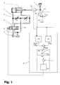
- a foot pedal 1 is shown schematically, which may in particular be the brake pedal or the accelerator pedal of a motor vehicle.
- the pedal is pivotally attached to the motor vehicle about an axis and has a pedal plate on which the driver can exert the pedal force F pedal .
- the pedal 1 can move about the pivot axis, whereby the pedal plate is deflected to the position s pedal .
- the pedal sensation perceived by the driver when the pedal 1 is actuated is determined by the relationship between the pedal travel s pedal and the pedal force F pedal . Since in modern motor vehicles, the controls made by the pedal are usually of active units - such as. B. a brake booster - are executed or supported, the existing connection between pedal force and the function control caused by a purely mechanical pedal is largely lost.
- the pedal 1 is coupled to the piston of a hydraulic cylinder 2 in the device according to the invention, so that a force is exerted on the pedal 1 and the pedal thereof by a corresponding control of the hydraulic cylinder 2 Position can be adjusted.
- the hydraulic cylinder 2 is controlled as described below so that a desired relationship between the pedal travel s pedal and pedal force F pedal arises.
- both the working volume A and the complementary volume K can be pressurized with high pressure or low pressure, it is a double-acting hydraulic cylinder 2.
- the feed lines 3 and 4 to the complementary volume K or working volume A via a hydraulic one Node and a hydraulic throttle 9 and 8, respectively connected to the low pressure reservoir 6.
- a hydraulic one Node and a hydraulic throttle 9 and 8 respectively connected to the low pressure reservoir 6.
- the chokes 8 and 9 are preferably included manually or electrically adjustable, in the latter case it is possible adapt the throttle coefficient to the operating point of the pedal feel simulation.
- FIG. 2 shows a variant of the device described so far, which with a single-acting hydraulic cylinder 2 'works. Furthermore, this variant in contrast to Figure 1, only one throttle 18 is provided, which the supply lines 4 and 3 to work volume A or complementary volume K connects with each other. There is no connection to the low pressure reservoir therefore.
- the throttle 18 can be arranged externally, as shown in FIG. 2, however, it could also be integrated internally into the piston of the hydraulic cylinder 2 ' his.
- the measured force F m and the pedal position s m are processed in a first block 14 according to a first algorithm in order to calculate the pedal force F pedal plus a dynamic force component F dyn from this.
- the dynamic force F dyn is caused by inertial effects of the pedal mechanism. With low dynamics, this can be neglected, and from the kinematics of the pedal mechanism, which is calculated from the pedal travel s m , and the measured force F m can be calculated back to the pedal force F pedal in a good approximation. However, this does not succeed with a high dynamic range, since the inertia force F dyn of the pedal mechanism then increases significantly.
- F dyn is therefore calculated in a second block 15 from the input variables of the pedal acceleration a m and the measured pedal position s m . This can e.g. B. happen with the help of stored characteristics. The determined value of F dyn can then be subtracted from the output of block 14 in order to determine the pedal force F pedal sought.
- the determined pedal force F pedal is used as an input in order to use it to calculate the target position s d of the pedal 1 in accordance with a desired actuation behavior.
- the desired pedal characteristic which in principle can be freely specified, is implemented as a force-position curve.
- the target position s d then represents the reference variable for a downstream electro-hydraulic position control loop.
- the control deviation s d - s m between the target position and the measured pedal position is first calculated.
- a suitable manipulated variable for controlling the servo valve 5 is then calculated according to a control algorithm such as a proportional-integral-differential algorithm and passed on to the latter.
- the hydraulic cylinder 2 is pressurized in such a way that it moves the coupled pedal 1 in the direction of the desired target position s d .
- the described active simulation device can be used with passive pedal feeling simulators be combined.
- a passive pedal feeling simulator understood a device in which a certain pedal feeling with only passive elements to which no energy is supplied from outside, is realized.
- the pedal angle or pedal position is adjusted by an electro-hydraulic servo unit, which is part of a position control loop.
- the reference variable of the control loop is the pedal position s d , which is calculated from the pedal force F pedal and suitable mathematical algorithms. Since the algorithms can be freely selected in their structure and their parameters, different pedal feelings can be represented with the device.
- the pedal force F pedal is determined by a force transducer 11 arranged in the coupling rod between the hydraulic cylinder and the pedal, disruptive dynamic forces being able to be eliminated by calculation by an additional measurement of the pedal acceleration a m .
Landscapes
- Engineering & Computer Science (AREA)
- Transportation (AREA)
- Mechanical Engineering (AREA)
- Physics & Mathematics (AREA)
- Fluid Mechanics (AREA)
- Mechanical Control Devices (AREA)
- Auxiliary Drives, Propulsion Controls, And Safety Devices (AREA)
- Braking Elements And Transmission Devices (AREA)
Priority Applications (3)
| Application Number | Priority Date | Filing Date | Title |
|---|---|---|---|
| DE50206135T DE50206135D1 (de) | 2002-11-05 | 2002-11-05 | Vorrichtung und Verfahren zur Simulation eines Pedalverhaltens |
| EP02102535A EP1418105B1 (fr) | 2002-11-05 | 2002-11-05 | Dispositif et procédé de simulation de la caractéristique d'une pédale |
| US10/701,892 US20040145322A1 (en) | 2002-11-05 | 2003-11-05 | Apparatus and method for simulating a pedal behavior |
Applications Claiming Priority (1)
| Application Number | Priority Date | Filing Date | Title |
|---|---|---|---|
| EP02102535A EP1418105B1 (fr) | 2002-11-05 | 2002-11-05 | Dispositif et procédé de simulation de la caractéristique d'une pédale |
Publications (2)
| Publication Number | Publication Date |
|---|---|
| EP1418105A1 true EP1418105A1 (fr) | 2004-05-12 |
| EP1418105B1 EP1418105B1 (fr) | 2006-03-22 |
Family
ID=32103998
Family Applications (1)
| Application Number | Title | Priority Date | Filing Date |
|---|---|---|---|
| EP02102535A Expired - Lifetime EP1418105B1 (fr) | 2002-11-05 | 2002-11-05 | Dispositif et procédé de simulation de la caractéristique d'une pédale |
Country Status (3)
| Country | Link |
|---|---|
| US (1) | US20040145322A1 (fr) |
| EP (1) | EP1418105B1 (fr) |
| DE (1) | DE50206135D1 (fr) |
Cited By (5)
| Publication number | Priority date | Publication date | Assignee | Title |
|---|---|---|---|---|
| FR2919744A1 (fr) * | 2007-07-31 | 2009-02-06 | Renault Sas | Dispositif de restitution d'efforts pour un stimulateur de conduite. |
| DE102012221146A1 (de) * | 2012-11-20 | 2014-05-22 | Continental Teves Ag & Co. Ohg | Bremsanlage für Kraftfahrzeuge |
| EP2716513A4 (fr) * | 2011-05-23 | 2016-03-30 | Bosch Gmbh Robert | Simulateur de course, maître-cylindre équipé d'un simulateur de course et système de frein utilisant un maître-cylindre |
| DE102016219622B4 (de) | 2016-10-10 | 2019-06-13 | Robert Bosch Gmbh | Verfahren zur Erkennung einer Prellbewegung eines Pedals |
| DE102017212218B4 (de) | 2017-07-17 | 2020-07-09 | Volkswagen Aktiengesellschaft | Simulationssystem zur Anpassung eines Pedalgefühls bei einem Bremssystem |
Families Citing this family (10)
| Publication number | Priority date | Publication date | Assignee | Title |
|---|---|---|---|---|
| KR100951466B1 (ko) * | 2008-12-12 | 2010-04-07 | 한국건설기술연구원 | 중온 아스팔트 첨가제 조성물과 그 첨가제의 제조방법, 그리고 그 제조방법으로 제조된 첨가제를 이용한 중온 아스팔트 혼합물의 생산방법 |
| DE102009026966A1 (de) * | 2008-12-18 | 2010-07-01 | Robert Bosch Gmbh | Betrieb eines Bremskraftverstärkers als Pedalsimulator |
| WO2011019767A1 (fr) * | 2009-08-10 | 2011-02-17 | Hindsight Manufacturing, Llc | Simulateur de pédale |
| CN107310537A (zh) * | 2017-07-22 | 2017-11-03 | 华东交通大学 | 一种差径活塞结构的制动踏板感觉模拟器 |
| DE112020002307T5 (de) | 2019-05-09 | 2022-02-17 | Cts Corporation | Fahrzeugbremspedal mit pedalwiderstandsbaugruppe und kraft-/positionssensor |
| CN116917172A (zh) | 2021-01-13 | 2023-10-20 | Cts公司 | 车辆踏板阻力阻尼组件 |
| CN118076521A (zh) | 2021-10-11 | 2024-05-24 | Cts公司 | 带位置传感器的车辆踏板弹簧阻尼模拟器组件 |
| CN114802156B (zh) * | 2022-04-22 | 2023-04-25 | 江苏恒力制动器制造有限公司 | 考虑驾驶员踏板操作特性的电子液压制动系统及控制方法 |
| US12090980B2 (en) | 2022-09-06 | 2024-09-17 | Cts Corporation | Brake pedal emulator |
| WO2025083588A1 (fr) * | 2023-10-16 | 2025-04-24 | Ka Group Ag | Ensemble pédale à résistance variable |
Citations (7)
| Publication number | Priority date | Publication date | Assignee | Title |
|---|---|---|---|---|
| DE19638102C1 (de) * | 1996-09-18 | 1997-08-21 | Lucas Ind Plc | Betätigungseinheit für eine elektronisch gesteuerte Fahrzeugbremsanlage |
| DE19832036A1 (de) * | 1997-07-17 | 1999-01-28 | Aisin Seiki | Bremssteuerungseinrichtung mit einem Hubsimulator |
| US6050653A (en) * | 1997-01-17 | 2000-04-18 | Jidosha Kiki Co., Ltd | Electrically controlled braking system |
| WO2000068056A1 (fr) | 1999-05-05 | 2000-11-16 | Lucas Industries Plc. | Freinage de secours dans un systeme de freinage electrohydraulique (ehb) |
| US6149247A (en) * | 1997-01-15 | 2000-11-21 | Robert Bosch Gmbh | Hydraulic brake system for a vehicle |
| DE10039670A1 (de) * | 2000-08-14 | 2002-03-07 | Lucas Varity Gmbh | Pedalsimulationsvorrichtung |
| DE10053994A1 (de) * | 2000-09-27 | 2002-04-11 | Continental Teves Ag & Co Ohg | Betätigungswegsimulator für eine Fahrzeugbetätigungseinrichtung |
Family Cites Families (4)
| Publication number | Priority date | Publication date | Assignee | Title |
|---|---|---|---|---|
| DE3427358A1 (de) * | 1984-07-25 | 1986-02-06 | Robert Bosch Gmbh, 7000 Stuttgart | Verfahren zur rueckmeldung von stoerungen in bremsanlagen und nach diesem verfahren arbeitende bremsanlage |
| JPH11513951A (ja) * | 1997-04-16 | 1999-11-30 | シーメンス アクチエンゲゼルシヤフト | 電気的に制御されて操作されるブレーキ装置のための制動値発生器 |
| GB2345322B (en) * | 1998-12-31 | 2002-12-11 | Lucas Ind Plc | Driver warning of braking malfunction in electro-hydraulic (EHB) braking systems |
| US6309031B1 (en) * | 1999-12-14 | 2001-10-30 | Ford Global Technology, Inc. | Vehicle brake system with variable brake pedal feel |
-
2002
- 2002-11-05 EP EP02102535A patent/EP1418105B1/fr not_active Expired - Lifetime
- 2002-11-05 DE DE50206135T patent/DE50206135D1/de not_active Expired - Lifetime
-
2003
- 2003-11-05 US US10/701,892 patent/US20040145322A1/en not_active Abandoned
Patent Citations (7)
| Publication number | Priority date | Publication date | Assignee | Title |
|---|---|---|---|---|
| DE19638102C1 (de) * | 1996-09-18 | 1997-08-21 | Lucas Ind Plc | Betätigungseinheit für eine elektronisch gesteuerte Fahrzeugbremsanlage |
| US6149247A (en) * | 1997-01-15 | 2000-11-21 | Robert Bosch Gmbh | Hydraulic brake system for a vehicle |
| US6050653A (en) * | 1997-01-17 | 2000-04-18 | Jidosha Kiki Co., Ltd | Electrically controlled braking system |
| DE19832036A1 (de) * | 1997-07-17 | 1999-01-28 | Aisin Seiki | Bremssteuerungseinrichtung mit einem Hubsimulator |
| WO2000068056A1 (fr) | 1999-05-05 | 2000-11-16 | Lucas Industries Plc. | Freinage de secours dans un systeme de freinage electrohydraulique (ehb) |
| DE10039670A1 (de) * | 2000-08-14 | 2002-03-07 | Lucas Varity Gmbh | Pedalsimulationsvorrichtung |
| DE10053994A1 (de) * | 2000-09-27 | 2002-04-11 | Continental Teves Ag & Co Ohg | Betätigungswegsimulator für eine Fahrzeugbetätigungseinrichtung |
Cited By (6)
| Publication number | Priority date | Publication date | Assignee | Title |
|---|---|---|---|---|
| FR2919744A1 (fr) * | 2007-07-31 | 2009-02-06 | Renault Sas | Dispositif de restitution d'efforts pour un stimulateur de conduite. |
| EP2020652A3 (fr) * | 2007-07-31 | 2009-07-08 | Renault S.A.S. | Système hybride de commande de frein |
| EP2716513A4 (fr) * | 2011-05-23 | 2016-03-30 | Bosch Gmbh Robert | Simulateur de course, maître-cylindre équipé d'un simulateur de course et système de frein utilisant un maître-cylindre |
| DE102012221146A1 (de) * | 2012-11-20 | 2014-05-22 | Continental Teves Ag & Co. Ohg | Bremsanlage für Kraftfahrzeuge |
| DE102016219622B4 (de) | 2016-10-10 | 2019-06-13 | Robert Bosch Gmbh | Verfahren zur Erkennung einer Prellbewegung eines Pedals |
| DE102017212218B4 (de) | 2017-07-17 | 2020-07-09 | Volkswagen Aktiengesellschaft | Simulationssystem zur Anpassung eines Pedalgefühls bei einem Bremssystem |
Also Published As
| Publication number | Publication date |
|---|---|
| US20040145322A1 (en) | 2004-07-29 |
| DE50206135D1 (de) | 2006-05-11 |
| EP1418105B1 (fr) | 2006-03-22 |
Similar Documents
| Publication | Publication Date | Title |
|---|---|---|
| EP1418105B1 (fr) | Dispositif et procédé de simulation de la caractéristique d'une pédale | |
| EP2379377B1 (fr) | Fonctionnement d'un servofrein en tant que simulateur de pédale, et servofrein configuré de manière correspondante | |
| EP2209678B1 (fr) | Unité de commande de frein | |
| EP2160307B1 (fr) | Simulateur de course de pedale | |
| EP1233891B2 (fr) | Simulateur pour systeme d'actionnement non hydraulique | |
| DE10039670A1 (de) | Pedalsimulationsvorrichtung | |
| EP1220773A1 (fr) | Systeme pour commander des composants de vehicules selon le principe de la conduite par fil | |
| EP1796945B1 (fr) | Procede pour etalonner la caracteristique de courant/d'ouverture d'une soupape hydraulique a commande electrique et a regulation analogique | |
| DE19931865A1 (de) | Schleppfahrzeug für Flugzeuge | |
| DE19537258C2 (de) | Fahrzeugbremsanlage | |
| DE102010035825A1 (de) | Steuerorgansystem und Vorrichtung zur Erzeugung eines virtuellen Echtzeitmodells | |
| DE69426989T2 (de) | Verfahren und system zur regelung einer druckflüssigkeit und dafür verwendbare ventilanordnung | |
| DE19951119A1 (de) | Verfahren und Vorrichtung zur Steuerung einer Fahrzeugs | |
| EP1296865B1 (fr) | Procede et systeme asservi de commande d'un systeme de freinage a regulation electronique | |
| DE19607048A1 (de) | Bremsanlagen für ein motorgetriebenes Kraftfahrzeug und Verfahren zum Steuern dieser Bremsanlage | |
| EP1324902B1 (fr) | Simulateur de course d'actionnement pour une unite d'actionnement de vehicule | |
| WO2011032586A1 (fr) | Procédé de commande d'un système d'actionnement, et système d'actionnement correspondant | |
| DE19834661A1 (de) | Verfahren und Vorrichtung zur Steuerung einer Bremsanlage | |
| EP4688531A1 (fr) | Procédé de génération d'une rétroaction de chaussée pour un conducteur de véhicule à partir d'excitations de chaussée basse fréquence d'un système de direction à commande électrique, et système de direction à commande électrique | |
| DE102018219523A1 (de) | Simulator für Brake-by-Wire-Bremssysteme, Betriebsverfahren und Bremssystem | |
| DE102016219735A1 (de) | Verfahren zur Anpassung einer hinterlegten Druck-Volumen-Kennlinie in einem Bremssystem und Bremssystem | |
| DE10235373B4 (de) | Verfahren zur Prüfung einer hydraulischen Fahrzeugbremsanlage auf ungelöstes Gas in der Bremsflüssigkeit | |
| DE102004019354A1 (de) | Bremsanlage für ein Fahrzeug | |
| DE102019204904B3 (de) | Bremskrafterzeuger und Betriebsverfahren | |
| EP1750112B2 (fr) | Procédé d'application de forces supplémentaires lors de l'exécution d'essais de collision et montage d'essai correspondant |
Legal Events
| Date | Code | Title | Description |
|---|---|---|---|
| PUAI | Public reference made under article 153(3) epc to a published international application that has entered the european phase |
Free format text: ORIGINAL CODE: 0009012 |
|
| AK | Designated contracting states |
Kind code of ref document: A1 Designated state(s): AT BE BG CH CY CZ DE DK EE ES FI FR GB GR IE IT LI LU MC NL PT SE SK TR |
|
| AX | Request for extension of the european patent |
Extension state: AL LT LV MK RO SI |
|
| 17P | Request for examination filed |
Effective date: 20041112 |
|
| 17Q | First examination report despatched |
Effective date: 20041209 |
|
| AKX | Designation fees paid |
Designated state(s): DE FR GB |
|
| RAP1 | Party data changed (applicant data changed or rights of an application transferred) |
Owner name: FORD GLOBAL TECHNOLOGIES, LLC |
|
| GRAP | Despatch of communication of intention to grant a patent |
Free format text: ORIGINAL CODE: EPIDOSNIGR1 |
|
| GRAS | Grant fee paid |
Free format text: ORIGINAL CODE: EPIDOSNIGR3 |
|
| GRAA | (expected) grant |
Free format text: ORIGINAL CODE: 0009210 |
|
| AK | Designated contracting states |
Kind code of ref document: B1 Designated state(s): DE FR GB |
|
| REG | Reference to a national code |
Ref country code: GB Ref legal event code: FG4D Free format text: NOT ENGLISH |
|
| RIN1 | Information on inventor provided before grant (corrected) |
Inventor name: AUGSBURG, KLAUS, PROF. DR. Inventor name: TRUTSCHEL, RALF |
|
| REF | Corresponds to: |
Ref document number: 50206135 Country of ref document: DE Date of ref document: 20060511 Kind code of ref document: P |
|
| RAP2 | Party data changed (patent owner data changed or rights of a patent transferred) |
Owner name: FORD GLOBAL TECHNOLOGIES, LLC. |
|
| GBT | Gb: translation of ep patent filed (gb section 77(6)(a)/1977) |
Effective date: 20060712 |
|
| ET | Fr: translation filed | ||
| PLBE | No opposition filed within time limit |
Free format text: ORIGINAL CODE: 0009261 |
|
| STAA | Information on the status of an ep patent application or granted ep patent |
Free format text: STATUS: NO OPPOSITION FILED WITHIN TIME LIMIT |
|
| 26N | No opposition filed |
Effective date: 20061227 |
|
| PGFP | Annual fee paid to national office [announced via postgrant information from national office to epo] |
Ref country code: GB Payment date: 20101022 Year of fee payment: 9 |
|
| PGFP | Annual fee paid to national office [announced via postgrant information from national office to epo] |
Ref country code: FR Payment date: 20111103 Year of fee payment: 10 |
|
| PGFP | Annual fee paid to national office [announced via postgrant information from national office to epo] |
Ref country code: DE Payment date: 20111130 Year of fee payment: 10 |
|
| GBPC | Gb: european patent ceased through non-payment of renewal fee |
Effective date: 20121105 |
|
| REG | Reference to a national code |
Ref country code: FR Ref legal event code: ST Effective date: 20130731 |
|
| REG | Reference to a national code |
Ref country code: DE Ref legal event code: R119 Ref document number: 50206135 Country of ref document: DE Effective date: 20130601 |
|
| PG25 | Lapsed in a contracting state [announced via postgrant information from national office to epo] |
Ref country code: DE Free format text: LAPSE BECAUSE OF NON-PAYMENT OF DUE FEES Effective date: 20130601 |
|
| PG25 | Lapsed in a contracting state [announced via postgrant information from national office to epo] |
Ref country code: GB Free format text: LAPSE BECAUSE OF NON-PAYMENT OF DUE FEES Effective date: 20121105 Ref country code: FR Free format text: LAPSE BECAUSE OF NON-PAYMENT OF DUE FEES Effective date: 20121130 |