EP1418112B1 - Ensemble de colonne de direction - Google Patents
Ensemble de colonne de direction Download PDFInfo
- Publication number
- EP1418112B1 EP1418112B1 EP03023978A EP03023978A EP1418112B1 EP 1418112 B1 EP1418112 B1 EP 1418112B1 EP 03023978 A EP03023978 A EP 03023978A EP 03023978 A EP03023978 A EP 03023978A EP 1418112 B1 EP1418112 B1 EP 1418112B1
- Authority
- EP
- European Patent Office
- Prior art keywords
- steering column
- column assembly
- clamping
- engagement
- pivot
- Prior art date
- Legal status (The legal status is an assumption and is not a legal conclusion. Google has not performed a legal analysis and makes no representation as to the accuracy of the status listed.)
- Expired - Lifetime
Links
- 230000006641 stabilisation Effects 0.000 claims description 4
- 238000011105 stabilization Methods 0.000 claims description 4
- 230000000694 effects Effects 0.000 claims description 2
- 230000007246 mechanism Effects 0.000 description 15
- 210000003127 knee Anatomy 0.000 description 7
- 230000033001 locomotion Effects 0.000 description 6
- 208000027418 Wounds and injury Diseases 0.000 description 5
- 230000006378 damage Effects 0.000 description 5
- 208000014674 injury Diseases 0.000 description 5
- 210000002414 leg Anatomy 0.000 description 5
- 206010000369 Accident Diseases 0.000 description 2
- 230000000712 assembly Effects 0.000 description 2
- 238000000429 assembly Methods 0.000 description 2
- 238000006073 displacement reaction Methods 0.000 description 2
- 241001295925 Gegenes Species 0.000 description 1
- 206010060820 Joint injury Diseases 0.000 description 1
- 208000016593 Knee injury Diseases 0.000 description 1
- 230000000052 comparative effect Effects 0.000 description 1
- 238000010276 construction Methods 0.000 description 1
- 230000001419 dependent effect Effects 0.000 description 1
- 238000011161 development Methods 0.000 description 1
- 230000018109 developmental process Effects 0.000 description 1
- 230000002349 favourable effect Effects 0.000 description 1
- 231100001261 hazardous Toxicity 0.000 description 1
- 230000000087 stabilizing effect Effects 0.000 description 1
- 239000006228 supernatant Substances 0.000 description 1
Images




Classifications
-
- B—PERFORMING OPERATIONS; TRANSPORTING
- B62—LAND VEHICLES FOR TRAVELLING OTHERWISE THAN ON RAILS
- B62D—MOTOR VEHICLES; TRAILERS
- B62D1/00—Steering controls, i.e. means for initiating a change of direction of the vehicle
- B62D1/02—Steering controls, i.e. means for initiating a change of direction of the vehicle vehicle-mounted
- B62D1/16—Steering columns
- B62D1/18—Steering columns yieldable or adjustable, e.g. tiltable
- B62D1/184—Mechanisms for locking columns at selected positions
Definitions
- the invention relates generally to a steering column assembly for a vehicle according to the preamble of claim 1.
- Such steering assemblies are safety devices and generally serve to reduce injury risks and injuries to drivers.
- mechanical steering column longitudinal and height adjustments usually consist of plate packs which are connected by means of clamping bolts and guided in slots.
- the disk packs usually consist of two different types of disks.
- One type of plate has slots for longitudinal displacement of the steering column. These are attached to the steering column housing.
- the second type of plate has perpendicular slots. These plates are rigidly attached to a base plate, which in turn is bolted to the vehicle. Within the length of the slots, each position of the steering column is possible.
- a clamping device is mounted, the threaded or cam the plate packs braced or braced.
- the plates may also be pivotable strips, such as according to the PCT WO 97/16337 ,
- the clearance below is basically essential for safety reasons, since the legs of the driver are endangered in the event of a frontal impact or similar accidents due to the deformation of the surroundings of this clearance.
- a particular danger is based on the steering column arrangement itself, when this is deformed into the space inside. But even the undeformed steering column assembly itself represents a risk of injury in the case of such accidents.
- Leksverstell Roaden and height adjustment are responsible, on the one hand responsible for a fairly low position of the steering column assembly and on the other hand protrude beyond the contour of the steering column assembly.
- the Lssensverstell listeningen includes a slot guide, which extends linearly in the longitudinal direction of the steering column assembly and engagement means guided therein, wherein the height adjustment means comprise pivot means which engage the engagement means of the LssensverstellISSISSISSISS
- the slot guide on both sides of Steering column assembly includes linearly in the longitudinal direction of the latter extending guide slots, and the engagement means guided therein are formed by a lying only on one side of the steering column assembly engaging part, is provided according to the invention that the engagement part has a matched to the outer contour of the steering column assembly center portion and engagement ends adjacent lie the steering column assembly.
- the pivot means comprise at least one pivot lever which engages with one end on the engagement means of the Lssensverstell tillen and is pivotally connected at its other end to the vehicle, in particular a base plate which is connected to the vehicle.
- the pivoting devices contain a stabilization.
- the stabilization on at least one guide lever which engages with one end of the engagement means of Leksverstell Roaden and is pivotally hinged at its other end to the vehicle, in particular a base plate which is connected to the vehicle, and contains each guide lever and / or if necessary Each swivel lever has a length compensation.
- clamping devices are preferably provided which engage the engagement devices of the longitudinal adjustment devices.
- the clamping means comprise a plurality of clamping plates, which can be actuated via the engagement means of the L Lucassverstell Steinen, since thus a particularly high clamping force can be generated.
- the respective levers are received at their respective ends between the clamping plates, so that when jamming a setting position of the steering column assembly by means of the clamping plates on the engagement means of Leksverstell respondeden both latter and the Pivot lever and possibly guide lever and thus the height adjustment are fixed.
- the clamping devices contain holding devices that are operable with respect to the engagement means for actuating the clamping devices, wherein the holding devices in particular screws, screw threads, nuts, levers and / or cams included.
- the clamping devices include a plurality of clamping plates and at least one clamping piece associated therewith, which is designed such that it has to achieve a clamping effect, an overlap with the clamping plates and possibly pivot levers and / or guide levers. It is preferred if the clamping piece is designed in a slight arc of preferably a few hundredths of a millimeter, so that at the ends or end regions, the largest clamping force is exercised.
- the engagement means with respect to the position of the steering column assembly in the vehicle does not protrude beyond the steering column assembly and in particular above the steering column assembly are guided around this, the engagement means in particular at most around the upper Half of the steering column assembly are guided around.
- the engagement means for actuating the Klemmeinrichnmgen are pivotable.
- the engagement means at most by about 60 °, in particular by about 45 ° and preferably by about 30 °, more preferably by about half of each above statement from a middle position in both Directions that are swiveling.
- the engagement member is formed by a bolt containing offsets, by means of which it is guided around the steering column assembly, the bolt having in particular a circular cross-section.
- the Leksverstell annoyingen and height adjustment devices are on one side or in particular on both sides laterally next to the steering column assembly.
- the slot guide of the longitudinal adjustment devices has at least one guide slot, which is formed in an adjustment plate.
- weight relief devices are arranged so that the weight of the steering column assembly is at least partially compensated.
- the weight relief devices include a coil spring acting between the vehicle and the steering column assembly. Is preferred this is realized in that the clock spring on one hand the pivot means and on the other hand, a base plate is effectively arranged, to attack the pivoting means.
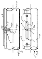
- Fig. 1 and 2 show in cross-section or in a side view of a steering column assembly 1 suspended from a base plate 2, such as a sliding plate.
- the base plate 2 is mounted in guides 3 attached to a body (not shown) of a vehicle (not shown).
- pivotally mounted pivoting lever 4 which are part of pivoting devices 5, which in turn belong to height adjustment devices 6.
- An inventively following the steering contour shaped bolt as an engaging part 7 is space-saving by its shape and represents engagement means 8 of L jossverstell respondeden 9.
- a space 10 for receiving a pyrotechnic adjusting cylinder (not shown) is indicated, by means of which in the event of an accident, the steering column assembly 1 can be moved away from a driver and as in the earlier applications DE 198 44 412.5 and PCT / DE 99/01000 the present applicant is described.
- Denoted by 11 is an impact pad that covers the steering column assembly 1 toward the legs of a driver.
- the steering shaft of the steering column assembly 1 is denoted by 12.
- the steering column assembly 1 also includes a steering column 13. In solid lines, the position of the steering column assembly 1 in an upper position A1 and dash-dotted lines the position of the steering column assembly 1 is shown in a lower position B1.
- both sides of the steering column assembly 1 include a plurality of clamping plates 15 which are arranged laterally on the steering column assembly 1 and between which each pivot lever 4 are received with their respective end portions.
- the Fig. 2 clearly shows a guide slot 16 of a slot guide 17, which is part of the Lssensverstell respondeden 9.
- FIG. 3 3 shows schematically how the bolt 7 of the engagement device 8, instead of turning, as is usual with straight bolts, pivots about 30 ° or 45 ° to 60 ° in order to bring about an actuation of the clamping devices 14.
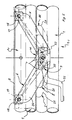
- the Fig. 4 shows in each case schematically the upper position A1 of the steering column assembly 1 from one side and the lower position B 1 of the steering column assembly 1 from the other side, clarifying the function and arrangement of the pivot lever 4.
- the latter are pivotally mounted on bearing blocks 18 by means of bearing pin 19 on the sliding plate or on the Base plate 2 is mounted and clamped at its intersection with the clamping bolt or bolt 7 generally.
- a length compensation 20 in the form of a slot 21 is shown in each pivot lever 4, in which the respective end portion 22a and 22b of the bolt 7 is received.
- the length compensation 20 allows, for example, a linear guide the steering column assembly 1 at a height adjustment instead of a guide along an arc, as it would be the case if the length compensation 20 would not be included, the end portions 22a and 22b in normal fitting holes (not shown) in the corresponding end portions of the pivot lever 4 would be added. The latter is also possible as a design.
- the pin 7 between its two end portions 22a and 22b has a central portion 23 which is guided arcuately around the cross section of the steering column assembly 1 at the top thereof.
- the bolt 7 is thus bent so to speak between its two end portions 22a and 22b.
- sufficient space is created underneath the base plate 2 in the region of the end regions 22a and 22b of the bolt 7 in order to accommodate the longitudinal adjustment devices 9, the height adjustment devices 6 and the clamping devices 14, without creating a specific height for this purpose.
- the bolt 7 or more precisely its center portion 23 lies between the base plate 2 and the steering column assembly 1, ie above the latter relative to the vehicle (not shown).
- the Fig. 5 also shows the upper and lower positions A1 and B1 of the steering column assembly 1 and in addition a clamping piece 24 in the front, a middle and rear horizontal or longitudinal position I, II and III.
- the clamping piece 24 is as long as possible because of the lever ratios and thereby introduced forces. Further, the clamping piece 24 is bent slightly so that it transmits the power especially at the ends (favorable leverage ratios).
- a guide lever 26 is shown, which, like the pivot lever 4 belongs to the height adjustment devices 6 and serves to stabilize the latter.
- a plurality of guide levers 26 may be provided on each side of the steering column assembly 1, respectively and be alternately engaged in the respective end regions with the clamping plates 15 and the corresponding end portions of the pivot lever 4 in the clamping devices 14.
- the guide lever 26 in the end regions, which are coupled to the bolt 7, each have a length compensation 20, whereby the movement path in the height adjustment can be made more free.
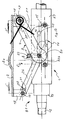
- the Fig. 6 schematically shows a Lcnkklalenan für a steering column assembly 1 in its / its uppermost position A1, positioned parallel to a base plate 2 to illustrate a further possible embodiment of the safety device according to the invention.
- two steering-side bearing blocks 18 and two bearing blocks 18 are mounted on the motor side at the four corners.
- pivot arms or levers 4 are bolted at one end by means of bearing pin 19.
- the pivot arms 4 terminate at the other end with the largest possible circular area 27, in the middle of the end portions 22a, 22b of the bolt 7 of the engagement means 8 of the Leksverstell Roaden 9 are inserted.
- This pivot arm 4 can pivot about the bearing pin 19.
- the pivot arms or levers 4 have only fixed holes for pivoting and no length compensation 20, neither on the bearing blocks 18, nor the bolt 7.
- a package of pivot levers 4 respectively be provided in parallel to increase the stability.
- a package of support or guide levers 26 are again gebolzt by means of bearing pin 19 at one end.
- the other end also ends with a large circular area 28, through the center of which the end areas 22a, 22b of the bolt 7 of the engagement devices 8 of the longitudinal adjustment devices 9 are also pushed through.
- the support arm or lever 26 stabilizes theriosnein- or adjustment mechanism or devices 6 to a triangle and has in the case shown at its bearing block end a relatively short length compensation 20, which could also be provided at the other end or at both ends, or alternatively or additionally could be provided in one end or in both ends of the pivot lever 4.
- the Fig. 6 and 7 show the length compensation 20 at the end of the guide lever 26 on the side of the bearing block 18th Die
- the Fig. 12 shows the length compensation 20 at the end of the guide lever 26 on the side of the clamping devices 14 as a further merely exemplary embodiment variant.
- the pivot lever 4, guide or support lever 26 and clamping plates or plates 15 are mutually mounted on both sides in the number until the necessary clamping strength is achieved in particular in the event of a crash.
- the Fig. 7 shows the erfindungsgenläße kinematics at the lowest position B 1 of the steering column assembly 1 in position away from the driver.
- Fig. 6 and 7 In the two representations of Fig. 6 and 7 is clearly a bulge 2a shown in the base plate 2, which bulge 2a for receiving the middle portion 23 of the bolt 7 is used to build as high as possible and thereby as much foot space in the vehicle (not shown) below the steering column assembly 1 despite the whole Obtain adjustment mechanisms or devices.
- the Fig. 8 shows on average "B" the Fig. 6 the section through the clamping plates 15 of the clamping devices 14 in its center. Shown are also the technically known clamping cams or rollers 8a, which are part of the clamping devices 14 and serve their function.
- the bolt 7 is space-saving cranked, as already described and explained above, and received with its center portion 23 in the local bulge or bulge 27 in the base plate, so that by the action of both structural designs (bent pin and bulge to its inclusion) extra space is created in comparison with the straight-line clamping axles which are common in practice today and are located below the steering column assembly 1.
- the Fig. 9 shows a section "A" in the Fig. 6 through the steering column assembly 1 and its housing 29.
- Die Fig. 10 shows on average "C” in the Fig. 7 the adjustable steering or steering column assembly 1 in the lowest position B1, cut by the steering-side bearing block 18;
- the Fig. 11 shows the section "D” by the motor-side bracket 18 according to of the Fig. 7 ,
- the Fig. 13 shows as additional weight relief means 30 a space-saving coil spring 31 which is mounted parallel to the pivot arm or lever 4.
- a significant advantage of the invention is that the mechanism never protrudes above the steering assembly and thus no knee are injured in the crash and also results in more knee room. This is achieved by up and down with the height adjustment of the steering column assembly 1 swivel arm or lever 4.
- the cranked clamping bolt 7 and the space-saving designed coil spring 31 contribute to this.
- the invention provides, in particular, a steering column arrangement with a steering column adjustment mechanism which is located laterally next to the steering column and does not protrude spatially above or below, in any adjustment position. This preferably applies to all positions of the steering column.
- the mechanism preferably takes so little space that even space for an impact pad is available.
- the adjusting mechanism moves with the steering column housing.
- the mechanism for adjusting the steering thus particularly crash-critical or protruding parts are to be avoided in the direction of the knees of a driver down.
- the mechanism is on one side or in particular on both sides laterally next to the steering column.
- a clamping piece can additionally be provided and designed such that it reaches a sufficient overlap and thus clamping of the clamping plates and pivot lever.
- This clamping piece can be designed in a slight arc of preferably a few hundredths of a millimeter in such a way that it reaches the greatest clamping force at the respective ends.
- a clamping bolt in the mold is guided around the steering column assembly such that it requires little more space than its vertical thickness dimension.
- the clamping bolt may be shaped such that the clamping mechanism on the thickness dimension of the clamping bolt out no or little extra space needed, at best, for pivoting the clamping bolt in order to operate the clamping devices. So that the clamping bolt is so rotatable and thus pivotable for opening and clamping the steering adjustment, it can be achieved that there is still the smallest possible space requirement.
- the cranked pin then performs a pivoting movement for clamping and in particular moves the clamping mechanisms provided on both sides, for example by means of cams or threads. It is also preferred if the clamping bolt has a rounded shape.
- the steering or steering column assembly according to the invention with a safety device for a vehicle is such that a steering column height and -lijnsverstellmechanik is contained in a compact design, regardless of the adjustment position has no protruding parts, which is optimal for space and knee impact injuries in an accident.
- the pivot arms of the height adjustment devices used in this case are preferably hinged to a base plate which is connected to the body of the vehicle.
- the clamping devices can also be provided that the guide arms end at the other end as a clamping plate to the Verspannbolzen.
- the steering column assembly can be pivoted up and down in a circle segment shape on this swivel arm / these swivel arms.
- adjusting plates can be attached with longitudinal slots on the steering assembly.
- the shape and attachment of the adjustment plates may be such that each position of the adjustment, in particular an upper, is possible.
- These guide arms or levers may pivot up and down with the steering assembly and / or be supported at the other end as well as the pivot arms or levers in the center of the clamp bolt.
- the guide arms or levers will follow the pivot arms or levers and preferably have a slot as a length compensation at one end or at both ends.
- the clamping plates or L jossverstellplatten, pivot arms and guide arms are nested in particular packet by packet.
- the space required in the direction of the instruments is not more than the thickness of the bolt or clamping bolt 7.
- Terminal strips in the form of the pivot lever 4 and the clamping plates 15 are located in any position laterally from the steering. They move with the steering column assembly 1. This gives more room for the knees of a driver. There is no knee-destroying mechanics in a crash. Further, the space obtained by the invention for attaching additional cushions 11 extends to protect the knees in a crash. Thus, in the future, possibly legal safety requirements for crashes can be met.
- the present invention provides a steering column assembly with a safety device and with a longitudinal and vertical adjustment mechanism of a steering column or steering column arrangement, which safety device is designed in such a way and is carried along with the movement that it hardly needs any additional space in the height dimension.
- the clamping bolt or generally the engagement means pivots upon actuation and move the pivot lever for height adjustment with the steering column assembly up and down.
Landscapes
- Engineering & Computer Science (AREA)
- Chemical & Material Sciences (AREA)
- Combustion & Propulsion (AREA)
- Transportation (AREA)
- Mechanical Engineering (AREA)
- Steering Controls (AREA)
- Automobile Manufacture Line, Endless Track Vehicle, Trailer (AREA)
- Electrochromic Elements, Electrophoresis, Or Variable Reflection Or Absorption Elements (AREA)
Claims (23)
- Agencement de colonne de direction (1), comportant des dispositifs de réglage en longueur (9) et des dispositifs de réglage en hauteur (6) pour celui-ci,
les dispositifs de réglage en longueur (9) contenant un guidage à fente (17), qui s'étend de façon linéaire dans la direction longitudinale de l'agencement de colonne de direction (1), et des dispositifs d'engagement (8) guidés dans celui-ci,
les dispositifs de réglage en hauteur (6) contenant des dispositifs de pivotement (5) qui attaquent les dispositifs d'engagement (8) des dispositifs de réglage en longueur (9), et
le guidage à fente (17) contenant de chaque côté de l'agencement de colonne de direction (1) des fentes de guidage (16) s'étendant linéairement dans la direction longitudinale de celui-ci, et les dispositifs d'engagement (8) guidés dans celles-ci étant formés par une pièce d'engagement (7) située seulement sur un côté de l'agencement de colonne de direction (1),
caractérisé en ce que
la pièce d'engagement (7) présente un tronçon central (23) adapté au contour extérieur de l'agencement de colonne de direction (1) et des extrémités d'engagement (22a, 22b) qui sont situées à côté de l'agencement de colonne de direction (1). - Agencement de colonne de direction (1) selon la revendication 1, caractérisé en ce que les dispositifs de pivotement (5) contiennent au moins un levier pivotant (4) qui attaquent par une extrémité les dispositifs d'engagement (8) des dispositifs de réglage en longueur (9) et qui, par son autre extrémité, est articulé de manière pivotante sur le véhicule, en particulier sur une plaque de base (2) qui est reliée au véhicule.
- Agencement de colonne de direction (1) selon la revendication 1 ou 2, caractérisé en ce que les dispositifs de pivotement (5) contiennent une stabilisation.
- Agencement de colonne de direction (1) selon la revendication 3, caractérisé en ce que la stabilisation présente au moins un levier de guidage (26) qui attaque par une extrémité les dispositifs d'engagement (8) des dispositifs de réglage en longueur (9) et qui, par son autre extrémité, est articulé de manière pivotante sur le véhicule, en particulier sur une plaque de base (2) qui est reliée au véhicule, et en ce que chaque levier de guidage (26) et/ou, le cas échéant, chaque levier pivotant (4) contient une compensation de longueur (20).
- Agencement de colonne de direction (1) selon l'une quelconque des revendications précédentes, caractérisé en ce que pour fixer une position de réglage de l'agencement de colonne de direction (1), il est prévu des dispositifs de serrage (14) qui attaquent les dispositifs d'engagement (8) des dispositifs de réglage en longueur (9).
- Agencement de colonne de direction (1) selon la revendication 5, caractérisé en ce que les dispositifs de serrage (14) contiennent une multitude de plaques de serrage (15) qui peuvent être actionnées via les dispositifs d'engagement (8) des dispositifs de réglage en longueur (9).
- Agencement de colonne de direction (1) selon les revendications 2 et 6 ou 2, 4 et 6, caractérisé en ce qu'il est prévu une multitude de leviers pivotants (4) et/ou une multitude de leviers de guidage (26), respectivement, et en ce qu'entre les plaques de serrage (16), des leviers pivotants (4) et, le cas échéant, des leviers de guidage (26) sont reçus avec leurs extrémités correspondantes, de telle sorte qu'en cas de serrage d'une position de réglage de l'agencement de colonne de direction (1) au moyen des plaques de serrage (16) via les dispositifs d'engagement (8) des dispositifs de réglage en longueur (9), tant ces derniers que les leviers pivotants (4) et, le cas échéant, les leviers de guidage (26) et ainsi les dispositifs de réglage en hauteur (6) sont fixés.
- Agencement de colonne de direction (1) selon l'une des revendications 5 à 7, caractérisé en ce que les dispositifs de serrage (14) contiennent des dispositifs de retenue qui peuvent être actionnés vis-à-vis des dispositifs d'engagement (8) pour actionner les dispositifs de serrage (14).
- Agencement de colonne de direction (1) selon la revendication 8, caractérisé en ce que les dispositifs de retenue contiennent des vis, des pas de vis, des écrous, des leviers et/ou des cames.
- Agencement de colonne de direction (1) selon l'une des revendications 5 à 9, caractérisé en ce que les dispositifs de serrage (14) contiennent une multitude de plaques de serrage (15) et au moins une pièce de serrage (24) associée à celles-ci, qui est réalisée de telle sorte que pour atteindre un effet de serrage, elle présente un recouvrement avec les plaques de serrage (15) ainsi que, le cas échéant, avec les leviers pivotants (4) et/ou les leviers de guidage (26).
- Agencement de colonne de direction (1) selon la revendication 10, caractérisé en ce que la pièce de serrage (24) est réalisée en un léger arc de préférence de quelques centièmes de millimètres, de telle sorte que la plus grande force de serrage peut être exercée aux extrémités ou dans les zones d'extrémité.
- Agencement de colonne de direction (1) selon l'une quelconque des revendications précédentes, caractérisé en ce que par rapport à la position de l'agencement de colonne de direction (1) dans le véhicule, les dispositifs d'engagement (8) ne font pas saillie vers le bas au-delà de l'agencement de colonne de direction (1) et sont en particulier guidés au-dessus de l'agencement de colonne de direction (1) autour de celui-ci.
- Agencement de colonne de direction (1) selon la revendication 12, caractérisé en ce que les dispositifs d'engagement (8) sont guidés au maximum autour de la moitié supérieure de l'agencement de colonne de direction (1).
- Agencement de colonne de direction (1) selon la revendication 12 ou 13, en liaison avec l'une des revendications 5 à 11, caractérisé en ce que les dispositifs d'engagement (8) peuvent pivoter pour actionner les dispositifs de serrage (14).
- Agencement de colonne de direction (1) selon la revendication 14, caractérisé en ce que les dispositifs d'engagement (8) sont pivotables au maximum d'environ 60°, en particulier d'environ 45° et de préférence d'environ 30°, de manière particulièrement préférée d'environ la moitié de chaque valeur ci-dessus depuis une position médiane dans les deux directions.
- Agencement de colonne de direction (1) selon l'une quelconque des revendications précédentes, caractérisé en ce que la pièce d'engagement est formée par un boulon (7) qui contient des parties coudées au moyen desquelles il est guidé autour de l'agencement de colonne de direction (1).
- Agencement de colonne de direction (1) selon la revendication 16, caractérisé en ce que le boulon (7) a une section transversale circulaire.
- Agencement de colonne de direction (1) selon l'une quelconque des revendications précédentes, caractérisé en ce que lors d'un réglage en hauteur de l'agencement de colonne de direction (1), les dispositifs de réglage en longueur (9) se déplacent conjointement.
- Agencement de colonne de direction (1) selon l'une quelconque des revendications précédentes, caractérisé en ce que les dispositifs de réglage en longueur (9) et les dispositifs de réglage en hauteur (6) se trouvent latéralement à côté de l'agencement de colonne de direction (1), sur un côté ou en particulier sur deux côtés.
- Agencement de colonne de direction (1) selon l'une quelconque des revendications précédentes, caractérisé en ce que le guidage à fente (17) des dispositifs de réglage en longueur (9) présente au moins une fente de guidage (16) qui est réalisée dans une plaque de réglage.
- Agencement de colonne de direction (1) selon l'une quelconque des revendications précédentes, caractérisé en ce que des dispositifs de décharge de poids (30) sont agencés de telle sorte que le poids de l'agencement de colonne de direction (1) est compensé au moins partiellement.
- Agencement de colonne de direction (1) selon la revendication 21, caractérisé en ce que les dispositifs de décharge de poids (30) contiennent un ressort spiral (31) qui agit entre le véhicule et l'agencement de colonne de direction (1).
- Agencement de colonne de direction (1) selon la revendication 22, caractérisé en ce que le ressort spiral (31) est agencé de manière opérative d'une part sur les dispositifs de pivotement (5) et d'autre part sur une plaque de base (2) qui est attaquée par les dispositifs de pivotement (5).
Applications Claiming Priority (5)
| Application Number | Priority Date | Filing Date | Title |
|---|---|---|---|
| DE1001216 | 2001-02-06 | ||
| DE20101928 | 2001-02-06 | ||
| DE20101928U | 2001-02-06 | ||
| DE0101216 | 2001-03-30 | ||
| EP01985801A EP1360102B1 (fr) | 2001-02-06 | 2001-12-20 | Colonne de direction pour vehicule |
Related Parent Applications (2)
| Application Number | Title | Priority Date | Filing Date |
|---|---|---|---|
| EP01985801A Division EP1360102B1 (fr) | 2001-02-06 | 2001-12-20 | Colonne de direction pour vehicule |
| EP01985801.8 Division | 2001-12-20 |
Publications (3)
| Publication Number | Publication Date |
|---|---|
| EP1418112A2 EP1418112A2 (fr) | 2004-05-12 |
| EP1418112A3 EP1418112A3 (fr) | 2004-05-19 |
| EP1418112B1 true EP1418112B1 (fr) | 2009-02-11 |
Family
ID=25750282
Family Applications (2)
| Application Number | Title | Priority Date | Filing Date |
|---|---|---|---|
| EP03023978A Expired - Lifetime EP1418112B1 (fr) | 2001-02-06 | 2001-12-20 | Ensemble de colonne de direction |
| EP01985801A Expired - Lifetime EP1360102B1 (fr) | 2001-02-06 | 2001-12-20 | Colonne de direction pour vehicule |
Family Applications After (1)
| Application Number | Title | Priority Date | Filing Date |
|---|---|---|---|
| EP01985801A Expired - Lifetime EP1360102B1 (fr) | 2001-02-06 | 2001-12-20 | Colonne de direction pour vehicule |
Country Status (5)
| Country | Link |
|---|---|
| EP (2) | EP1418112B1 (fr) |
| AT (1) | ATE457916T1 (fr) |
| DE (2) | DE50114710D1 (fr) |
| ES (1) | ES2324773T3 (fr) |
| WO (1) | WO2002062645A1 (fr) |
Family Cites Families (7)
| Publication number | Priority date | Publication date | Assignee | Title |
|---|---|---|---|---|
| FR2456652A1 (fr) * | 1979-05-16 | 1980-12-12 | Renault Vehicules Ind | Colonne de direction orientable pour un vehicule routier |
| GB2092967A (en) * | 1981-02-13 | 1982-08-25 | Ford Motor Co | Steering column assembly |
| FR2696145B1 (fr) * | 1992-09-28 | 1994-12-30 | Ecia Equip Composants Ind Auto | Ensemble de colonne de direction réglable en position pour véhicule automobile. |
| GB2306629A (en) * | 1995-10-28 | 1997-05-07 | Nastech Europ Ltd | Adjustable vehicle steering column assembly |
| US6095012A (en) * | 1996-04-18 | 2000-08-01 | Etablissement Supervis | Steering column for a motor vehicle |
| FR2761036B1 (fr) * | 1997-03-19 | 1999-06-04 | Ecia Equip Composants Ind Auto | Ensemble de colonne de direction reglable en position, notamment pour vehicule automobile |
| FR2775945B1 (fr) * | 1998-03-11 | 2000-06-02 | Ecia Equip Composants Ind Auto | Ensemble de colonne de direction reglable en position, par exemple pour vehicule automobile |
-
2001
- 2001-12-20 DE DE50114710T patent/DE50114710D1/de not_active Expired - Lifetime
- 2001-12-20 EP EP03023978A patent/EP1418112B1/fr not_active Expired - Lifetime
- 2001-12-20 WO PCT/DE2001/004873 patent/WO2002062645A1/fr not_active Ceased
- 2001-12-20 DE DE50115355T patent/DE50115355D1/de not_active Expired - Lifetime
- 2001-12-20 AT AT01985801T patent/ATE457916T1/de not_active IP Right Cessation
- 2001-12-20 EP EP01985801A patent/EP1360102B1/fr not_active Expired - Lifetime
- 2001-12-20 ES ES03023978T patent/ES2324773T3/es not_active Expired - Lifetime
Also Published As
| Publication number | Publication date |
|---|---|
| WO2002062645A1 (fr) | 2002-08-15 |
| ES2324773T3 (es) | 2009-08-14 |
| DE50114710D1 (de) | 2009-03-26 |
| ATE457916T1 (de) | 2010-03-15 |
| EP1360102A1 (fr) | 2003-11-12 |
| EP1418112A3 (fr) | 2004-05-19 |
| DE50115355D1 (de) | 2010-04-01 |
| EP1418112A2 (fr) | 2004-05-12 |
| EP1360102B1 (fr) | 2010-02-17 |
Similar Documents
| Publication | Publication Date | Title |
|---|---|---|
| DE102007007101B4 (de) | Hebevorrichtung | |
| DE4342400C2 (de) | Überrollbügeleinrichtung | |
| EP1318737B1 (fr) | Systeme d'entrainement pour meuble, se presentant sous la forme d'un double dispositif d'entrainement | |
| DE60206436T2 (de) | Lenkeinrichtung | |
| EP0724540B1 (fr) | Table elevatrice a systeme de levage du type en ciseaux | |
| EP2251583B1 (fr) | Support, notamment pour caméra | |
| DE10243497B4 (de) | Vorrichtung zum Schutz von Personen bei einem Frontalaufprall auf ein Kraftfahrzeug | |
| EP2611673B1 (fr) | Colonne de direction pour un véhicule automobile | |
| DE69303138T2 (de) | Einstellbare Lenksäuleneinheit für ein Kraftfahrzeug | |
| EP1941815A2 (fr) | Dispositif de direction couplée au mouvement pour une partie de siège, en particulier d'une chaise | |
| DE102008054363A1 (de) | Lenksäulenanordnung | |
| DE102016124696B4 (de) | Fahrzeugkabine oder Fahrzeugsitz mit Höhenverstelleinrichtung | |
| DE69207218T2 (de) | Lenksäule | |
| EP3854263B1 (fr) | Accoudoir, en particulier pour une chaise de bureau | |
| EP0611258B1 (fr) | Machine d'impression au tampon | |
| DE60304403T2 (de) | Scherenhubvorrichtung | |
| EP1418112B1 (fr) | Ensemble de colonne de direction | |
| DE10311533B3 (de) | Vorrichtung zum Schutz von Personen bei einem Frontalaufprall auf ein Kraftfahrzeug | |
| EP1608539A1 (fr) | Dispositif pour proteger des personnes lors d'un choc frontal avec un vehicule | |
| EP0592714A1 (fr) | Dispositif pour amortir les chocs | |
| EP3799588B1 (fr) | Support d'attelage pour un attelage à tampon central d'un véhicule ferroviaire | |
| DE102023120222A1 (de) | Wadenstütze für einen Fahrzeugsitz und ein Fahrzeugsitz umfassend eine Wadenstütze | |
| DE69102024T2 (de) | Kraftdämpfende und zusammenschiebbare Lenksäulehalter. | |
| DE10116523C1 (de) | Sicherheitseinrichtung | |
| WO2005005209A1 (fr) | Dispositif servant a proteger des personnes en cas de choc frontal sur un vehicule automobile |
Legal Events
| Date | Code | Title | Description |
|---|---|---|---|
| PUAI | Public reference made under article 153(3) epc to a published international application that has entered the european phase |
Free format text: ORIGINAL CODE: 0009012 |
|
| PUAL | Search report despatched |
Free format text: ORIGINAL CODE: 0009013 |
|
| AC | Divisional application: reference to earlier application |
Ref document number: 1360102 Country of ref document: EP Kind code of ref document: P |
|
| AK | Designated contracting states |
Kind code of ref document: A2 Designated state(s): AT BE CH CY DE DK ES FI FR GB GR IE IT LI LU MC NL PT SE TR |
|
| AX | Request for extension of the european patent |
Extension state: AL LT LV MK |
|
| AK | Designated contracting states |
Kind code of ref document: A3 Designated state(s): AT BE CH CY DE DK ES FI FR GB GR IE IT LI LU MC NL PT SE TR |
|
| AX | Request for extension of the european patent |
Extension state: AL LT LV MK |
|
| 17P | Request for examination filed |
Effective date: 20041119 |
|
| AKX | Designation fees paid |
Designated state(s): DE ES FR GB IT |
|
| GRAP | Despatch of communication of intention to grant a patent |
Free format text: ORIGINAL CODE: EPIDOSNIGR1 |
|
| RTI1 | Title (correction) |
Free format text: STEERING COLUMN ASSEMBLY |
|
| GRAS | Grant fee paid |
Free format text: ORIGINAL CODE: EPIDOSNIGR3 |
|
| GRAA | (expected) grant |
Free format text: ORIGINAL CODE: 0009210 |
|
| AC | Divisional application: reference to earlier application |
Ref document number: 1360102 Country of ref document: EP Kind code of ref document: P |
|
| AK | Designated contracting states |
Kind code of ref document: B1 Designated state(s): DE ES FR GB IT |
|
| REG | Reference to a national code |
Ref country code: GB Ref legal event code: FG4D Free format text: NOT ENGLISH |
|
| REF | Corresponds to: |
Ref document number: 50114710 Country of ref document: DE Date of ref document: 20090326 Kind code of ref document: P |
|
| REG | Reference to a national code |
Ref country code: ES Ref legal event code: FG2A Ref document number: 2324773 Country of ref document: ES Kind code of ref document: T3 |
|
| PLBE | No opposition filed within time limit |
Free format text: ORIGINAL CODE: 0009261 |
|
| STAA | Information on the status of an ep patent application or granted ep patent |
Free format text: STATUS: NO OPPOSITION FILED WITHIN TIME LIMIT |
|
| 26N | No opposition filed |
Effective date: 20091112 |
|
| REG | Reference to a national code |
Ref country code: FR Ref legal event code: PLFP Year of fee payment: 15 |
|
| PGFP | Annual fee paid to national office [announced via postgrant information from national office to epo] |
Ref country code: ES Payment date: 20160523 Year of fee payment: 15 |
|
| PGFP | Annual fee paid to national office [announced via postgrant information from national office to epo] |
Ref country code: IT Payment date: 20160530 Year of fee payment: 15 |
|
| REG | Reference to a national code |
Ref country code: FR Ref legal event code: PLFP Year of fee payment: 16 |
|
| PGFP | Annual fee paid to national office [announced via postgrant information from national office to epo] |
Ref country code: GB Payment date: 20170626 Year of fee payment: 16 Ref country code: FR Payment date: 20170621 Year of fee payment: 16 |
|
| PG25 | Lapsed in a contracting state [announced via postgrant information from national office to epo] |
Ref country code: IT Free format text: LAPSE BECAUSE OF NON-PAYMENT OF DUE FEES Effective date: 20161220 |
|
| PGFP | Annual fee paid to national office [announced via postgrant information from national office to epo] |
Ref country code: DE Payment date: 20180220 Year of fee payment: 17 |
|
| PG25 | Lapsed in a contracting state [announced via postgrant information from national office to epo] |
Ref country code: ES Free format text: LAPSE BECAUSE OF NON-PAYMENT OF DUE FEES Effective date: 20161221 |
|
| GBPC | Gb: european patent ceased through non-payment of renewal fee |
Effective date: 20171220 |
|
| REG | Reference to a national code |
Ref country code: FR Ref legal event code: ST Effective date: 20180831 |
|
| PG25 | Lapsed in a contracting state [announced via postgrant information from national office to epo] |
Ref country code: FR Free format text: LAPSE BECAUSE OF NON-PAYMENT OF DUE FEES Effective date: 20180102 |
|
| REG | Reference to a national code |
Ref country code: ES Ref legal event code: FD2A Effective date: 20181116 |
|
| PG25 | Lapsed in a contracting state [announced via postgrant information from national office to epo] |
Ref country code: GB Free format text: LAPSE BECAUSE OF NON-PAYMENT OF DUE FEES Effective date: 20171220 |
|
| REG | Reference to a national code |
Ref country code: DE Ref legal event code: R119 Ref document number: 50114710 Country of ref document: DE |
|
| PG25 | Lapsed in a contracting state [announced via postgrant information from national office to epo] |
Ref country code: DE Free format text: LAPSE BECAUSE OF NON-PAYMENT OF DUE FEES Effective date: 20190702 |