EP1418277A1 - Procédé de construction d'un mur de soutènement - Google Patents
Procédé de construction d'un mur de soutènement Download PDFInfo
- Publication number
- EP1418277A1 EP1418277A1 EP03078471A EP03078471A EP1418277A1 EP 1418277 A1 EP1418277 A1 EP 1418277A1 EP 03078471 A EP03078471 A EP 03078471A EP 03078471 A EP03078471 A EP 03078471A EP 1418277 A1 EP1418277 A1 EP 1418277A1
- Authority
- EP
- European Patent Office
- Prior art keywords
- piles
- pile
- primary
- retaining wall
- array
- Prior art date
- Legal status (The legal status is an assumption and is not a legal conclusion. Google has not performed a legal analysis and makes no representation as to the accuracy of the status listed.)
- Withdrawn
Links
- 238000000034 method Methods 0.000 title claims abstract description 27
- 208000014617 hemorrhoid Diseases 0.000 claims abstract description 68
- 239000000203 mixture Substances 0.000 claims abstract description 10
- 230000003014 reinforcing effect Effects 0.000 claims description 20
- 239000011230 binding agent Substances 0.000 claims description 18
- 239000002689 soil Substances 0.000 claims description 15
- 238000005553 drilling Methods 0.000 claims description 7
- 238000002347 injection Methods 0.000 claims description 6
- 239000007924 injection Substances 0.000 claims description 6
- 230000000087 stabilizing effect Effects 0.000 claims description 6
- 230000002787 reinforcement Effects 0.000 description 9
- 238000010276 construction Methods 0.000 description 6
- 239000000463 material Substances 0.000 description 2
- 230000005540 biological transmission Effects 0.000 description 1
- 230000006835 compression Effects 0.000 description 1
- 238000007906 compression Methods 0.000 description 1
Images



Classifications
-
- E—FIXED CONSTRUCTIONS
- E02—HYDRAULIC ENGINEERING; FOUNDATIONS; SOIL SHIFTING
- E02D—FOUNDATIONS; EXCAVATIONS; EMBANKMENTS; UNDERGROUND OR UNDERWATER STRUCTURES
- E02D5/00—Bulkheads, piles, or other structural elements specially adapted to foundation engineering
- E02D5/20—Bulkheads or similar walls made of prefabricated parts and concrete, including reinforced concrete, in situ
Definitions
- the invention relates to a method for constructing a retaining wall, wherein a pile-shaped space is bored in each case in the ground and filled with a curing mixture in order to obtain an array of primary piles at a mutual pitch distance, whereafter at least one secondary pile-shaped space is bored in each case in the ground between each pair of adjacent primary piles and filled with a curing mixture in order to obtain a secondary array of piles, wherein the pitch distance between the primary piles is sealed by at least one secondary pile.
- Bored piles are often used for the construction of temporary earth-retaining walls, such as a sheet piling for a construction site.
- Such techniques are well-known.
- a construction is built up of a series of primary piles, which are for instance formed by boring a pile-shaped space wherein the soil is replaced by concrete. Between each pair of primary piles is then bored a secondary pile-shaped space, which is filled with concrete and in which a reinforcing profile is generally placed.
- the distance between the primary piles is smaller than the diameter of the secondary pile, so that a part of the primary piles is removed by the drilling during boring of the secondary pile-shaped spaces.
- An anchor can subsequently be arranged which runs to the right or left of the reinforcement and therefore not through the middle of the secondary pile.
- Such a technique has the drawback that the asymmetrically arranged anchors do not result in an ideal distribution of the anchor forces.
- a further drawback of this technique is that the primary piles are embodied in concrete, which involves a great deal of soil removal.
- the invention has for its object a method for constructing a retaining wall with bored piles, wherein the reinforcements and the stabilizing members, such as for instance anchors, can be better arranged.
- the method according to the invention is distinguished for this purpose in that a reinforcing profile is placed in at least a number of the array of primary piles, and that at least a number of the secondary piles is provided with stabilizing members, such as an anchor or a strut, this such that the forces exerted transversely of the secondary piles are transmitted to the reinforcing profiles.
- the reinforcement in the primary pile and the anchor in the secondary pile By arranging the reinforcement in the primary pile and the anchor in the secondary pile, the presence of a reinforcement in the same pile is not a problem and a better distribution of the anchor force is obtained. Since the distance between the centres of two adjacent primary piles is smaller than the diameter of the primary pile plus the diameter of the secondary pile multiplied by the number of secondary piles placed between two adjacent primary piles, the forces exerted on the secondary pile by the anchor can be transmitted to the primary pile, and more particularly to the reinforcement present therein. It will be evident that the dimensions and the strength of the piles, as well as the dimensions and strength of the reinforcement, must be such that these forces are adequately transmitted to the reinforcement.
- the primary and secondary piles can be manufactured as desired by for instance on-site mixing or by removing the soil from the bored pile-shaped spaces and filling these spaces with concrete.
- the invention further has for its object to limit soil removal and the costs associated therewith.
- the soil is mixed on-site for this purpose with a binder at the position of the pile-shaped space for the primary pile. This is currently an economically advantageous technique for obtaining the primary piles.
- the applicability of this technique and the choice of binder depends on, among other factors, the nature of the soil in which the retaining wall must be arranged and on the desired strength of the retaining wall.
- the secondary pile-shaped space is filled with concrete.
- Concrete provides the necessary strength to the construction and is an advantageous choice for the purpose of arranging the anchors or struts in the secondary piles.
- At least one yoke is arranged against the periphery formed by the primary and secondary piles, on which yoke the stabilizing members engage.
- the array of secondary piles is formed such that the secondary piles contact an outer periphery which substantially coincides with the outside of reinforcing profiles of the primary piles, and that this side of the reinforcing profiles is exposed, whereafter a yoke is placed against this outer periphery formed by the secondary piles and reinforcing profiles. In this manner a good transfer of the forces from the anchor to the reinforcement is obtained.
- the invention also relates to a method for at least partly demolishing a retaining wall manufactured according to one of the above described methods, wherein the reinforcing profiles of the primary piles are recovered.
- the reinforcing profiles are arranged in the piles mixed on-site, they can be removed from these piles in simple manner, whereafter they can for instance be re-used in a retaining wall to be constructed at a later stage.
- the costs of the relatively expensive reinforcements are thus saved, and no unnecessary, recyclable components are left on site.
- the invention also relates to a retaining wall obtained according to any of the above described variants of the method according to the invention.
- the secondary pile has a diameter which is smaller than or equal to that of the primary pile.
- the centre lines of the array of secondary piles lie in a plane which is at a distance from the centre lines of the primary piles, this such that the primary and secondary piles adjoin the same outer plane.
- the invention further relates to a boring apparatus for on-site mixing of the soil with a binder for carrying out one of the above described methods, substantially consisting of a drive shaft with cutting and mixing blades placed transversely thereof, on the outer end of which a drilling end is mounted, above which drilling end are arranged spiral-shaped blades provided with injection nozzles for the binder.
- the boring apparatus according to the invention is distinguished in that recesses are arranged in the spiral-shaped blades. These recesses result in a better mixing of the soil with the binder coming from the injection nozzles.
- the pitch of the spiral-shaped blades is substantially equal to the diameter thereof.
- Such a pitch-diameter ratio results in a good mixing of the binder and the soil, so that the pile is constructed from a relatively homogeneous material, and important quantities such as the compression strength vary little through the pile.
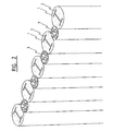
- step A an array of 4 primary piles 1, which piles 1 are at a mutual pitch distance of S1. These piles 1 are obtained in each case by on-site mixing of a pile-shaped space with a curing mixture, whereafter a reinforcing profile 2 is placed in the array of primary piles 1.
- At least one secondary pile-shaped space is then bored in the ground in each case between each pair of adjacent primary piles 1 and filled with concrete in order to obtain an array of secondary piles 3.
- the pitch distance S1 between primary piles 1 is sealed by a secondary pile 3.
- Two of the three shown secondary piles 3 are provided with an anchor 4 such that the forces exerted transversely of secondary pile 3 are transmitted to the reinforcing profiles 2.
- the secondary pile preferably has a diameter D2 which is smaller than or equal to that of the primary pile D1, and the centre lines of the array of secondary piles 3 preferably lie in a plane at a distance S2 from the centre lines of the primary piles 1. In this manner the primary piles 1 and the secondary piles 2 adjoin the same outer plane.
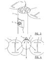
- FIGS 3 and 4 illustrate in detail an anchor mounted on a secondary pile.
- Anchor 4 protrudes through the secondary pile 3 on which the anchor 4 is mounted by means of a supporting plate 5 and a screw 6.
- Such a construction guarantees a good transmission to reinforcing profiles 2 of the forces exerted on anchor 4.
- Figure 5 shows a yoke 7 which is arranged against the periphery 8 formed by primary piles 1 and secondary piles 3. On this yoke 7 can engage stabilizing members such as an anchor or strut.
- the array of secondary piles 3 is formed such that the outer periphery 8 with which the secondary piles 3 make contact substantially coincides with outer side 9 of reinforcing profiles 2. This side 9 of reinforcing profiles 2 is exposed, and in the embodiment of figure 5 the yoke 7 supports directly against these sides 9 of reinforcing profiles 2.
- Figure 6 shows a known device for on-site mixing of a pile-shaped space. During the drilling the shaft 14 of the boring unit is moved downward along shaft 16 and then back up again.
- Figures 7 and 8 show details of the boring apparatus which can for instance be used to obtain the primary piles 1 of the embodiment of figure 1.
- the boring apparatus must be placed for this purpose at the position of the pile-shaped space for boring, whereupon the boring, in combination with injection of binder, is carried out to the desired depth, which can for instance be 18 metres.
- the drill is then brought back up while further mixing the soil with the binder.
- the boring apparatus shown in figures 7 and 8 for boring with on-site mixing of the soil with a binder consists substantially of a drive shaft 14 with cutting and mixing blades 15 placed transversely thereof. Mounted on the outer end of shaft 14 is a drilling end 10, above which are arranged spiral-shaped blades 12 provided with injection nozzles 11 for the binder. Recesses 13 are arranged in spiral-shaped blades 12. These recesses 13 ensure a good mixing of the soil with the binder coming from injection nozzles 11.
- the pitch S3 of the spiral-shaped blades 12 is preferably roughly equal to the diameter D3 thereof.
- Such a ratio of S3/D3 guarantees a good mixing of the binder and the soil, so that the pile is constructed from a relatively homogeneous material.
Landscapes
- Engineering & Computer Science (AREA)
- Structural Engineering (AREA)
- Life Sciences & Earth Sciences (AREA)
- General Life Sciences & Earth Sciences (AREA)
- Mining & Mineral Resources (AREA)
- Paleontology (AREA)
- Civil Engineering (AREA)
- General Engineering & Computer Science (AREA)
- Piles And Underground Anchors (AREA)
- Bulkheads Adapted To Foundation Construction (AREA)
Applications Claiming Priority (2)
| Application Number | Priority Date | Filing Date | Title |
|---|---|---|---|
| BE2002/0634A BE1015173A5 (nl) | 2002-11-06 | 2002-11-06 | Werkwijze voor het bouwen van een beschoeiing. |
| BE200200634 | 2002-11-06 |
Publications (1)
| Publication Number | Publication Date |
|---|---|
| EP1418277A1 true EP1418277A1 (fr) | 2004-05-12 |
Family
ID=32097283
Family Applications (1)
| Application Number | Title | Priority Date | Filing Date |
|---|---|---|---|
| EP03078471A Withdrawn EP1418277A1 (fr) | 2002-11-06 | 2003-11-04 | Procédé de construction d'un mur de soutènement |
Country Status (2)
| Country | Link |
|---|---|
| EP (1) | EP1418277A1 (fr) |
| BE (1) | BE1015173A5 (fr) |
Cited By (6)
| Publication number | Priority date | Publication date | Assignee | Title |
|---|---|---|---|---|
| EP1600561A1 (fr) * | 2004-05-26 | 2005-11-30 | Etienne Heirwegh | Rideau de palplanches résistant à l'eau forme in-situ et son procede de fabrication |
| EP1757771A3 (fr) * | 2005-08-23 | 2007-10-24 | Trevi S.p.A. | Procédé pour consolider et imperméabiliser le sol autour d'un tunnel |
| EP2003251A1 (fr) * | 2002-09-19 | 2008-12-17 | Sigma Consult GmbH | Avant-corps de support |
| WO2015128515A1 (fr) * | 2014-02-28 | 2015-09-03 | Universidad De Granada | Pieu ayant un profil à section monosymétrique pour retenir des terres |
| JP2017031727A (ja) * | 2015-08-04 | 2017-02-09 | 株式会社大林組 | 山留め壁の変形抑止構造および山留め壁の変形抑止工法 |
| CN107503356A (zh) * | 2017-08-18 | 2017-12-22 | 昆明理工大学 | 一种应用于松软土层中控制基坑支护结构成型方法 |
Citations (7)
| Publication number | Priority date | Publication date | Assignee | Title |
|---|---|---|---|---|
| US3969902A (en) * | 1973-07-23 | 1976-07-20 | Yoshino Ichise | Contruction method for continuous row of piles and earth drill for use therefor |
| JPS5988537A (ja) * | 1982-11-10 | 1984-05-22 | Sekisui Plastics Co Ltd | 柱列土留用鋼材の引抜き方法 |
| US4537536A (en) * | 1983-10-18 | 1985-08-27 | The Shimizu Construction Co., Ltd. | Process and apparatus of constructing a water tight underground pile wall |
| GB2178461A (en) * | 1985-06-11 | 1987-02-11 | Stent Foundations Limited | Retaining walls |
| US5934840A (en) * | 1997-10-03 | 1999-08-10 | Geocon | Excavation support structure |
| EP1045073A1 (fr) * | 1999-04-15 | 2000-10-18 | TREVI S.p.A. | Outil d'excavation et procédé de fabrication d'une colonne en sol consolidée |
| US6241426B1 (en) * | 1999-05-25 | 2001-06-05 | Aerial Industrial, Inc. | Method for forming an interconnected underground structure |
-
2002
- 2002-11-06 BE BE2002/0634A patent/BE1015173A5/nl not_active IP Right Cessation
-
2003
- 2003-11-04 EP EP03078471A patent/EP1418277A1/fr not_active Withdrawn
Patent Citations (7)
| Publication number | Priority date | Publication date | Assignee | Title |
|---|---|---|---|---|
| US3969902A (en) * | 1973-07-23 | 1976-07-20 | Yoshino Ichise | Contruction method for continuous row of piles and earth drill for use therefor |
| JPS5988537A (ja) * | 1982-11-10 | 1984-05-22 | Sekisui Plastics Co Ltd | 柱列土留用鋼材の引抜き方法 |
| US4537536A (en) * | 1983-10-18 | 1985-08-27 | The Shimizu Construction Co., Ltd. | Process and apparatus of constructing a water tight underground pile wall |
| GB2178461A (en) * | 1985-06-11 | 1987-02-11 | Stent Foundations Limited | Retaining walls |
| US5934840A (en) * | 1997-10-03 | 1999-08-10 | Geocon | Excavation support structure |
| EP1045073A1 (fr) * | 1999-04-15 | 2000-10-18 | TREVI S.p.A. | Outil d'excavation et procédé de fabrication d'une colonne en sol consolidée |
| US6241426B1 (en) * | 1999-05-25 | 2001-06-05 | Aerial Industrial, Inc. | Method for forming an interconnected underground structure |
Non-Patent Citations (1)
| Title |
|---|
| PATENT ABSTRACTS OF JAPAN vol. 008, no. 201 (M - 325) 14 September 1984 (1984-09-14) * |
Cited By (6)
| Publication number | Priority date | Publication date | Assignee | Title |
|---|---|---|---|---|
| EP2003251A1 (fr) * | 2002-09-19 | 2008-12-17 | Sigma Consult GmbH | Avant-corps de support |
| EP1600561A1 (fr) * | 2004-05-26 | 2005-11-30 | Etienne Heirwegh | Rideau de palplanches résistant à l'eau forme in-situ et son procede de fabrication |
| EP1757771A3 (fr) * | 2005-08-23 | 2007-10-24 | Trevi S.p.A. | Procédé pour consolider et imperméabiliser le sol autour d'un tunnel |
| WO2015128515A1 (fr) * | 2014-02-28 | 2015-09-03 | Universidad De Granada | Pieu ayant un profil à section monosymétrique pour retenir des terres |
| JP2017031727A (ja) * | 2015-08-04 | 2017-02-09 | 株式会社大林組 | 山留め壁の変形抑止構造および山留め壁の変形抑止工法 |
| CN107503356A (zh) * | 2017-08-18 | 2017-12-22 | 昆明理工大学 | 一种应用于松软土层中控制基坑支护结构成型方法 |
Also Published As
| Publication number | Publication date |
|---|---|
| BE1015173A5 (nl) | 2004-10-05 |
Similar Documents
| Publication | Publication Date | Title |
|---|---|---|
| AU724933B2 (en) | Method and apparatus for forming piles in-situ | |
| CA2809638C (fr) | Coques extensibles et procedes associes pour la construction d'un pilier porteur | |
| US20060088388A1 (en) | Method and apparatus for providing a rammed aggregate pier | |
| US6655107B2 (en) | Method for reinforcing hollow concrete block walls | |
| US9243379B2 (en) | Method of providing a support column | |
| KR20080077721A (ko) | 옹벽용 블록 축조방법 | |
| CN106192999A (zh) | 抗拔桩的施工方法 | |
| EP3318677B1 (fr) | Méthode de formation d'un pieu renforcé et utilisation d'un accessoire selon la méthode | |
| US7044686B2 (en) | Apparatus and method for supporting a structure with a pier | |
| EP1418277A1 (fr) | Procédé de construction d'un mur de soutènement | |
| WO2010130009A1 (fr) | Ensemble pile et son procédé de production | |
| KR20100030241A (ko) | 콤팩션 그라우팅 공법 | |
| KR102023135B1 (ko) | 팔각 케이싱을 이용한 흙막이 공법 | |
| EP3638853B1 (fr) | Système pour installer des pieux supports ductiles dans le sol et procédé associé | |
| KR102156277B1 (ko) | 연약지반의 기초 파일 시공 방법 및 이에 적용되는 연약지반의 기초 파일장치 | |
| KR102059051B1 (ko) | 수직구 굴착방법 | |
| KR100533612B1 (ko) | 설치와 해체가 용이한 건축용토류판 | |
| EP1070793A1 (fr) | Procédé de formation d'une barrette dans le sol et barrette ainsi obtenue | |
| JP4146250B2 (ja) | オープンケーソンの底盤築造方法 | |
| CN213952205U (zh) | 一种cfg桩复合地基施工装置 | |
| CN212200403U (zh) | 一种预应力管桩结构 | |
| CN108252533A (zh) | 一种离散型砖砌平台的整体托换方法 | |
| KR200245393Y1 (ko) | 조립식 반달형 골판틀을 이용한 교각기초 매립식 흙막이구조 | |
| CN121630235A (zh) | 一种引孔回填式钢板桩支护装置及施工方法 | |
| CN116201134A (zh) | 一种静压斜桩支护结构及其施工方法 |
Legal Events
| Date | Code | Title | Description |
|---|---|---|---|
| PUAI | Public reference made under article 153(3) epc to a published international application that has entered the european phase |
Free format text: ORIGINAL CODE: 0009012 |
|
| AK | Designated contracting states |
Kind code of ref document: A1 Designated state(s): AT BE BG CH CY CZ DE DK EE ES FI FR GB GR HU IE IT LI LU MC NL PT RO SE SI SK TR |
|
| AX | Request for extension of the european patent |
Extension state: AL LT LV MK |
|
| 17P | Request for examination filed |
Effective date: 20041104 |
|
| AKX | Designation fees paid |
Designated state(s): AT BE BG CH CY CZ DE DK EE ES FI FR GB GR HU IE IT LI LU MC NL PT RO SE SI SK TR |
|
| RAP1 | Party data changed (applicant data changed or rights of an application transferred) |
Owner name: SMET, LUC MARIA HUGO CORNEEL |
|
| RIN1 | Information on inventor provided before grant (corrected) |
Inventor name: SMET, LUC MARIA HUGO CORNEEL |
|
| 17Q | First examination report despatched |
Effective date: 20061117 |
|
| STAA | Information on the status of an ep patent application or granted ep patent |
Free format text: STATUS: THE APPLICATION IS DEEMED TO BE WITHDRAWN |
|
| 18D | Application deemed to be withdrawn |
Effective date: 20070328 |