EP1418285B1 - Ineinandergreifende Elemente - Google Patents
Ineinandergreifende Elemente Download PDFInfo
- Publication number
- EP1418285B1 EP1418285B1 EP02079703A EP02079703A EP1418285B1 EP 1418285 B1 EP1418285 B1 EP 1418285B1 EP 02079703 A EP02079703 A EP 02079703A EP 02079703 A EP02079703 A EP 02079703A EP 1418285 B1 EP1418285 B1 EP 1418285B1
- Authority
- EP
- European Patent Office
- Prior art keywords
- elements
- vertical
- interlocking
- construction
- base
- Prior art date
- Legal status (The legal status is an assumption and is not a legal conclusion. Google has not performed a legal analysis and makes no representation as to the accuracy of the status listed.)
- Expired - Lifetime
Links
Images

Classifications
-
- E—FIXED CONSTRUCTIONS
- E04—BUILDING
- E04C—STRUCTURAL ELEMENTS; BUILDING MATERIALS
- E04C1/00—Building elements of block or other shape for the construction of parts of buildings
- E04C1/39—Building elements of block or other shape for the construction of parts of buildings characterised by special adaptations, e.g. serving for locating conduits, for forming soffits, cornices, or shelves, for fixing wall-plates or door-frames, for claustra
- E04C1/395—Building elements of block or other shape for the construction of parts of buildings characterised by special adaptations, e.g. serving for locating conduits, for forming soffits, cornices, or shelves, for fixing wall-plates or door-frames, for claustra for claustra, fences, planting walls, e.g. sound-absorbing
-
- E—FIXED CONSTRUCTIONS
- E02—HYDRAULIC ENGINEERING; FOUNDATIONS; SOIL SHIFTING
- E02D—FOUNDATIONS; EXCAVATIONS; EMBANKMENTS; UNDERGROUND OR UNDERWATER STRUCTURES
- E02D17/00—Excavations; Bordering of excavations; Making embankments
- E02D17/18—Making embankments, e.g. dikes, dams
-
- E—FIXED CONSTRUCTIONS
- E02—HYDRAULIC ENGINEERING; FOUNDATIONS; SOIL SHIFTING
- E02D—FOUNDATIONS; EXCAVATIONS; EMBANKMENTS; UNDERGROUND OR UNDERWATER STRUCTURES
- E02D29/00—Independent underground or underwater structures; Retaining walls
- E02D29/02—Retaining or protecting walls
- E02D29/025—Retaining or protecting walls made up of similar modular elements stacked without mortar
-
- E—FIXED CONSTRUCTIONS
- E04—BUILDING
- E04B—GENERAL BUILDING CONSTRUCTIONS; WALLS, e.g. PARTITIONS; ROOFS; FLOORS; CEILINGS; INSULATION OR OTHER PROTECTION OF BUILDINGS
- E04B2/00—Walls, e.g. partitions, for buildings; Wall construction with regard to insulation; Connections specially adapted to walls
- E04B2/02—Walls, e.g. partitions, for buildings; Wall construction with regard to insulation; Connections specially adapted to walls built-up from layers of building elements
- E04B2002/0202—Details of connections
- E04B2002/0204—Non-undercut connections, e.g. tongue and groove connections
Definitions
- the present invention relates to construction materials, and more particularly to a multi-directional, interlocking, hollow modular building element designed to increase stability of load-bearing walls or structures and minimize active pressure.
- the active vertical and horizontal pressure of the filling material must be taken into consideration.
- the width of the slope needed to absorb the active pressure exerted by the filling material is proportional to the height of the filling material.
- Load-bearing retaining walls, supports and other similar structures have traditionally been constructed of concrete poured at the site, a process which is time-consuming and labor-intensive.
- precast building blocks have been developed for use in erecting retaining walls, supports and the like, some of which are suggested for use in constructing a bridge abutment.
- US patent 4982544 to Smith there is described a precast concrete module for use in constructing retaining walls capable of sustaining large vertical loads.
- a stabilizing means is required, such as metal sheets inserted through slots in the rear connecting walls.
- the module described by Smith has a front wall, a partition wall, at least two front connecting walls and a rear connecting wall. The region between the front walls and the partition walls of the assembled modules is filled with poured concrete to create a load-bearing retaining wall. The step of pouring concrete is again time-consuming.
- a particularly advantageous type of building block is that in which individual elements interlock, forming a secure, stable structure requiring little or no cement or other adhesive material, thus reducing the cost of material and time required for construction.
- many of these blocks comprise a solid unit and do not have internal cavities to facilitate the placement of insulation, pipes or conduits.
- the use of filling material, which may be used to add weight to the modules is prevented. This may be a particular disadvantage in the case of a retaining wall in which such filling could add weight to the modules to counteract the forces exerted by fill to the rear of the wall.
- a system of modular interlocking building elements comprising a plurality of rigid, hollow polygonal elements, having vertical faces, a first portion of said polygonal elements provided as base elements arranged as a base layer, a second portion of said polygonal elements provided as interlocking elements arranged as an intermediate layer above said base layer, a third portion of said polygonal elements provided as interlocking elements arranged as an upper layer above said intermediate layer, said interlocking elements in said intermediate layer being formed with a vertical slit in all of said vertical faces, said interlocking elements in said upper layer being formed with vertical slits in at least two of said vertical faces, such that said at least two vertical slits of each of said intermediate layer elements engage said base elements, and said at least two vertical slits of each of said upper layer elements engage said intermediate layer elements, said base, upper and intermediate layers providing a mortarless, multidirectional, load-bearing construction.
- a series of interlocking, quadrilateral, hollow, elements each provided with vertical slits for engaging the upper half of the face of one or two similar modular elements.
- the interlocking elements form a continuous structure, which will counteract the active pressure exerted by any filling material.
- the load exerted on the structure develops forces which are constrained within the element and these forces are not spread horizontally to the surrounding foundation.
- a feature of the present invention is to provide modular elements for use in construction of structures in which active pressure is a factor, such as retaining walls, bridge abutments, ramps, dams, artificial islands, etc.
- An advantage of the present invention is the minimization of active pressure, resulting in economization on filling material, ground area, area of foundations, etc.
- a further advantage of the present invention is that the interlocking structure of the elements enables construction in all directions, permitting even load distribution and adding to the load-bearing capacity of the entire construction.
- the vertical and horizontal interlocking enables the construction of an even surface without the use of adhesive material between the elements.
- the modular elements of the present invention may also be used as building construction elements without filling material, for example in the construction of overhead passageways.
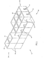
- Fig. 1 shows a perspective view of a construction 10 using a series of modular elements 12.
- the elements 12 are hollow, quadrilateral framing elements, provided as blocks, typically known as construction blocks, having only vertical faces, with no upper or lower horizontal face.
- the elements 12 are square, but other shapes, such as rectangles or polygonal shapes, by way of example, may also be used.
- the elements 12 may be constructed, by way of example, from concrete, iron, or any other material appropriate to the present purpose.
- the blocks may be of any size, for example with faces having length between 0.2 meters up to several meters. Variations of elements 12 are denoted as elements 16, 28, 22 and 24, as described in detail below.
- Fig. 1 shows an incomplete construction 10 comprising a system of various quadrilateral elements 12.
- Vertical slits 14 are formed on the vertical faces of elements 12, extending upwards from the mid-point of the lower edge of the vertical face.
- the width of slits 14 is equivalent to the width of the walls of element 12.
- the number of vertical slits 14 formed on the vertical faces of each element 12 may differ, as described further below.
- Vertical slits 14 are designed to enable interlocking arrangement of layers of elements.
- the framing elements 16 which form the base layer of construction 10 have four smooth faces 20 with no vertical slits.
- the elements 16 of base layer 30 are first arranged in the required formation.
- Elements 12 of second layer 32 are then positioned with slits 14 over the horizontal mid-point of the wall of an element 12 of the base layer 30, so that the wall of the lower element 16 becomes engaged within vertical slit 14 of the upper layer element 12. Since the width of slit 14 of element 12 is equivalent to the thickness of the wall of lower element 16, element 16 is firmly and tightly engaged within slit 14.
- Elements 28, having four slits 14 are used for placement over arrangements of four base elements 16, as further described below with reference to Fig. 5.
- the elements 22 and 24, which are included in layers above the base, have respectively one and two smooth faces 20 having no slit 14. In this fashion, interlocking arrangement of elements 16, 22 and 24 on the outer perimeter can be achieved with faces 20 placed in an outward-facing position to form a smooth, continuous outer surface.
- Element 22 is intended for placement so as to be surrounded on three sides by other elements 22 or 24, with only one face 20 forming an outer surface of construction 10.
- Comer element 24 is designed to be positioned with adjacent elements 22 or 24 on two sides, therefore leaving two surfaces exposes.
- Vertical slit 14 is of length equal to half the height of the vertical face in which it is formed, so that when three layers are interlockingly arranged one upon the other, the lower edges of the wall of the uppermost layer rests directly upon the uppermost edge of the lowest layer, thereby leaving no gap.
- the modular elements are hollow, enabling the addition of filling material as required.
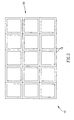
- FIG. 2 a top view of the base layer 30 of the construction 10 is shown.
- a series of hollow, quadrilateral elements 16, having no vertical slits, are placed side by side in the required arrangement, which in this example forms a rectangular arrangement.
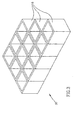
- Fig. 3 shows a perspective view of the elements 16 of base layer 30, arranged so as to form a construction having irregular shape.
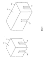
- Fig. 4 shows elements 28, having a slit 14 on each of four vertical faces.
- Element 28 is designed to interlock with four elements 12, where the four elements 12 are arranged so as to form a square, which will hold the four elements 12 in a stable arrangement, requiring no mortar or other stabilizing material.
- Element 28, which is used in intermediate layer 32, does not extend to the outer perimeter of construction 10.
- Element 28 is also used in the interior of upper layer 34, in which case elements 28 will be surrounded by elements 22 and 24, located on the outer perimeter.
- Fig. 5 shows a construction 10, in which the elements 28 of the upper layer 32 are arranged upon the base layer 30.
- Elements 28 have a slit 14 in each of their four vertical faces.
- Each element 28 is placed over a group of four elements 16 arranged so as to form a square, so that the central point of the square formed by the four elements 16 coincides with the central point of element 28.
- each slit 14 holds together a side of each of two adjacent elements 16 and four elements 16 of base layer 30 are held within each second-layer element 28.
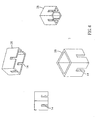
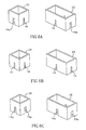
- Fig. 6a shows a modular element 22 having three slits, where slit 14a is designed to engage the walls of two adjacent lower layer elements and is therefore double the width of slits 14 which engage only one lower layer element wall.
- the shape of element 22 may be square or rectangular.
- Fig. 6b shows modular comer element 24 having two slits 14, each of which engages one wall of a lower layer element.
- Fig. 6c shows modular elements 28 having four slits 14a, each of which engage the adjacent walls of each of two lower level elements.
- Fig. 7 shows the modular elements 40 of the uppermost layer of construction 10, in which an upper horizontal surface 42 is provided, forming a closed upper surface.
- constructions 10 illustrate the flexibility of the interlocking construction system of the present invention, whereby continuation of construction can proceed along the direction of any or all of the four faces of an element 12, as well as in an upward direction.
- the variations in the number of slits enable the various constructions to be formed having a smooth, continuous, outer surface, if so required.
- the hollow, framing structure of the elements enables the construction 10 to be filled after assembly with filling material, and to absorb or minimize the active pressure generated thereby.
- Filling material may be used, for example in the case of a retaining wall, to add weight to the modules to counteract forces exerted on the rear of the wall.
- constructions without filling may be built, without filling, such as in the construction of overhead passageways.
- the design of the modules allows even weight distribution over the entire structure, thus creating a high load-bearing capacity.
- interlocking arrangement of elements results in a stable construction, without need for mortar or other stabilizing material, increasing the speed and efficiency with which the construction can be erected, and also reducing the overall cost of materials.
- modular construction elements of the present invention such as retaining walls, ramps, artificial islands, overhead passageways etc.
- the system may also be used as bridge abutments. If the construction is to be built within a system of water, such as in a river, openings may be provided in the base layer of elements to enable passage of water.
Landscapes
- Engineering & Computer Science (AREA)
- Civil Engineering (AREA)
- Mining & Mineral Resources (AREA)
- Structural Engineering (AREA)
- General Engineering & Computer Science (AREA)
- Paleontology (AREA)
- General Life Sciences & Earth Sciences (AREA)
- Life Sciences & Earth Sciences (AREA)
- Architecture (AREA)
- Environmental & Geological Engineering (AREA)
- Revetment (AREA)
- Control Of Motors That Do Not Use Commutators (AREA)
- Fixed Capacitors And Capacitor Manufacturing Machines (AREA)
- Pharmaceuticals Containing Other Organic And Inorganic Compounds (AREA)
- Finishing Walls (AREA)
Claims (17)
- System von modularen, ineinandergreifenden Einrahmungselementen, das imstande ist, Füllmaterial aufzunehmen und den dadurch erzeugten Wirkdruck zu absorbieren, wobei das System folgendes umfasst:mehrere starre, hohle, vieleckige Einrahmungselemente (16, 28, 22, 24, 40, 12), die jedes mehrere nur vertikale Seiten aufweisen, welche an ihren Kanten verbunden sind,wobei ein erster Abschnitt der vieleckigen Elemente als Grundelemente vorgesehen ist, welche als Grundschicht angeordnet sind,wobei ein zweiter Abschnitt der vieleckigen Elemente als ineinandergreifende Elemente vorgesehen ist, welche als Zwischenschicht über der Grundschicht angeordnet sind,wobei ein dritter Abschnitt der vieleckigen Elemente (40) als ineinandergreifende Elemente vorgesehen ist, welche als Oberschicht über der Zwischenschicht angeordnet sind,wobei die ineinandergreifenden Elemente in der Zwischenschicht mit einem einzelnen, vertikalen Schlitz (14, 14a) ausgebildet sind, der vom Mittelpunkt der unteren Kante jeder der vertikalen Seiten aufwärts verläuft, wobei der vertikale Schlitz eine Höhe, die gleich der halben Höhe der vertikalen Seite ist, und eine Breite aufweist, die der Gesamtstärke der Wand der Grundschichtelemente entspricht, die darin eingefügt sein soll,wobei die ineinandergreifenden Elemente in der Oberschicht mit einem einzelnen, vertikalen Schlitz (14, 14a) ausgebildet sind, der vom Mittelpunkt der unteren Kante von zumindest zwei der vertikalen Seiten aufwärts verläuft, wobei der vertikale Schlitz eine Höhe, die gleich der halben Höhe der vertikalen Seite ist, und eine Breite aufweist, die der Gesamtstärke von einer oder zwei der Wände der Zwischenschichtelemente entspricht, die darin eingefügt sein sollen, soweit angemessen,sodass jeder der vertikalen Schlitze, die in der vertikalen Seite der Zwischenschichtelemente ausgebildet sind, die Grundelemente an einem horizontalen Mittelpunkt der vertikalen Seite der Grundelemente in Eingriff nimmtund jeder der vertikalen Schlitze, die in den vertikalen Seiten von jedem der Oberschichtelemente ausgebildet sind, die Zwischenschichtelemente an einem horizontalen Mittelpunkt der vertikalen Seite der Zwischenschichtelemente in Eingriff nimmt,sodass die Grundschichtelemente zum Ausbilden einer gleichmäßigen, fortlaufenden Außenfläche an den Oberschichtelementen ausgerichtet sind,wobei die Grund-, Ober- und Zwischenschicht einen mörtellosen, multidirektionalen, tragenden Bau vorsieht.
- System nach Anspruch 1, wobei die Oberschichtelemente einen Abschnitt von Elementen mit zumindest einer gleichmäßigen Außenfläche beinhalten, die als Außenumfang der Oberschicht angeordnet sein sollen, sodass der multidirektionale, tragende Bau mit einer gleichmäßigen, fortlaufenden Außenfläche ausgebildet ist.
- System nach Anspruch 1, wobei mehrere der Oberschichten in einer versetzten Anordnung auf mehreren der Zwischenschichten gestapelt sind.
- System nach Anspruch 1, wobei die ineinandergreifenden Bauelemente vierseitig sind.
- System nach Anspruch 1, wobei die mehreren ineinandergreifenden Elemente mit einem vertikalen Schlitz in jeder von zwei vertikalen Seiten ausgebildet sind.
- System nach Anspruch 1, wobei die mehreren ineinandergreifenden Elemente mit einem vertikalen Schlitz in jeder von drei vertikalen Seiten ausgebildet sind.
- System nach Anspruch 1, beinhaltend mehrere ineinandergreifende Einheiten, die mit einem vertikalen Schlitz in jeder von vier vertikalen Seiten ausgebildet sind.
- System nach Anspruch 1, wobei die ineinandergreifenden Elemente ferner eine horizontale obere Fläche umfassen.
- System nach Anspruch 1, wobei die ineinandergreifenden Elemente rechteckig sind.
- System nach Anspruch 1 zum Gebrauch beim Bau einer Stützmauer.
- System nach Anspruch 1 zum Gebrauch beim Bau einer Rampe.
- System nach Anspruch 1 zum Gebrauch beim Bau einer künstlichen Insel.
- System nach Anspruch 1 zum Gebrauch beim Bau eines Brückenwiderlagers.
- System nach Anspruch 1 zum Gebrauch beim Bau eines Damms .
- System nach Anspruch 1 zum Gebrauch beim Bau von hochliegenden Durchgängen.
- System nach Anspruch 1, wobei die vieleckigen Elemente jeweils mit Füllmaterial gefüllt sind.
- System nach Anspruch 1, wobei die Grundelemente mit Öffnungen für den Durchlauf von Wasser versehen sind.
Priority Applications (3)
| Application Number | Priority Date | Filing Date | Title |
|---|---|---|---|
| EP02079703A EP1418285B1 (de) | 2002-11-08 | 2002-11-08 | Ineinandergreifende Elemente |
| AT02079703T ATE383477T1 (de) | 2002-11-08 | 2002-11-08 | Ineinandergreifende elemente |
| DE60224542T DE60224542D1 (de) | 2002-11-08 | 2002-11-08 | Ineinandergreifende Elemente |
Applications Claiming Priority (1)
| Application Number | Priority Date | Filing Date | Title |
|---|---|---|---|
| EP02079703A EP1418285B1 (de) | 2002-11-08 | 2002-11-08 | Ineinandergreifende Elemente |
Publications (2)
| Publication Number | Publication Date |
|---|---|
| EP1418285A1 EP1418285A1 (de) | 2004-05-12 |
| EP1418285B1 true EP1418285B1 (de) | 2008-01-09 |
Family
ID=32103988
Family Applications (1)
| Application Number | Title | Priority Date | Filing Date |
|---|---|---|---|
| EP02079703A Expired - Lifetime EP1418285B1 (de) | 2002-11-08 | 2002-11-08 | Ineinandergreifende Elemente |
Country Status (3)
| Country | Link |
|---|---|
| EP (1) | EP1418285B1 (de) |
| AT (1) | ATE383477T1 (de) |
| DE (1) | DE60224542D1 (de) |
Families Citing this family (1)
| Publication number | Priority date | Publication date | Assignee | Title |
|---|---|---|---|---|
| DE102006028976B4 (de) * | 2006-06-23 | 2012-02-23 | Factum Gmbh | Damm |
Family Cites Families (15)
| Publication number | Priority date | Publication date | Assignee | Title |
|---|---|---|---|---|
| US834950A (en) * | 1905-08-07 | 1906-11-06 | Elmer E Van Wie | Building-tube. |
| US4075808A (en) | 1974-11-25 | 1978-02-28 | Sanford Pearlman | Building construction system using mortar-less modular building block elements |
| US3936987A (en) | 1975-01-13 | 1976-02-10 | Edward L Calvin | Interlocking brick or building block and walls constructed therefrom |
| US4031678A (en) | 1975-11-20 | 1977-06-28 | Schuring James A | Interlocking building block construction |
| US4815897A (en) | 1982-08-16 | 1989-03-28 | Rothbury Investments Limited | Retaining wall system |
| US4573301A (en) | 1983-02-18 | 1986-03-04 | Wilkinson Rudolph P | Interlocking building blocks |
| US4514949A (en) | 1983-05-06 | 1985-05-07 | Crespo Jorge L N | Interlocking system for building walls |
| US4601148A (en) * | 1983-06-24 | 1986-07-22 | Angelo Risi | Module for walls and free standing structure |
| US4481155A (en) * | 1983-10-19 | 1984-11-06 | Ceramic Cooling Tower Company | Multi-cell tiles with openings for use in a liquid cooling tower |
| US4627209A (en) | 1985-04-15 | 1986-12-09 | Schwartz Ervin J | Interlocking blocks and construction system comprising said blocks |
| US4651485A (en) | 1985-09-11 | 1987-03-24 | Osborne Ronald P | Interlocking building block system |
| US4982544A (en) | 1988-12-12 | 1991-01-08 | Pomico International, Inc. | Module and method for constructing sealing load-bearing retaining wall |
| FR2669956B1 (fr) | 1990-11-29 | 1997-12-12 | Brandom Ste Civile | Element et procede de construction sans mortier. |
| US5181362A (en) | 1991-09-16 | 1993-01-26 | Benitez Rafael C | Interlocking building blocks |
| CA2060379A1 (en) | 1992-01-30 | 1993-07-31 | Peter R. Pitchford | Interlocking building block |
-
2002
- 2002-11-08 AT AT02079703T patent/ATE383477T1/de not_active IP Right Cessation
- 2002-11-08 DE DE60224542T patent/DE60224542D1/de not_active Expired - Lifetime
- 2002-11-08 EP EP02079703A patent/EP1418285B1/de not_active Expired - Lifetime
Also Published As
| Publication number | Publication date |
|---|---|
| ATE383477T1 (de) | 2008-01-15 |
| EP1418285A1 (de) | 2004-05-12 |
| DE60224542D1 (de) | 2008-02-21 |
Similar Documents
| Publication | Publication Date | Title |
|---|---|---|
| US6477814B1 (en) | Modular interlocking framing elements | |
| US4319440A (en) | Building blocks, wall structures made therefrom and methods of making the same | |
| CA2741405C (en) | Modular construction system and components and method | |
| US5623797A (en) | Block structure and system for arranging above-ground fencing, railing and/or sound barriers | |
| US4653962A (en) | Retaining wall construction and method of manufacture | |
| CA2694101C (en) | Framing structure | |
| US4982544A (en) | Module and method for constructing sealing load-bearing retaining wall | |
| US20120167502A1 (en) | Modular construction system and components and method | |
| US8863465B2 (en) | Stackable wall block system | |
| US5315802A (en) | Modular wall system | |
| EP1846629A2 (de) | Stützwandblocksystem | |
| EP0392861A1 (de) | Verfahren und Mittel zur Herstellung einer Mauer aus Ziegelstein | |
| US5992102A (en) | Cellular resin block and structural unit for an exterior structure using such block | |
| US5030035A (en) | Earth retaining system | |
| US9410314B1 (en) | Modular floodwall construction elements | |
| EP1418285B1 (de) | Ineinandergreifende Elemente | |
| JP7160357B2 (ja) | 壁モジュールによる構造物の製造方法 | |
| IL132447A (en) | Combined modular elements for building | |
| JP4524490B2 (ja) | 傾斜地保全型建物およびその構築方法 | |
| JP2022172731A (ja) | 梯子状に固定した成型部材で造るコンクリート擁壁。 | |
| JPH0543012B2 (de) | ||
| JP7396660B2 (ja) | 耐震用レンガ及びそれを用いたレンガ構造物 | |
| IE20180152A1 (en) | A foundation and rising wall insulated construction system. | |
| JP2000144976A (ja) | 構造用ブロック | |
| CN116856450A (zh) | 一种可周转标准箱式房混凝土基础装置及其施工方法 |
Legal Events
| Date | Code | Title | Description |
|---|---|---|---|
| PUAI | Public reference made under article 153(3) epc to a published international application that has entered the european phase |
Free format text: ORIGINAL CODE: 0009012 |
|
| AK | Designated contracting states |
Kind code of ref document: A1 Designated state(s): AT BE BG CH CY CZ DE DK EE ES FI FR GB GR IE IT LI LU MC NL PT SE SK TR |
|
| AX | Request for extension of the european patent |
Extension state: AL LT LV MK RO SI |
|
| 17P | Request for examination filed |
Effective date: 20041110 |
|
| AKX | Designation fees paid |
Designated state(s): AT BE BG CH CY CZ DE DK EE ES FI FR GB GR IE IT LI LU MC NL PT SE SK TR |
|
| GRAP | Despatch of communication of intention to grant a patent |
Free format text: ORIGINAL CODE: EPIDOSNIGR1 |
|
| GRAS | Grant fee paid |
Free format text: ORIGINAL CODE: EPIDOSNIGR3 |
|
| GRAA | (expected) grant |
Free format text: ORIGINAL CODE: 0009210 |
|
| AK | Designated contracting states |
Kind code of ref document: B1 Designated state(s): AT BE BG CH CY CZ DE DK EE ES FI FR GB GR IE IT LI LU MC NL PT SE SK TR |
|
| REG | Reference to a national code |
Ref country code: GB Ref legal event code: FG4D |
|
| REG | Reference to a national code |
Ref country code: CH Ref legal event code: EP |
|
| REG | Reference to a national code |
Ref country code: IE Ref legal event code: FG4D |
|
| REF | Corresponds to: |
Ref document number: 60224542 Country of ref document: DE Date of ref document: 20080221 Kind code of ref document: P |
|
| PG25 | Lapsed in a contracting state [announced via postgrant information from national office to epo] |
Ref country code: NL Free format text: LAPSE BECAUSE OF FAILURE TO SUBMIT A TRANSLATION OF THE DESCRIPTION OR TO PAY THE FEE WITHIN THE PRESCRIBED TIME-LIMIT Effective date: 20080109 |
|
| NLV1 | Nl: lapsed or annulled due to failure to fulfill the requirements of art. 29p and 29m of the patents act | ||
| PG25 | Lapsed in a contracting state [announced via postgrant information from national office to epo] |
Ref country code: LI Free format text: LAPSE BECAUSE OF FAILURE TO SUBMIT A TRANSLATION OF THE DESCRIPTION OR TO PAY THE FEE WITHIN THE PRESCRIBED TIME-LIMIT Effective date: 20080109 Ref country code: ES Free format text: LAPSE BECAUSE OF FAILURE TO SUBMIT A TRANSLATION OF THE DESCRIPTION OR TO PAY THE FEE WITHIN THE PRESCRIBED TIME-LIMIT Effective date: 20080420 Ref country code: CH Free format text: LAPSE BECAUSE OF FAILURE TO SUBMIT A TRANSLATION OF THE DESCRIPTION OR TO PAY THE FEE WITHIN THE PRESCRIBED TIME-LIMIT Effective date: 20080109 Ref country code: FI Free format text: LAPSE BECAUSE OF FAILURE TO SUBMIT A TRANSLATION OF THE DESCRIPTION OR TO PAY THE FEE WITHIN THE PRESCRIBED TIME-LIMIT Effective date: 20080109 |
|
| REG | Reference to a national code |
Ref country code: CH Ref legal event code: PL |
|
| PG25 | Lapsed in a contracting state [announced via postgrant information from national office to epo] |
Ref country code: BG Free format text: LAPSE BECAUSE OF FAILURE TO SUBMIT A TRANSLATION OF THE DESCRIPTION OR TO PAY THE FEE WITHIN THE PRESCRIBED TIME-LIMIT Effective date: 20080409 Ref country code: AT Free format text: LAPSE BECAUSE OF FAILURE TO SUBMIT A TRANSLATION OF THE DESCRIPTION OR TO PAY THE FEE WITHIN THE PRESCRIBED TIME-LIMIT Effective date: 20080109 |
|
| PG25 | Lapsed in a contracting state [announced via postgrant information from national office to epo] |
Ref country code: BE Free format text: LAPSE BECAUSE OF FAILURE TO SUBMIT A TRANSLATION OF THE DESCRIPTION OR TO PAY THE FEE WITHIN THE PRESCRIBED TIME-LIMIT Effective date: 20080109 Ref country code: PT Free format text: LAPSE BECAUSE OF FAILURE TO SUBMIT A TRANSLATION OF THE DESCRIPTION OR TO PAY THE FEE WITHIN THE PRESCRIBED TIME-LIMIT Effective date: 20080609 |
|
| EN | Fr: translation not filed | ||
| PG25 | Lapsed in a contracting state [announced via postgrant information from national office to epo] |
Ref country code: SE Free format text: LAPSE BECAUSE OF FAILURE TO SUBMIT A TRANSLATION OF THE DESCRIPTION OR TO PAY THE FEE WITHIN THE PRESCRIBED TIME-LIMIT Effective date: 20080409 Ref country code: SK Free format text: LAPSE BECAUSE OF FAILURE TO SUBMIT A TRANSLATION OF THE DESCRIPTION OR TO PAY THE FEE WITHIN THE PRESCRIBED TIME-LIMIT Effective date: 20080109 Ref country code: DK Free format text: LAPSE BECAUSE OF FAILURE TO SUBMIT A TRANSLATION OF THE DESCRIPTION OR TO PAY THE FEE WITHIN THE PRESCRIBED TIME-LIMIT Effective date: 20080109 Ref country code: CZ Free format text: LAPSE BECAUSE OF FAILURE TO SUBMIT A TRANSLATION OF THE DESCRIPTION OR TO PAY THE FEE WITHIN THE PRESCRIBED TIME-LIMIT Effective date: 20080109 |
|
| PLBE | No opposition filed within time limit |
Free format text: ORIGINAL CODE: 0009261 |
|
| STAA | Information on the status of an ep patent application or granted ep patent |
Free format text: STATUS: NO OPPOSITION FILED WITHIN TIME LIMIT |
|
| 26N | No opposition filed |
Effective date: 20081010 |
|
| PG25 | Lapsed in a contracting state [announced via postgrant information from national office to epo] |
Ref country code: DE Free format text: LAPSE BECAUSE OF FAILURE TO SUBMIT A TRANSLATION OF THE DESCRIPTION OR TO PAY THE FEE WITHIN THE PRESCRIBED TIME-LIMIT Effective date: 20080410 |
|
| PG25 | Lapsed in a contracting state [announced via postgrant information from national office to epo] |
Ref country code: FR Free format text: LAPSE BECAUSE OF FAILURE TO SUBMIT A TRANSLATION OF THE DESCRIPTION OR TO PAY THE FEE WITHIN THE PRESCRIBED TIME-LIMIT Effective date: 20081031 Ref country code: EE Free format text: LAPSE BECAUSE OF FAILURE TO SUBMIT A TRANSLATION OF THE DESCRIPTION OR TO PAY THE FEE WITHIN THE PRESCRIBED TIME-LIMIT Effective date: 20080109 |
|
| PG25 | Lapsed in a contracting state [announced via postgrant information from national office to epo] |
Ref country code: MC Free format text: LAPSE BECAUSE OF NON-PAYMENT OF DUE FEES Effective date: 20081130 |
|
| PG25 | Lapsed in a contracting state [announced via postgrant information from national office to epo] |
Ref country code: CY Free format text: LAPSE BECAUSE OF FAILURE TO SUBMIT A TRANSLATION OF THE DESCRIPTION OR TO PAY THE FEE WITHIN THE PRESCRIBED TIME-LIMIT Effective date: 20080109 |
|
| PG25 | Lapsed in a contracting state [announced via postgrant information from national office to epo] |
Ref country code: IT Free format text: LAPSE BECAUSE OF FAILURE TO SUBMIT A TRANSLATION OF THE DESCRIPTION OR TO PAY THE FEE WITHIN THE PRESCRIBED TIME-LIMIT Effective date: 20080109 |
|
| PG25 | Lapsed in a contracting state [announced via postgrant information from national office to epo] |
Ref country code: IE Free format text: LAPSE BECAUSE OF NON-PAYMENT OF DUE FEES Effective date: 20081110 |
|
| PG25 | Lapsed in a contracting state [announced via postgrant information from national office to epo] |
Ref country code: LU Free format text: LAPSE BECAUSE OF NON-PAYMENT OF DUE FEES Effective date: 20081108 |
|
| PG25 | Lapsed in a contracting state [announced via postgrant information from national office to epo] |
Ref country code: TR Free format text: LAPSE BECAUSE OF FAILURE TO SUBMIT A TRANSLATION OF THE DESCRIPTION OR TO PAY THE FEE WITHIN THE PRESCRIBED TIME-LIMIT Effective date: 20080109 |
|
| PG25 | Lapsed in a contracting state [announced via postgrant information from national office to epo] |
Ref country code: GR Free format text: LAPSE BECAUSE OF FAILURE TO SUBMIT A TRANSLATION OF THE DESCRIPTION OR TO PAY THE FEE WITHIN THE PRESCRIBED TIME-LIMIT Effective date: 20080410 |
|
| PGFP | Annual fee paid to national office [announced via postgrant information from national office to epo] |
Ref country code: GB Payment date: 20131106 Year of fee payment: 12 |
|
| GBPC | Gb: european patent ceased through non-payment of renewal fee |
Effective date: 20141108 |
|
| PG25 | Lapsed in a contracting state [announced via postgrant information from national office to epo] |
Ref country code: GB Free format text: LAPSE BECAUSE OF NON-PAYMENT OF DUE FEES Effective date: 20141108 |