EP1418326A2 - Verfahren und System zur Bestimmung des Verschlechterungsverhaltens eines Abgassensors - Google Patents
Verfahren und System zur Bestimmung des Verschlechterungsverhaltens eines Abgassensors Download PDFInfo
- Publication number
- EP1418326A2 EP1418326A2 EP03025674A EP03025674A EP1418326A2 EP 1418326 A2 EP1418326 A2 EP 1418326A2 EP 03025674 A EP03025674 A EP 03025674A EP 03025674 A EP03025674 A EP 03025674A EP 1418326 A2 EP1418326 A2 EP 1418326A2
- Authority
- EP
- European Patent Office
- Prior art keywords
- degradation
- output
- exhaust gas
- determining
- gas sensor
- Prior art date
- Legal status (The legal status is an assumption and is not a legal conclusion. Google has not performed a legal analysis and makes no representation as to the accuracy of the status listed.)
- Granted
Links
Images


Classifications
-
- F—MECHANICAL ENGINEERING; LIGHTING; HEATING; WEAPONS; BLASTING
- F02—COMBUSTION ENGINES; HOT-GAS OR COMBUSTION-PRODUCT ENGINE PLANTS
- F02D—CONTROLLING COMBUSTION ENGINES
- F02D41/00—Electrical control of supply of combustible mixture or its constituents
- F02D41/02—Circuit arrangements for generating control signals
- F02D41/14—Introducing closed-loop corrections
- F02D41/1438—Introducing closed-loop corrections using means for determining characteristics of the combustion gases; Sensors therefor
- F02D41/1444—Introducing closed-loop corrections using means for determining characteristics of the combustion gases; Sensors therefor characterised by the characteristics of the combustion gases
- F02D41/1454—Introducing closed-loop corrections using means for determining characteristics of the combustion gases; Sensors therefor characterised by the characteristics of the combustion gases the characteristics being an oxygen content or concentration or the air-fuel ratio
-
- F—MECHANICAL ENGINEERING; LIGHTING; HEATING; WEAPONS; BLASTING
- F02—COMBUSTION ENGINES; HOT-GAS OR COMBUSTION-PRODUCT ENGINE PLANTS
- F02D—CONTROLLING COMBUSTION ENGINES
- F02D41/00—Electrical control of supply of combustible mixture or its constituents
- F02D41/02—Circuit arrangements for generating control signals
- F02D41/14—Introducing closed-loop corrections
- F02D41/1401—Introducing closed-loop corrections characterised by the control or regulation method
- F02D41/1402—Adaptive control
-
- F—MECHANICAL ENGINEERING; LIGHTING; HEATING; WEAPONS; BLASTING
- F02—COMBUSTION ENGINES; HOT-GAS OR COMBUSTION-PRODUCT ENGINE PLANTS
- F02D—CONTROLLING COMBUSTION ENGINES
- F02D41/00—Electrical control of supply of combustible mixture or its constituents
- F02D41/02—Circuit arrangements for generating control signals
- F02D41/14—Introducing closed-loop corrections
- F02D41/1438—Introducing closed-loop corrections using means for determining characteristics of the combustion gases; Sensors therefor
- F02D41/1444—Introducing closed-loop corrections using means for determining characteristics of the combustion gases; Sensors therefor characterised by the characteristics of the combustion gases
- F02D41/1454—Introducing closed-loop corrections using means for determining characteristics of the combustion gases; Sensors therefor characterised by the characteristics of the combustion gases the characteristics being an oxygen content or concentration or the air-fuel ratio
- F02D41/1458—Introducing closed-loop corrections using means for determining characteristics of the combustion gases; Sensors therefor characterised by the characteristics of the combustion gases the characteristics being an oxygen content or concentration or the air-fuel ratio with determination means using an estimation
-
- F—MECHANICAL ENGINEERING; LIGHTING; HEATING; WEAPONS; BLASTING
- F02—COMBUSTION ENGINES; HOT-GAS OR COMBUSTION-PRODUCT ENGINE PLANTS
- F02D—CONTROLLING COMBUSTION ENGINES
- F02D41/00—Electrical control of supply of combustible mixture or its constituents
- F02D41/02—Circuit arrangements for generating control signals
- F02D41/14—Introducing closed-loop corrections
- F02D41/1438—Introducing closed-loop corrections using means for determining characteristics of the combustion gases; Sensors therefor
- F02D41/1493—Details
- F02D41/1495—Detection of abnormalities in the air/fuel ratio feedback system
-
- F—MECHANICAL ENGINEERING; LIGHTING; HEATING; WEAPONS; BLASTING
- F02—COMBUSTION ENGINES; HOT-GAS OR COMBUSTION-PRODUCT ENGINE PLANTS
- F02D—CONTROLLING COMBUSTION ENGINES
- F02D41/00—Electrical control of supply of combustible mixture or its constituents
- F02D41/02—Circuit arrangements for generating control signals
- F02D41/14—Introducing closed-loop corrections
- F02D41/1401—Introducing closed-loop corrections characterised by the control or regulation method
- F02D2041/1413—Controller structures or design
- F02D2041/1415—Controller structures or design using a state feedback or a state space representation
- F02D2041/1416—Observer
-
- F—MECHANICAL ENGINEERING; LIGHTING; HEATING; WEAPONS; BLASTING
- F02—COMBUSTION ENGINES; HOT-GAS OR COMBUSTION-PRODUCT ENGINE PLANTS
- F02D—CONTROLLING COMBUSTION ENGINES
- F02D41/00—Electrical control of supply of combustible mixture or its constituents
- F02D41/02—Circuit arrangements for generating control signals
- F02D41/14—Introducing closed-loop corrections
- F02D41/1401—Introducing closed-loop corrections characterised by the control or regulation method
- F02D2041/1433—Introducing closed-loop corrections characterised by the control or regulation method using a model or simulation of the system
- F02D2041/1434—Inverse model
-
- F—MECHANICAL ENGINEERING; LIGHTING; HEATING; WEAPONS; BLASTING
- F02—COMBUSTION ENGINES; HOT-GAS OR COMBUSTION-PRODUCT ENGINE PLANTS
- F02D—CONTROLLING COMBUSTION ENGINES
- F02D41/00—Electrical control of supply of combustible mixture or its constituents
- F02D41/02—Circuit arrangements for generating control signals
- F02D41/14—Introducing closed-loop corrections
- F02D41/1438—Introducing closed-loop corrections using means for determining characteristics of the combustion gases; Sensors therefor
- F02D41/1444—Introducing closed-loop corrections using means for determining characteristics of the combustion gases; Sensors therefor characterised by the characteristics of the combustion gases
- F02D41/1454—Introducing closed-loop corrections using means for determining characteristics of the combustion gases; Sensors therefor characterised by the characteristics of the combustion gases the characteristics being an oxygen content or concentration or the air-fuel ratio
- F02D41/1456—Introducing closed-loop corrections using means for determining characteristics of the combustion gases; Sensors therefor characterised by the characteristics of the combustion gases the characteristics being an oxygen content or concentration or the air-fuel ratio with sensor output signal being linear or quasi-linear with the concentration of oxygen
-
- F—MECHANICAL ENGINEERING; LIGHTING; HEATING; WEAPONS; BLASTING
- F02—COMBUSTION ENGINES; HOT-GAS OR COMBUSTION-PRODUCT ENGINE PLANTS
- F02D—CONTROLLING COMBUSTION ENGINES
- F02D41/00—Electrical control of supply of combustible mixture or its constituents
- F02D41/24—Electrical control of supply of combustible mixture or its constituents characterised by the use of digital means
- F02D41/2406—Electrical control of supply of combustible mixture or its constituents characterised by the use of digital means using essentially read only memories
- F02D41/2425—Particular ways of programming the data
- F02D41/2429—Methods of calibrating or learning
- F02D41/2451—Methods of calibrating or learning characterised by what is learned or calibrated
- F02D41/2454—Learning of the air-fuel ratio control
- F02D41/2458—Learning of the air-fuel ratio control with an additional dither signal
-
- F—MECHANICAL ENGINEERING; LIGHTING; HEATING; WEAPONS; BLASTING
- F02—COMBUSTION ENGINES; HOT-GAS OR COMBUSTION-PRODUCT ENGINE PLANTS
- F02D—CONTROLLING COMBUSTION ENGINES
- F02D41/00—Electrical control of supply of combustible mixture or its constituents
- F02D41/24—Electrical control of supply of combustible mixture or its constituents characterised by the use of digital means
- F02D41/2406—Electrical control of supply of combustible mixture or its constituents characterised by the use of digital means using essentially read only memories
- F02D41/2425—Particular ways of programming the data
- F02D41/2429—Methods of calibrating or learning
- F02D41/2451—Methods of calibrating or learning characterised by what is learned or calibrated
- F02D41/2474—Characteristics of sensors
Definitions
- This invention relates to a degradation determining system and method for an exhaust gas sensor, which determine degradation of the exhaust gas sensor based on an output from the exhaust gas sensor, the exhaust gas sensor outputting a signal indicative of the amount of a predetermined component contained in exhaust gases emitted from an internal combustion engine into an exhaust passage thereof.
- This degradation determining system determines degradation of an air-fuel ratio sensor that outputs a signal indicative of a sensed concentration of oxygen contained in the exhaust gases.
- the degradation of the air-fuel ratio sensor is determined during feedback control of the air-fuel ratio of a mixture supplied to the engine, which is provided in response to an output from the air-fuel ratio sensor.
- an air-fuel ratio correction coefficient for controlling the air-fuel ratio of the mixture is decremented each time by a predetermined value, whereby the air-fuel ratio of the mixture is progressively changed in the leaning direction. Then, after a time point the output from the air-fuel ratio sensor crosses the above threshold value in the leaning direction, the control of the air-fuel ratio is held at the resulting state until a predetermined time period elapses.
- the air-fuel ratio correction coefficient starts to be incremented each time by a predetermined value, whereby the air-fuel ratio is changed in the enriching direction. Then, after a time point the output from the air-fuel ratio sensor crosses the above threshold value in the enriching direction, the state of control of the air-fuel ratio is held at the resulting state until a predetermined time period elapses.
- the above air-fuel ratio control for changing the air-fuel ratio in the leaning direction and then in the enriching direction is repeatedly carried out to see if the cycle of changes in the output from the air-fuel ratio sensor during provision of the above-described air-fuel ratio control is equal to or larger than a predetermined reference value, and when the cycle is equal to or larger than the predetermined reference value, it is determined that the air-fuel ratio sensor is degraded.
- the air-fuel ratio is progressively increased and decreased, and therefore, during execution of the degradation determining process, if the opening degree of the throttle valve is changed due to an unintended slight change in the degree of depression of an accelerator pedal by the driver, the fuel injection amount is increased or decreased in response thereto to cause changes in the air-fuel ratio.
- the actual air-fuel ratio can vary due to variation in adhesion properties of fuel. In such a case as well, the output from the air-fuel ratio sensor undergoes changes in the cycle.
- a degradation determining system for an exhaust gas sensor for determining degradation of the exhaust gas sensor based on an output from the exhaust gas sensor, the exhaust gas sensor outputting a signal indicative of an amount of a predetermined component contained in exhaust gases emitted from an internal combustion engine into an exhaust passage thereof, the degradation determining system comprising:
- a determining input for determining degradation of the exhaust gas sensor is modulated using any one of the ⁇ modulation algorithm, the ⁇ modulation algorithm, and the ⁇ modulation algorithm, thereby generating a modulation output.
- the amount of fuel to be injected into the engine (fuel injection amount) is controlled according to the generated modulation output, and at the same time degradation of the exhaust gas sensor is determined based on the output from the exhaust gas sensor delivered when the fuel injection amount is controlled by the control means.
- the above-mentioned three modulation algorithms output a signal indicative of a value of +1 or a value of -1, and therefore, by setting the gain of the modulation output to an appropriate value, the fuel injection amount can be varied with a relatively large amplitude.
- This makes it possible to vary the fuel injection amount with a larger amplitude than a range of changes in the fuel injection amount causing the unexpected changes in the air-fuel ratio described hereinabove.
- This makes it possible to make the unexpected changes in the air-fuel ratio obscure or lost in changes in the air-fuel ratio the range of which is controlled by the above-described control of the fuel injection amount.
- the degradation of the exhaust gas sensor is determined based on the output from the exhaust gas sensor delivered in a state where the adverse influence of noise caused by the unexpected changes in the air-fuel ratio on the output from the exhaust gas sensor is suppressed as described above, it is possible to enhance the accuracy of the determination of degradation of the sensor.
- the degradation determining system further comprises a bandpass filter for filtering the output from the exhaust gas sensor input thereto, such that components of the output from the exhaust gas sensor corresponding to a predetermined frequency band including a frequency of the determining input are allowed to pass therethrough, and the degradation determining means determines degradation of the exhaust gas sensor based on the output of the exhaust gas sensor, the output having been filtered by the bandpass filter.
- a bandpass filter for filtering the output from the exhaust gas sensor input thereto, such that components of the output from the exhaust gas sensor corresponding to a predetermined frequency band including a frequency of the determining input are allowed to pass therethrough, and the degradation determining means determines degradation of the exhaust gas sensor based on the output of the exhaust gas sensor, the output having been filtered by the bandpass filter.
- the degradation of the exhaust gas sensor is determined based on the output from the exhaust gas sensor, which has been filtered by the bandpass filter, in other words, based on components of the output from the exhaust gas sensor within a predetermined frequency band including the frequency of the determining input.
- the degradation determining means determines degradation of the exhaust gas sensor based on the output from the exhaust gas sensor, after a predetermined time period has elapsed from a start of control of the amount of fuel to be injected by the control means.
- the degradation of the exhaust gas sensor is determined based on an output from the exhaust gas sensor delivered after a predetermined time period has elapsed from the start of control of the fuel injection amount by the control means.
- the degradation determining means determines degradation of the exhaust gas sensor based on a state of changes in amplitude of the output from the exhaust gas sensor.
- the degradation of the exhaust gas sensor is determined based on the state of changes in amplitude of the output from the exhaust gas sensor.
- the air-fuel ratio can be accurately changed with a relatively large amplitude by controlling the fuel injection amount according to the modulation output, and therefore if the exhaust gas sensor is normally operating, the output therefrom changes with an amplitude corresponding to the above amplitude of the air-fuel ratio. Therefore, as described above, it is possible to determine the degradation of the exhaust gas sensor based on the amplitude of changes in the output from the exhaust gas sensor.
- the degradation determining system further comprises cumulative value-generating means for generating a cumulative value by adding up a plurality of values of the output from the exhaust gas sensor delivered at respective different times, and the degradation determining means determines degradation of the exhaust gas sensor based on the generated cumulative value.
- the degradation of the exhaust gas sensor is determined based on a cumulative value obtained by adding up a plurality of outputs from the exhaust gas sensor delivered at respective different times.
- control means controls the amount of fuel to be injected according to a value obtained by adding together the modulation output generated by the modulation output-generating means and a predetermined value.
- an actual air-fuel ratio sometimes becomes leaner or richer than the above target air-fuel ratio depending on characteristics of the internal combustion engine (adhesiveness of fuel, response of injectors, etc.).
- the emission-reducing capability of a three-way catalyst for reducing exhaust emissions is not sufficiently exhibited, which can lead to increased exhaust emissions.
- the fuel injection amount is controlled according to a value obtained by adding together the modulation output and a predetermined value, and therefore by setting the predetermined value in advance to such a value that compensates for a deviation of the actual air-fuel ratio from the target air-fuel ratio, as described above, it is possible to prevent the exhaust emissions from being increased due to the deviation. This makes it possible to maintain excellent exhaust emission characteristics during execution of the degradation determining process.
- the exhaust gas sensor is an air-fuel ratio sensor that outputs a signal indicative of a sensed concentration of oxygen contained in the exhaust gases
- the degradation determining system further comprises correction means for correcting the amount of fuel to be injected in response to the output from the air-fuel ratio sensor.
- the fuel injection amount is corrected in response to the output from the air-fuel ratio sensor, whereby even when the actual air-fuel ratio is deviated toward the leaner side or the richer side with respect to the target air-fuel ratio due to the characteristics of the engine, as described above, this deviation can be controlled. This makes it possible to prevent the exhaust emissions from being increased due to the deviation.
- the degradation determining method further comprises the step of inputting the output from the exhaust gas sensor to a bandpass filter to thereby perform filtering such that components of the output from the exhaust gas sensor corresponding to a predetermined frequency band including a frequency of the determining input are allowed to pass therethrough, and the degradation determining step includes determining degradation of the exhaust gas sensor based on the output of the exhaust gas sensor, the output having been filtered by the bandpass filter.
- the degradation determining step includes determining degradation of the exhaust gas sensor based on the output from the exhaust gas sensor, after a predetermined time period has elapsed from a start of control of the amount of fuel to be injected in the controlling step.
- the degradation determining step includes determining degradation of the exhaust gas sensor based on a state of changes in amplitude of the output from the exhaust gas sensor.
- the degradation determining method further comprises the step of generating a cumulative value by adding up a plurality of values of the output from the exhaust gas sensor delivered at respective different times, and the degradation determining step includes determining degradation of the exhaust gas sensor based on the generated cumulative value.
- the controlling step includes controlling the amount of fuel to be injected according to a value obtained by adding together the modulation output generated in the modulation output-generating step and a predetermined value.
- the exhaust gas sensor is an air-fuel ratio sensor that outputs a signal indicative of a sensed concentration of oxygen contained in the exhaust gases
- the degradation determining method further includes the step of correcting the amount of fuel to be injected in response to the output from the air-fuel ratio sensor.
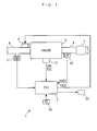
- FIG. 1 there is schematically shown the arrangement of a degradation determining system 1 according to a first embodiment of the present invention, and an internal combustion engine (hereinafter simply referred to as “the engine") 3 incorporating a LAF sensor 12 (exhaust gas sensor) to which is applied the degradation determining system 1.
- the degradation determining system 1 includes an ECU 2.
- the engine 3 is a straight type four-cylinder gasoline engine, for instance.
- An intake pipe 4 of the engine 3 has an intake manifold, not shown, into which are inserted injectors 5 (only one of which is shown) in a manner facing respective combustion chambers, not shown, of cylinders.
- Each injector 5 has its fuel injection time period TOUT (fuel injection amount) over which the injector 5 is open, controlled by a drive signal delivered from the ECU 2.
- the intake pipe 4 has an intake pipe absolute pressure sensor 11 inserted therein at a location upstream of the injector 5 and downstream of a throttle valve, not shown.
- the intake pipe absolute pressure sensor 11 is implemented e.g. by a semiconductor absolute pressure sensor for detecting an intake pipe absolute pressure PBA within the intake pipe 4 to deliver an electric signal indicative of the sensed intake pipe absolute pressure PBA to the ECU 2.
- the LAF sensor 12 and a three-way catalyst 7 are mounted in an exhaust pipe 6 (exhaust passage) of the engine 3 at respective locations, from upstream to downstream, in the mentioned order.
- the LAF sensor 12 detects the concentration of oxygen contained in exhaust gases linearly in a wide range of the air-fuel ratio ranging from a rich region to a lean region, to deliver an output KACT (output from an exhaust gas sensor) proportional to the sensed oxygen concentration to the ECU 2.
- the output KACT is expressed as an equivalent ratio proportional to the reciprocal of the air-fuel ratio.
- the three-way catalyst 7 is activated and reduces harmful substances (HC, CO and NO x ) in exhaust gases passing therethrough by oxidation-reduction catalytic actions thereof.
- the emission-reducing capability of the three-way catalyst 7 is maximized when the air-fuel ratio is equal to the stoichiometric air-fuel ratio, that is, when the value of the output KACT from the LAF sensor 12 assumes 1.0 (value of the equivalent ratio corresponding to the stoichiometric air-fuel ratio).
- the ECU 2 receives a CRK signal and a TDC signal, which are both pulse signals, delivered from a crank angle sensor 13 in accordance with rotation of a crankshaft, not shown, and an electric signal indicative of a speed VP of a vehicle, not shown, (hereinafter referred to as "the vehicle speed VP") delivered from a vehicle speed sensor 14.
- the crankshaft angle sensor 13 delivers the CRK signal whose pulse is generated whenever the crankshaft rotates through a predetermined angle (e.g. 30 degrees) to the ECU 2.
- the ECU 2. calculates a rotational speed NE of the engine 3 (hereinafter referred to as "the engine speed NE”) based on the CRK signal.
- the TDC signal indicates that each piston, not shown, in an associated cylinder is in a predetermined crank angle position immediately before the TDC position at the start of the intake stroke of the piston, and each pulse of the TDC signal is generated whenever the crankshaft rotates through a predetermined angle.
- the ECU 2 has a warning lamp 20 connected thereto.
- the ECU 2 determines, through execution of a degradation determining process, described hereinafter, that the LAF sensor 12 is degraded, the ECU 2 turns on the warning lamp 20 so as to notify the driver of the fact.
- the ECU 2 is implemented by a microcomputer including an I/O interface, a CPU, a RAM, and a ROM, none of which are shown.
- the ECU 2 determines operating conditions of the engine 3, based on the outputs from the aforementioned sensors 11 to 14, and in dependence on the determined operating conditions of the engine 3, calculates a fuel injection time period TOUT of each injector 5, on a cylinder-by-cylinder basis, according to control programs and data read from the ROM, data stored in the RAM, and the like. Then, the ECU 2 delivers a drive signal generated based on the fuel injection time period TOUT to the injector 5, to thereby control the air-fuel ratio of a mixture supplied to the engine 3.
- the ECU 2 executes the feedback (hereinafter abbreviated to "F/B") control of the air-fuel ratio such that the output KACT from the LAF sensor 12 is converged to a target air-fuel ratio KCMD. Further, the ECU 2 sets the target air-fuel ratio KCMD by searching a map, not shown, according to the engine speed NE and the intake pipe absolute pressure PBA. Furthermore, as described hereinafter, the ECU 2 carries out the degradation determining process for determining degradation of the LAF sensor 12, based on the output KACT from the LAF sensor 12, and the air-fuel ratio control process, referred to hereinafter, adapted to the degradation determining process during execution thereof. It should be noted that in the present embodiment, determining input-generating means, modulation output-generating means, control means, degradation determining means, a bandpass filter, cumulative value-generating means, and correction means are implemented by the ECU 2.
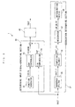
- the degradation determining system 1 is comprised of a determining input signal-generating section 30 for setting (generating) a predetermined coefficient, a fuel injection time period-calculating section 40 for calculating the fuel injection time period TOUT based on the predetermined coefficient, and a degradation determining section 31 for determining the degradation of the LAF sensor 12, all of which are implemented by the ECU 2.
- the determining input signal-generating section 30 includes a function generator 32 (determining input-generating means), a DSM controller 33 (modulation output-generating means), and a F/B-compensator 34 (correction means).
- the function generator 32 generates a determining input signal IDSIN (determining input) for determining the degradation of the LAF sensor 12, during execution of the degradation determining process, and outputs the signal to the DSM controller 33.
- the determining input signal IDSIN is of a sinusoidal wave set to have a predetermined frequency fid (e.g. 2 Hz: frequency of the determining input).
- the DSM controller 33 calculates (generates) a fuel reflection coefficient KIDDSM based on the determining input signal IDSIN generated by the function generator 32, using a control algorithm to which the ⁇ modulation algorithm is applied, during execution of the degradation determining process.
- the DSM controller 33 and the operation thereof for calculating the fuel reflection coefficient KIDDSM will be described in detail hereinafter.
- the F/B-compensator 34 calculates an F/B correction coefficient KAF.
- the F/B correction coefficient KAF is set to a value obtained by multiplying an observer feedback correction coefficient #nKLAF and a correction coefficient KFB by each other.
- the observer feedback correction coefficient #nKLAF is calculated by PID control, according to an actual air-fuel ratio estimated by an observer for each cylinder from the output KACT from the LAF sensor 12.
- the correction coefficient KFB is set to a value calculated by the PID control according to a deviation between the output KACT from the LAF sensor 12 and the target air-fuel ratio KCMD, or to a value obtained by multiplying the target air-fuel ratio KCMD by a coefficient calculated by a Self Tuning Regulator type adaptive controller, not shown, depending on the operating conditions of the engine 3.
- the fuel injection time period-calculating section 40 calculates the fuel injection time period TOUT using a value obtained by multiplying the fuel reflection coefficient KIDDSM and the F/B correction coefficient KAF, calculated as above, by each other, and the target air-fuel ratio KCMD, depending on the operating conditions of the engine 3 including the engine speed NE and the intake pipe absolute pressure PBA.
- the degradation determining section 31 includes a bandpass filter 35, a computing element 36, an integrator 37 (cumulative value-generating means), and a determination device 38 (degradation determining means).
- the bandpass filter 35 filters the output KACT from the LAF sensor 12 such that components of the output KACT from the LAF sensor 12 in a predetermined frequency band including the predetermined frequency fid of the determining input signal IDSIN described above are allowed to pass therethrough, to thereby generate a filtered value KACT_F (filtered output from the exhaust gas sensor).
- the bandpass filter 35 has gain characteristics and phase characteristics, as shown in FIG. 3. Its gain is set such it becomes equal to a value of 0dB when the frequency of the output KACT from the LAF sensor 12 is equal to the predetermined frequency fid.
- KACT_F a1 ⁇ KACT_F(k-1) + a2 ⁇ KACT_F(k-2) + a3 ⁇ KACT_F(k-3) + b0 ⁇ KACT(k) + b1 ⁇ KACT(k-1) + b2 ⁇ KACT(k-2) + b3 ⁇ KACT(k-3)
- a1, a2, a3, b0, b1, b2, and b3 represent predetermined filter coefficients, respectively.
- the computing element 36 calculates (generates) an amplitude absolute value KACT_FA (indicative of a state of changes in amplitude of the output from the exhaust gas sensor) which is the absolute value of the amplitude the filtered value KACT_F calculated as described above.
- the integrator 37 integrates the amplitude absolute value KACT_FA as described hereinafter, to thereby calculate (generate) a determining parameter LAF_DYLP (cumulative value).
- the determination device 38 determines the degradation of the LAF sensor 12 based on the determining parameter LAF_DYLP, as will be described hereinafter.
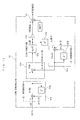
- FIG. 4 shows the construction of a control system in which a controller 41 having the ⁇ modulation algorithm applied thereto controls a controlled object 42.
- a deviation signal ⁇ (k) is generated by a differentiator 41a, as a deviation of a DSM output u(k-1) obtained by delaying the DSM output u(k) using a delay element 41b, from a reference input r(k).
- the integral of the deviation (hereinafter referred to as "a deviation integral value”) ⁇ (k) is generated by an integrator 41c, as a signal of the sum obtained by adding together the deviation signal ⁇ (k) and a deviation integral value ⁇ (k-1) obtained by delaying the deviation integral value ⁇ (k) using a delay element 41d.
- the DSM output u(k) (modulation output) is generated by a quantizer 41e (sign (signum) function), as a signal indicative of a sign determined based on the deviation integral value ⁇ (k).
- the DSM output u(k) thus generated is input to the controlled object 42, and an output signal y(k) is output from the controlled object 42 in response thereto.
- FIG. 5 shows results of a simulation of control by the above control system.
- the DSM output u(k) is generated as a rectangular signal
- the output signal y(k) different in amplitude from the reference input r(k), but identical in frequency to the same is output from the controlled object 42.
- the output signal y(k) has a waveform similar to that of the reference input r(k) as a whole.
- the ⁇ modulation algorithm is characterized in that the DSM output u(k) can be generated from the reference input r(k), as a value which when input to the controlled object 42, causes the output y(k) from the controlled object 42 to be generated as a signal different in amplitude from the reference input r(k), but identical in frequency and similar in waveform as a whole to the same.
- the characteristic of the ⁇ modulation algorithm lies in that the DSM output u(k) can be generated as a value which causes the reference input r(k) to be reproduced in the actual output y(k) from the controlled object 42.
- the DSM controller 33 by utilizing the above characteristic of the ⁇ modulation algorithm, generates the fuel reflection coefficient KIDDSM during executing of the degradation determining process for determining the degradation of the LAF sensor 12, such that the output KACT from the LAF sensor 12 is not changed according to unexpected changes in the air-fuel ratio. More specifically, the fuel reflection coefficient KIDDSM is calculated (generated) according to a value obtained by multiplying the DSM output u(k) by an amplitude-adjusting gain F, referred to hereinafter, whereby the fuel reflection coefficient KIDDSM is changed with a relatively large amplitude.
- the fuel injection time period TOUT as well which is calculated as described above according to the fuel reflection coefficient KIDDSM, can be changed with a relatively large amplitude, so that it is possible to make changes in the fuel injection time period TOUT, which can cause the unexpected changes in the air-fuel ratio, obscure or lost in changes in the fuel injection time period TOUT the range of which is controlled as described above.
- the air-fuel ratio control using the fuel reflection coefficient KIDDSM calculated as above that is, the air-fuel ratio control process adapted to the degradation determination is carried out.
- the determining input signal IDSIN generated by the function generator 32 described above is input as the reference signal r(k).
- a deviation signal ⁇ (k) is generated by a differentiator 33a as a deviation of a DSM output u(k-1) obtained by delaying a DSM output u(k) using a delay element 33b, from the reference signal r(k).
- an integrator 33c generates a deviation integral value ⁇ (k) as a signal of the sum obtained by adding together the deviation signal ⁇ (k) and a deviation integral value ⁇ (k-1) obtained by delaying the deviation integral value ⁇ (k) using a delay element 33d, whereafter a quantizer 33e (sign function) generates the DSM output u(k) as a value indicative of a sign determined based on the deviation integral value ⁇ (k).
- an amplifier 33f generates an amplified DSM output IDDSM(k) as a value obtained by amplifying the DSM output u(k) by the amplitude-adjusting gain F, and then an adder 33g adds together the amplified DSM output IDDSM(k) and a predetermined offset value IDOFT (predetermined value) to thereby generate a fuel reflection coefficient KIDDSM(k).
- the value of the amplitude-adjusting gain F is set to a predetermined value (e.g. 0.1 A/F).
- the predetermined offset value IDOFT is set through experiments such that the output KACT from the LAF sensor 12 becomes closer to the target air-fuel ratio KCMD, when the air-fuel ratio is controlled using the fuel injection time period TOUT calculated according to the fuel reflection coefficient KIDDSM.
- step 1 in FIG. 1, shown as "S1"; which rule applies similarly in the following description, it is determined whether or not a degradation determination completion flag F_LODONE is set to 1. If the answer to this question is affirmative (YES), i.e. if the degradation determining process has already been completed, the present program is immediately terminated.
- step 2 it is determined whether or not the LAF sensor 12 has been activated and then to a step 3 wherein it is determined whether or not determining conditions for determining the degradation of the LAF sensor 12 are satisfied.
- a predetermined value e.g. 0.4 V
- the degradation determining system 1 calculates the fuel reflection coefficient KIDDSM, as described above, and thereby changes the fuel injection time period TOUT with a relatively large amplitude, to cause changes in the air-fuel ratio of the mixture supplied to the engine with a relatively large amplitude. Then, the degradation determining system 1 determines whether or not the output KACT from the LAF sensor 12 indicates a state of changes corresponding to the changes in the air-fuel ratio caused by the fuel reflection coefficient KIDDSM, to thereby determine the degradation of the LAF sensor 12.
- the fuel reflection coefficient KIDDSM is set to 1.0 in a step 4, a timer count TM_KFD of a downcount standby timer is set to a predetermined standby time period TM_KACTFD (e.g. 0.5 seconds; predetermined time period) in a step 5, and a timer count TM_LOP of a determining timer is set to a predetermined determining time period TM_LOPRD (e.g. 2.5 seconds) in a step 6.
- the degradation determination completion flag F_LODONE is set to 0, followed by terminating the present program.
- the fuel reflection coefficient KIDDSM is set to 1.0.
- the fuel injection time period TOUT is calculated using the F/B correction coefficient KAF and the target air-fuel ratio KCMD, depending on the operating conditions of the engine 3, whereby the air-fuel ratio is controlled such that the output KACT from the LAF sensor 12 becomes equal to the target air-fuel ratio KCMD.
- a fuel reflection coefficient KIDDSM-calculating process for calculating the fuel reflection coefficient KIDDSM is carried out in a step 8.
- the fuel reflection coefficient KIDDSM is calculated (generated) by the DSM controller 33 based on the determining input signal IDSIN generated by the function generator 32.
- FIG. 8 is a flowchart showing a subroutine for carrying out the fuel reflection coefficient KIDDSM-calculating process.
- a step 24 the sum [DSMSIGMA(k-1) + DSMDELTA] obtained by adding together the immediately preceding value DSMSIGMA(k-1) of the deviation integral value and the deviation signal value DSMDELTA is set to the present value DSMSIGMA(k) of the deviation integral value.
- This process corresponds to the above-mentioned equation (6).
- the program proceeds to steps 25 to 27, wherein if the present value DSMSIGMA(k) of the deviation integral value calculated in the step 24 is equal to or larger than 0 (S25), the present value DSMSGNS(k) of the DSM output is set to 1.0 (S26), whereas if the present value DSMSIGMA(k) is smaller than 0, the present value DSMSGNS(k) of the DSM output is set to -1.0 (S27).
- the process carried out in the steps 25 to 27 corresponds to the above-mentioned equation (7).
- a value obtained by multiplying the amplitude-adjusting gain F and the present value DSMSGNS(k) of the DSM output set in the step 26 or 27 by each other is set to the amplified DSM output IDDSM.
- This process corresponds to the above-mentioned equation (8).
- a step 29 the sum obtained by adding together the amplified DSM output IDDSM calculated in the step 28 and the offset value IDOFT is set to the fuel reflection coefficient KIDDSM, followed by terminating the present program.
- This process corresponds to the above-mentioned equation (9).
- the air-fuel ratio is changed with a relatively large amplitude by carrying out the air-fuel ratio control using the fuel reflection coefficient KIDDSM calculated by the KIDDSM-calculating process, that is, the air-fuel ratio control process adapted to the degradation determination.
- the filtered value KACT_F is calculated.
- the filtered value KACT_F is calculated using the above-mentioned equation (1), as a value obtained by extracting only components contained in the predetermined frequency band including the predetermined frequency fid of the determining input signal IDSIN, from the output KACT from the LAF sensor 12.
- the amplitude absolute value KACT_FA is calculated based on the filtered value KACT_F calculated in the step 9, and it is determined in a step 11 whether or not the timer count TM_KFD of the standby timer, set in the step 5, is equal to 0. If the answer to this question is negative (NO), i.e. if the predetermined standby time period TM_KACTFD has not elapsed after the start of the air-fuel ratio control process adapted to the degradation determination, the step 7 is executed, followed by terminating the present program without determining the degradation of the LAF sensor 12.
- the degradation of the LAF sensor 12 is not executed. This is for the following reason: There is a delay of a certain time period before the output KACT from the LAF sensor 12 indicates a value corresponding to a mixture supplied to a cylinder of the engine 3.
- the standby time period after the start of the air-fuel ratio control process which is set by the predetermined standby time period TM_KACTFD, also plays the role of causing the degradation determining system to wait for the filtered value KACT_F to be made stable, since attenuation of the initial response of the filtered value KACT_F is awaited thereby.
- the determining parameter LAF_DLYP is calculated as the sum obtained by adding together the immediately preceding value thereof and the amplitude absolute value KACT_FA. If the present loop is a first loop to be executed immediately after the start of the present program, the determining parameter LAF_DLYP is set to the present amplitude absolute value KACT_FA.
- step 13 it is determined whether or not the timer count TM_LOP of the determining timer set in the step 6 is equal to 0. If the answer to this question is negative (NO), the step 7 is carried out, followed by terminating the present program without determining the degradation of the LAF sensor 12.
- TM_LOP 0 holds, which means that calculation of the determining parameter LAF_DLYP is repeatedly carried out a plurality of times corresponding to the predetermined determining time period TM_LOPRD from the start of the air-fuel ratio control process adapted to the degradation determination, it is determined in a step 14 whether or not the present determining parameter LAF_DLYP is equal to or larger than a predetermined reference value LAF_DLYP_OK (e.g. 0.001).
- the determining parameter LAF_DLYP is set to a value obtained by integrating the amplitude absolute value KACT_FA calculated whenever the present program is carried out, over a time period from the start of the air-fuel ratio control until the lapse of the predetermined determining time period TM_LOPRD.
- the degradation determination completion flag F_LODONE is set to 1 in a step 16, followed by terminating the present program.
- the degradation flag F_LAFOBD is held at 0.
- FIGS. 9 and 10 show respective examples of operations executed by the degradation determining process, when the LAF sensor 12 is normally operating, and when the LAF sensor 12 is degraded. It should be noted that in these examples, the predetermined offset value IDOFT is set to a value of 1.0 (corresponding to the equivalent ratio of the stoichiometric air-fuel ratio). Further, in FIGS.
- time t1 designates a time point the air-fuel ratio control process adapted to the degradation determination starts to be executed
- t2 designates a time point the determining parameter LAF_DLYP starts to be calculated when the standby time period TM_KACTFD has elapsed after the start of the air-fuel ratio control process adapted to the degradation determination
- t3 designates a time point the predetermined determining time period TM_LOPRD has elapsed. Furthermore, during a time period between the time points t1 and t3, the F/B correction coefficient KAF is held at 1.0.
- the fuel reflection coefficient KIDDSM is changed with respect to 1 with a relatively large amplitude corresponding to the amplitude-adjusting gain F, toward the positive side and the negative side in a rectangular waveform. Accordingly, as shown in FIG. 9, when the LAF sensor 12 is normally operating, the output KACT from the LAF sensor 12 undergoes clear waveform-like changes toward the rich side and the lean side in a manner corresponding to changes in the air-fuel ratio occurring with a relatively large amplitude according to the above fuel reflection coefficient KIDDSM.
- the filtered value KACT_F obtained by filtering the output KACT from the LAF sensor 12 with the bandpass filter 35 changes with respect to a value of 0 toward the positive side and the negative side in a smooth and clear waveform, by elimination of noise except for components in the predetermined frequency band including the predetermined frequency fid.
- the amplitude of the filtered value KACT_F increases with the lapse of time.
- the amplitude absolute value KACT_FA which is the absolute value of the amplitude of the filtered value KACT_F, has the same tendency as that of the filtered value KACT_F, and undergoes changes with smooth, clear and large amplitudes.
- the determining parameter LAF_DLYP which is the cumulative value of the amplitude absolute value KACT_FA, increases at a relatively large rate with the lapse of time. Therefore, it is possible to determine that the LAF sensor 12 is normally operating, when the determining parameter LAF_DLYP is equal to or larger than the predetermined reference value LAF_DLYP_OK.
- the LAF sensor 12 when the LAF sensor 12 is degraded, as shown in FIG. 10, even if the air-fuel ratio is changed with a relatively large amplitude by the fuel reflection coefficient KIDDSM after the start of the air-fuel ratio control process adapted to the degradation determination (after t1), the output KACT from the LAF sensor 12 with respect to the changes in the air-fuel ratio undergoes smaller changes and fails to exhibit clear waveform-like changes compared with the case in which the LAF sensor 12 is normally operating. Therefore, the amplitudes of the filtered value KACT_F and the amplitude absolute value KACT_FA are both very small. This also causes the determining parameter LAF_DLYP to increase at a very small rate. Therefore, when the determining parameter LAF_DLYP is smaller than the determination value LAF_DLYP_OK, it is possible to determine that the LAF sensor 12 is degraded.
- the fuel injection time period TOUT is changed with a larger amplitude than a range of changes in the fuel injection time period TOUT causing unexpected changes in the air-fuel ratio, using the fuel reflection coefficient KIDDSM calculated by utilizing the above-described characteristics of the ⁇ modulation algorithm.
- This makes it possible to suppress adverse influence of noise caused by the unexpected changes in the air-fuel ratio on the output KACT from the LAF sensor 12. Therefore, it is possible to determine the degradation of the LAF sensor 12 based on the output KACT delivered when the adverse influence of noise thereon is suppressed, and thereby enhance accuracy of the determination of degradation of the LAF sensor 12.
- the determination of degradation of the sensor using the determining parameter LAF_DLYP can be carried out based on the output KACT from the LAF sensor 12 delivered after the air-fuel ratio has been positively controlled by the air-fuel ratio control process adapted to the degradation determination. This makes it possible to further enhance the accuracy of the determination of degradation of the LAF sensor 12.
- the filtered value KACT_F is calculated as a value obtained by filtering the output KACT from the LAF sensor 12 such that components thereof corresponding to the predetermined frequency band including the predetermined frequency fid of the determining input signal IDSIN are passed, and the determining parameter LAF_DLYP is calculated base on the filtered value KACT_F. Therefore, noise which can be contained in the output KACT from the LAF sensor 12 before filtering can be eliminated to thereby further enhance the accuracy of the determination of degradation of the LAF sensor 12.
- the determining parameter LAF_DLYP is calculated based on the filtered value KACT_F as the cumulative value of the amplitude absolute value KACT_FA of the filtered value KACT_F, it is possible to eliminate the adverse influence of noise contained in the output KACT from the LAF sensor 12, to thereby further enhance the accuracy of the determination of degradation of the LAF sensor 12.
- the fuel injection time period TOUT is calculated based on the predetermined offset value IDOFT such that the output KACT from the LAF sensor 12 becomes closer to the target air-fuel ratio KCMD. This makes it possible to maintain the excellent emission-reducing capability of the three-way catalyst 7 to thereby maintain excellent exhaust emission characteristics. Furthermore, during execution of the degradation determining process, the fuel injection time period TOUT is calculated using the F/B correction coefficient KAF, whereby the F/B control of the air-fuel ratio is carried out in response to the output KACT from the LAF sensor 12. Therefore, the output KACT from the LAF sensor 12 can be always made closer to the target air-fuel ratio KCMD to thereby maintain more excellent exhaust emission characteristics.
- the present embodiment is distinguished from the first embodiment only in a method of determining the degradation of the LAF sensor 12 at a final stage of the degradation determining process. More specifically, as described hereinbefore, in the first embodiment, the degradation of the LAF sensor 12 is determined using the determining parameter LAF_DLYP, which is the cumulative value of the amplitude absolute value KACT_FA. However, in the present embodiment, the degradation of the LAF sensor 12 is determined based on the number of times that the amplitude absolute value KACT_FA has exceeded a predetermined threshold value KACTREF.
- FIG. 11 is a flowchart showing a degradation determining process according to the present embodiment. In FIG.
- steps similar to those of the degradation determining process according to the first embodiment are designated by identical step numbers. Further, as is apparent from FIG. 11, the degradation determining process according to the present embodiment is different from that of the first embodiment shown in FIG. 7, in steps subsequent to the step 11, so that in the following, these steps will be described in detail with reference to FIG. 11.
- step 31 If the answer to this question is affirmative (YES), the count CNT of a determination counter is incremented in a step 31, followed by the program proceeding to a step 32. On the other hand, if the answer to the above question is negative (NO), i.e. if KACT_FA ⁇ KACTREF holds, the step 31 is skipped over to the step 32.
- step 32 it is determined whether or not the timer count TM_LOP of the determining timer set in the step 6 is equal to 0. If the answer to the above question is negative (NO), the step 7 is executed, followed by terminating the present program without determining the degradation of the LAF sensor 12.
- step 32 determines whether or not the count CNT of the determination counter is equal to or larger than a predetermined value CNTREF. If the answer to this question is negative (NO), i.e.
- the LAF sensor 12 is determined to be degraded for the following reason: As described above, when the LAF sensor 12 is normally operating, the amplitude of the filtered value KACT_F is controlled to be large, whereas when the LAF sensor 12 is degraded, the amplitude of the filtered value KACT_F remains small, and the amplitude absolute value KACT_FA as well has the same tendency as that of the filtered value KACT_F. Therefore, the degradation of the LAF sensor 12 can be determined based on the number of times that the amplitude absolute value KACT_FA has exceeded the predetermined threshold value KACTREF.
- the LAF sensor 12 when the number of times that the amplitude absolute value KACT_FA, which is the absolute value of the amplitude of the filtered value KACT_F, has become equal to or larger than the predetermined threshold value KACTREF has reached the predetermined value CNTREF, it is judged that the LAF sensor 12 is normally operating. Therefore, it is possible to determine the degradation of the LAF sensor 12 while eliminating adverse influence of noise caused by unexpected changes in the air-fuel ratio on the output KACT from the LAF sensor 12, and therefore enhance accuracy of determination of the LAF sensor 12. As a result, it is possible to obtain the same advantageous effects as provided by the degradation determining system 1 according to the first embodiment.
- the present embodiment is distinguished from the first embodiment only in that an SDM controller 51 (modulation output-generating means) is employed instead of the DSM controller 33.
- the SDM controller 51 calculates the fuel reflection coefficient KIDDSM based on the determining input signal IDSIN, by utilizing a control algorithm having the ⁇ modulation algorithm applied thereto.
- the determining input signal IDSIN is input to the SDM controller 51 as the reference signal r(k).
- an integrator 51a generates a reference signal integral value ⁇ r(k) as a signal of the sum obtained by adding together a reference signal integral value ⁇ r(k-1) obtained by delaying a reference signal integral value ⁇ r(k) using a delay element 51b and the reference signal r(k).
- an integrator 51c generates an SDM output integral value ⁇ u s (k) as a signal of the sum obtained by adding together an SDM output integral value ⁇ u s (k-1) obtained by delaying the SDM output integral value ⁇ u s (k) using a delay element 51d and an SDM output u s (k-1) obtained by delaying a SDM output u s (k) using a delay element 51e.
- a differentiator 51f generates a deviation signal ⁇ (k) indicative of a deviation between the reference signal integral value ⁇ r(k) and the SDM output integral value ⁇ u s (k).
- a quantizer 51g (sign function) generates the SDM output u s (k) (modulation output) as a value indicative of a sign determined based on the deviation signal ⁇ (k). Further, an amplifier 51h generates an amplified SDM output IDDSM(k) as a value obtained by amplifying the SDM output u s (k) by the amplitude-adjusting gain F, and then an adder 51i generates a fuel reflection coefficient KIDDSM(k) as a value obtained by adding together the amplified SDM output IDDSM(k) and the predetermined offset value IDOFT.
- the value of the amplitude-adjusting gain F is set to a predetermined value (e.g. 0.1 A/F).
- the predetermined offset value IDOFT is set through experiments such that the output KACT from the LAF sensor 12 becomes closer to the target air-fuel ratio KCMD, when the air-fuel ratio is controlled using the fuel injection time period TOUT calculated using the fuel reflection coefficient KIDDSM.
- the above control algorithm used by the SDM controller 51 that is, the ⁇ modulation algorithm is characterized, similarly to the ⁇ modulation algorithm, in that the SDM output u s (k) can be generated as a value which when input to a controlled object, causes the reference signal r(k) to be reproduced in the output from the controlled object. More specifically, the SDM controller 51 is characterized in that it can generate a fuel reflection coefficient KIDDSM which is similar to that generated by the DSM controller 33 described above. Therefore, according to the present embodiment, it is possible to obtain the same advantageous effects as provided by the degradation determining system 1 according to the first embodiment. It should be noted that although not shown, the SDM controller 51 calculates the fuel reflection coefficient KIDDSM substantially similarly to the case of the DSM controller 33.
- the present embodiment is distinguished from the first embodiment only in that a DM controller 61 (modulation output-generating means) is employed instead of the DSM controller 33.
- the DM controller 61 calculates the fuel reflection coefficient KIDDSM based on the determining input signal IDSIN, using a control algorithm to which a ⁇ modulation algorithm is applied.
- the determining input signal IDSIN is input to the DM controller 61 as the reference signal r(k).
- an integrator 61a generates a DM output integral value ⁇ u d (k) as a signal of the sum obtained by adding together a DM output integral value ⁇ u d (k-1) obtained by delaying a DM output integral value ⁇ u d (k) using a delay element 61b and a DM output u d (k-1) obtained by delaying a DM output u d (k) using a delay element 61c.
- a differentiator 61d generates a deviation signal ⁇ (k) indicative of a deviation between the reference signal r(k) and the DM output integral value ⁇ u d (k).
- a quantizer 61e (sign function) generates a DM output u d (k) (modulation output) as a value indicative of a sign determined based on the deviation signal ⁇ (k). Further, an amplifier 61f generates an amplified DM output IDDSM(k) as a value obtained by amplifying the DM output u d (k) by the amplitude-adjusting gain F, and then an adder 61g generates a fuel reflection coefficient KIDDSM(k) as a value obtained by adding together the amplified DM output IDDSM(k) and the predetermined offset value IDOFT.
- the value of the amplitude-adjusting gain F is set to a predetermined value (e.g. 0.1 A/F).
- the predetermined offset value IDOFT is set through experiments such that the output KACT from the LAF sensor 12 becomes closer to the target air-fuel ratio KCMD, when the air-fuel ratio is controlled by the fuel injection time period TOUT calculated using the fuel reflection coefficient KIDDSM.
- the above control algorithm employed by the DM controller 61 that is, the ⁇ modulation algorithm is characterized, similarly to the ⁇ modulation algorithm, in that the DM output u d (k) can be generated as a value which when input to a controlled object, causes the reference signal r(k) to be reproduced in the output from the controlled object. More specifically, the DM controller 61 is characterized in that it can generate a fuel reflection coefficient KIDDSM which is similar to those generated by the DSM controller 33 and the SDM controller 51. Therefore, according to the present embodiment, it is possible to obtain the same advantageous effects as provided by the degradation determining system 1 according to the first embodiment. It should be noted that although not shown, the DM controller 61 calculates the fuel reflection coefficient KIDDSM substantially similarly to the case of the DSM controller 33.
- the present invention is not necessarily limited to the embodiments described above, but can be practiced in various forms.
- the degradation of the LAF sensor 12 is determined, this is not limitative, but there may be determined degradation of another type of a sensor that outputs a signal indicative of the sensed concentration of oxygen contained in exhaust gases, such as an oxygen concentration sensor which has a characteristic that its output sharply changes when the air-fuel ratio of the exhaust gases changes across the stoichiometric air-fuel ratio, an NOx sensor that detects the concentration of NOx contained in exhaust gases, and an HC sensor that detects the concentration of HC contained in exhaust gases.
- an oxygen concentration sensor which has a characteristic that its output sharply changes when the air-fuel ratio of the exhaust gases changes across the stoichiometric air-fuel ratio
- an NOx sensor that detects the concentration of NOx contained in exhaust gases
- an HC sensor that detects the concentration of HC contained in exhaust gases.
- the determining input signal-generating section 30, and the degradation determining section 31 may be implemented by electric circuits without executing software-based processing based on programs as in the above described embodiments.
- the LAF sensor 12 is disposed at a location upstream of the catalytic converter 7, this is not limitative, but it goes without saying that the LAF sensor 12 may be disposed at a location downstream of the catalytic converter 7.
- a degradation determining system for an exhaust gas sensor which, even when unexpected changes occur in the air-fuel ratio during execution of air-fuel ratio control, can determine degradation of the sensor by suppressing adverse influence of noise caused by the changes on the output from the sensor, to thereby enhance the accuracy of the degradation determination.
- a determining input signal IDSIN for determining the degradation of the sensor is generated, and a modulation output ( u(k), DSMSGNS(k), u s (k), or u d (k)) is generated by modulating the determining input signal IDSIN by using any one of the ⁇ modulation algorithm, the ⁇ modulation algorithm, and the ⁇ modulation algorithm.
- Degradation of the sensor is determined based on the output KACT delivered from the sensor when the fuel injection amount is controlled based on the generated modulation output.
Landscapes
- Engineering & Computer Science (AREA)
- Chemical & Material Sciences (AREA)
- Combustion & Propulsion (AREA)
- Mechanical Engineering (AREA)
- General Engineering & Computer Science (AREA)
- Electrical Control Of Air Or Fuel Supplied To Internal-Combustion Engine (AREA)
- Combined Controls Of Internal Combustion Engines (AREA)
- Exhaust Gas After Treatment (AREA)
Applications Claiming Priority (2)
| Application Number | Priority Date | Filing Date | Title |
|---|---|---|---|
| JP2002325606 | 2002-11-08 | ||
| JP2002325606A JP4030010B2 (ja) | 2002-11-08 | 2002-11-08 | 排ガスセンサの劣化判定装置 |
Publications (3)
| Publication Number | Publication Date |
|---|---|
| EP1418326A2 true EP1418326A2 (de) | 2004-05-12 |
| EP1418326A3 EP1418326A3 (de) | 2009-12-30 |
| EP1418326B1 EP1418326B1 (de) | 2012-07-25 |
Family
ID=32105507
Family Applications (1)
| Application Number | Title | Priority Date | Filing Date |
|---|---|---|---|
| EP03025674A Expired - Lifetime EP1418326B1 (de) | 2002-11-08 | 2003-11-07 | Verfahren und System zur Bestimmung des Verschlechterungsverhaltens eines Abgassensors |
Country Status (3)
| Country | Link |
|---|---|
| US (1) | US6792928B2 (de) |
| EP (1) | EP1418326B1 (de) |
| JP (1) | JP4030010B2 (de) |
Cited By (1)
| Publication number | Priority date | Publication date | Assignee | Title |
|---|---|---|---|---|
| EP1696287A1 (de) * | 2005-02-23 | 2006-08-30 | HONDA MOTOR CO., Ltd. | Steuervorrichtung |
Families Citing this family (9)
| Publication number | Priority date | Publication date | Assignee | Title |
|---|---|---|---|---|
| DE102004046874A1 (de) * | 2004-09-28 | 2006-04-13 | Robert Bosch Gmbh | Verfahren zum Betreiben eines Verwaltungssystems von Funktionsmodulen |
| DE102005029137B3 (de) * | 2005-06-23 | 2007-02-15 | Dr.Ing.H.C. F. Porsche Ag | Verfahren und Steuergerät zur Diagnose eines Gaswechsel-Ventilhub-Verstellsystems eines Verbrennungsmotors |
| JP2007064182A (ja) * | 2005-09-02 | 2007-03-15 | Toyota Motor Corp | 排気浄化装置 |
| FR2906312B1 (fr) * | 2006-09-27 | 2016-04-15 | Bosch Gmbh Robert | Procede de diagnostic d'un capteur de gaz d'echappement equipant un moteur a combustion interne et dispositif pour sa mise en oeuvre. |
| DE102008001213A1 (de) * | 2008-04-16 | 2009-10-22 | Robert Bosch Gmbh | Verfahren und Vorrichtung zur Diagnose der Dynamik eines Abgassensors |
| BR112012014974B1 (pt) * | 2009-12-16 | 2020-02-18 | Cummins Filtration Ip, Inc. | APARATO E MÉTODO PARA DIAGNOSTICAR UM SENSOR DE NOx |
| CN104380356B (zh) * | 2012-01-31 | 2017-05-03 | 卡明斯散发控制技术公司 | 传感器和传感器接口系统 |
| JP5883140B2 (ja) * | 2012-07-17 | 2016-03-09 | 本田技研工業株式会社 | 内燃機関の制御装置 |
| US9388728B2 (en) | 2013-06-10 | 2016-07-12 | Cummins Emission Solutions, Inc. | Systems and methods for NOx sensor diagnostics |
Family Cites Families (11)
| Publication number | Priority date | Publication date | Assignee | Title |
|---|---|---|---|---|
| US5363091A (en) * | 1991-08-07 | 1994-11-08 | Ford Motor Company | Catalyst monitoring using ego sensors |
| JP2827719B2 (ja) * | 1992-07-16 | 1998-11-25 | 三菱自動車工業株式会社 | O2 センサの故障判定方法 |
| US5325711A (en) * | 1993-07-06 | 1994-07-05 | Ford Motor Company | Air-fuel modulation for oxygen sensor monitoring |
| US5370101A (en) * | 1993-10-04 | 1994-12-06 | Ford Motor Company | Fuel controller with oxygen sensor monitoring and offset correction |
| US5758494A (en) * | 1997-01-16 | 1998-06-02 | Ford Global Technologies, Inc. | System and method for adaptive switch determination of exhaust gas sensors |
| US6370935B1 (en) * | 1998-10-16 | 2002-04-16 | Cummins, Inc. | On-line self-calibration of mass airflow sensors in reciprocating engines |
| US6539704B1 (en) * | 2000-03-17 | 2003-04-01 | Ford Global Technologies, Inc. | Method for improved vehicle performance |
| US6308697B1 (en) * | 2000-03-17 | 2001-10-30 | Ford Global Technologies, Inc. | Method for improved air-fuel ratio control in engines |
| US6564543B1 (en) * | 2001-04-07 | 2003-05-20 | Ford Global Technologies, Llc | System and method for monitoring a conditioning catalyst |
| JP2003193898A (ja) * | 2001-12-25 | 2003-07-09 | Honda Motor Co Ltd | 内燃機関の排気ガス浄化装置の劣化判別装置 |
| US6568177B1 (en) * | 2002-06-04 | 2003-05-27 | Ford Global Technologies, Llc | Method for rapid catalyst heating |
-
2002
- 2002-11-08 JP JP2002325606A patent/JP4030010B2/ja not_active Expired - Fee Related
-
2003
- 2003-11-07 EP EP03025674A patent/EP1418326B1/de not_active Expired - Lifetime
- 2003-11-07 US US10/702,429 patent/US6792928B2/en not_active Expired - Lifetime
Cited By (2)
| Publication number | Priority date | Publication date | Assignee | Title |
|---|---|---|---|---|
| EP1696287A1 (de) * | 2005-02-23 | 2006-08-30 | HONDA MOTOR CO., Ltd. | Steuervorrichtung |
| US7181330B2 (en) | 2005-02-23 | 2007-02-20 | Honda Motor Co., Ltd. | Control apparatus |
Also Published As
| Publication number | Publication date |
|---|---|
| EP1418326A3 (de) | 2009-12-30 |
| US6792928B2 (en) | 2004-09-21 |
| JP4030010B2 (ja) | 2008-01-09 |
| US20040094138A1 (en) | 2004-05-20 |
| JP2004162530A (ja) | 2004-06-10 |
| EP1418326B1 (de) | 2012-07-25 |
Similar Documents
| Publication | Publication Date | Title |
|---|---|---|
| US7021300B2 (en) | Diagnostic apparatus for an exhaust gas sensor | |
| US6985809B2 (en) | Control apparatus, control method, and engine control unit | |
| US7647157B2 (en) | Control device, control method, control unit, and engine control unit | |
| JP2893308B2 (ja) | 内燃機関の空燃比制御装置 | |
| US6195988B1 (en) | Air-fuel ratio control system for internal combustion engine | |
| JP4366701B2 (ja) | 内燃機関の空燃比制御装置 | |
| US6868326B2 (en) | Control apparatus, control method, control unit, and engine control unit | |
| EP1426594A2 (de) | Steuervorrichtung und Steuerverfahren | |
| JP2008157133A (ja) | 内燃機関の空燃比制御装置 | |
| US7720595B2 (en) | Abnormality diagnostic device for air-fuel ratio sensor, and control method for the device | |
| EP2063090A1 (de) | Steuervorrichtung für einen Verbrennungsmotor | |
| EP1418326B1 (de) | Verfahren und System zur Bestimmung des Verschlechterungsverhaltens eines Abgassensors | |
| JP2009115012A (ja) | 内燃機関の空燃比制御装置 | |
| US7059115B2 (en) | Air/fuel ratio control apparatus and method for internal combustion engine and engine control unit | |
| US6856891B2 (en) | Control apparatus, control method and engine control unit | |
| JP6316471B1 (ja) | エンジン制御装置およびエンジン制御方法 | |
| JP5271405B2 (ja) | 内燃機関の空燃比制御装置 | |
| JP5543852B2 (ja) | 内燃機関の空燃比制御装置 | |
| JP2006112274A (ja) | 内燃機関の空燃比制御装置 | |
| JP5297509B2 (ja) | 内燃機関の空燃比制御装置 | |
| JP4269281B2 (ja) | 内燃機関の空燃比制御装置 | |
| JP2002227689A (ja) | 内燃機関の空燃比制御装置 | |
| US9057337B2 (en) | Air-fuel ratio control system for internal combustion engine | |
| JP5342618B2 (ja) | 内燃機関の空燃比制御装置 | |
| US8726637B2 (en) | Air-fuel ratio control system for internal combustion engine |
Legal Events
| Date | Code | Title | Description |
|---|---|---|---|
| PUAI | Public reference made under article 153(3) epc to a published international application that has entered the european phase |
Free format text: ORIGINAL CODE: 0009012 |
|
| AK | Designated contracting states |
Kind code of ref document: A2 Designated state(s): AT BE BG CH CY CZ DE DK EE ES FI FR GB GR HU IE IT LI LU MC NL PT RO SE SI SK TR |
|
| AX | Request for extension of the european patent |
Extension state: AL LT LV MK |
|
| PUAL | Search report despatched |
Free format text: ORIGINAL CODE: 0009013 |
|
| AK | Designated contracting states |
Kind code of ref document: A3 Designated state(s): AT BE BG CH CY CZ DE DK EE ES FI FR GB GR HU IE IT LI LU MC NL PT RO SE SI SK TR |
|
| AX | Request for extension of the european patent |
Extension state: AL LT LV MK |
|
| 17P | Request for examination filed |
Effective date: 20100208 |
|
| 17Q | First examination report despatched |
Effective date: 20100504 |
|
| AKX | Designation fees paid |
Designated state(s): DE GB |
|
| GRAP | Despatch of communication of intention to grant a patent |
Free format text: ORIGINAL CODE: EPIDOSNIGR1 |
|
| GRAS | Grant fee paid |
Free format text: ORIGINAL CODE: EPIDOSNIGR3 |
|
| GRAA | (expected) grant |
Free format text: ORIGINAL CODE: 0009210 |
|
| AK | Designated contracting states |
Kind code of ref document: B1 Designated state(s): DE GB |
|
| REG | Reference to a national code |
Ref country code: GB Ref legal event code: FG4D |
|
| REG | Reference to a national code |
Ref country code: DE Ref legal event code: R096 Ref document number: 60341599 Country of ref document: DE Effective date: 20120920 |
|
| PGFP | Annual fee paid to national office [announced via postgrant information from national office to epo] |
Ref country code: GB Payment date: 20121107 Year of fee payment: 10 |
|
| PLBE | No opposition filed within time limit |
Free format text: ORIGINAL CODE: 0009261 |
|
| STAA | Information on the status of an ep patent application or granted ep patent |
Free format text: STATUS: NO OPPOSITION FILED WITHIN TIME LIMIT |
|
| 26N | No opposition filed |
Effective date: 20130426 |
|
| REG | Reference to a national code |
Ref country code: DE Ref legal event code: R084 Ref document number: 60341599 Country of ref document: DE |
|
| REG | Reference to a national code |
Ref country code: DE Ref legal event code: R097 Ref document number: 60341599 Country of ref document: DE Effective date: 20130426 |
|
| REG | Reference to a national code |
Ref country code: DE Ref legal event code: R084 Ref document number: 60341599 Country of ref document: DE Effective date: 20130802 |
|
| PGFP | Annual fee paid to national office [announced via postgrant information from national office to epo] |
Ref country code: DE Payment date: 20131030 Year of fee payment: 11 |
|
| GBPC | Gb: european patent ceased through non-payment of renewal fee |
Effective date: 20131107 |
|
| PG25 | Lapsed in a contracting state [announced via postgrant information from national office to epo] |
Ref country code: GB Free format text: LAPSE BECAUSE OF NON-PAYMENT OF DUE FEES Effective date: 20131107 |
|
| REG | Reference to a national code |
Ref country code: DE Ref legal event code: R119 Ref document number: 60341599 Country of ref document: DE |
|
| PG25 | Lapsed in a contracting state [announced via postgrant information from national office to epo] |
Ref country code: DE Free format text: LAPSE BECAUSE OF NON-PAYMENT OF DUE FEES Effective date: 20150602 |