EP1418332A2 - Système d'alimentation de carburant pour un moteur LPG - Google Patents
Système d'alimentation de carburant pour un moteur LPG Download PDFInfo
- Publication number
- EP1418332A2 EP1418332A2 EP03025313A EP03025313A EP1418332A2 EP 1418332 A2 EP1418332 A2 EP 1418332A2 EP 03025313 A EP03025313 A EP 03025313A EP 03025313 A EP03025313 A EP 03025313A EP 1418332 A2 EP1418332 A2 EP 1418332A2
- Authority
- EP
- European Patent Office
- Prior art keywords
- evaporator
- heating device
- fuel system
- propellant gas
- combustion engine
- Prior art date
- Legal status (The legal status is an assumption and is not a legal conclusion. Google has not performed a legal analysis and makes no representation as to the accuracy of the status listed.)
- Granted
Links
Images
Classifications
-
- F—MECHANICAL ENGINEERING; LIGHTING; HEATING; WEAPONS; BLASTING
- F02—COMBUSTION ENGINES; HOT-GAS OR COMBUSTION-PRODUCT ENGINE PLANTS
- F02M—SUPPLYING COMBUSTION ENGINES IN GENERAL WITH COMBUSTIBLE MIXTURES OR CONSTITUENTS THEREOF
- F02M21/00—Apparatus for supplying engines with non-liquid fuels, e.g. gaseous fuels stored in liquid form
- F02M21/02—Apparatus for supplying engines with non-liquid fuels, e.g. gaseous fuels stored in liquid form for gaseous fuels
- F02M21/06—Apparatus for de-liquefying, e.g. by heating
-
- F—MECHANICAL ENGINEERING; LIGHTING; HEATING; WEAPONS; BLASTING
- F02—COMBUSTION ENGINES; HOT-GAS OR COMBUSTION-PRODUCT ENGINE PLANTS
- F02D—CONTROLLING COMBUSTION ENGINES
- F02D19/00—Controlling engines characterised by their use of non-liquid fuels, pluralities of fuels, or non-fuel substances added to the combustible mixtures
- F02D19/02—Controlling engines characterised by their use of non-liquid fuels, pluralities of fuels, or non-fuel substances added to the combustible mixtures peculiar to engines working with gaseous fuels
- F02D19/021—Control of components of the fuel supply system
- F02D19/022—Control of components of the fuel supply system to adjust the fuel pressure, temperature or composition
-
- F—MECHANICAL ENGINEERING; LIGHTING; HEATING; WEAPONS; BLASTING
- F02—COMBUSTION ENGINES; HOT-GAS OR COMBUSTION-PRODUCT ENGINE PLANTS
- F02M—SUPPLYING COMBUSTION ENGINES IN GENERAL WITH COMBUSTIBLE MIXTURES OR CONSTITUENTS THEREOF
- F02M21/00—Apparatus for supplying engines with non-liquid fuels, e.g. gaseous fuels stored in liquid form
- F02M21/02—Apparatus for supplying engines with non-liquid fuels, e.g. gaseous fuels stored in liquid form for gaseous fuels
- F02M21/0203—Apparatus for supplying engines with non-liquid fuels, e.g. gaseous fuels stored in liquid form for gaseous fuels characterised by the type of gaseous fuel
- F02M21/0209—Hydrocarbon fuels, e.g. methane or acetylene
- F02M21/0212—Hydrocarbon fuels, e.g. methane or acetylene comprising at least 3 C-Atoms, e.g. liquefied petroleum gas [LPG], propane or butane
-
- F—MECHANICAL ENGINEERING; LIGHTING; HEATING; WEAPONS; BLASTING
- F02—COMBUSTION ENGINES; HOT-GAS OR COMBUSTION-PRODUCT ENGINE PLANTS
- F02M—SUPPLYING COMBUSTION ENGINES IN GENERAL WITH COMBUSTIBLE MIXTURES OR CONSTITUENTS THEREOF
- F02M31/00—Apparatus for thermally treating combustion-air, fuel, or fuel-air mixture
- F02M31/02—Apparatus for thermally treating combustion-air, fuel, or fuel-air mixture for heating
- F02M31/12—Apparatus for thermally treating combustion-air, fuel, or fuel-air mixture for heating electrically
- F02M31/125—Fuel
-
- F—MECHANICAL ENGINEERING; LIGHTING; HEATING; WEAPONS; BLASTING
- F02—COMBUSTION ENGINES; HOT-GAS OR COMBUSTION-PRODUCT ENGINE PLANTS
- F02M—SUPPLYING COMBUSTION ENGINES IN GENERAL WITH COMBUSTIBLE MIXTURES OR CONSTITUENTS THEREOF
- F02M31/00—Apparatus for thermally treating combustion-air, fuel, or fuel-air mixture
- F02M31/02—Apparatus for thermally treating combustion-air, fuel, or fuel-air mixture for heating
- F02M31/16—Other apparatus for heating fuel
- F02M31/18—Other apparatus for heating fuel to vaporise fuel
-
- Y—GENERAL TAGGING OF NEW TECHNOLOGICAL DEVELOPMENTS; GENERAL TAGGING OF CROSS-SECTIONAL TECHNOLOGIES SPANNING OVER SEVERAL SECTIONS OF THE IPC; TECHNICAL SUBJECTS COVERED BY FORMER USPC CROSS-REFERENCE ART COLLECTIONS [XRACs] AND DIGESTS
- Y02—TECHNOLOGIES OR APPLICATIONS FOR MITIGATION OR ADAPTATION AGAINST CLIMATE CHANGE
- Y02T—CLIMATE CHANGE MITIGATION TECHNOLOGIES RELATED TO TRANSPORTATION
- Y02T10/00—Road transport of goods or passengers
- Y02T10/10—Internal combustion engine [ICE] based vehicles
- Y02T10/12—Improving ICE efficiencies
-
- Y—GENERAL TAGGING OF NEW TECHNOLOGICAL DEVELOPMENTS; GENERAL TAGGING OF CROSS-SECTIONAL TECHNOLOGIES SPANNING OVER SEVERAL SECTIONS OF THE IPC; TECHNICAL SUBJECTS COVERED BY FORMER USPC CROSS-REFERENCE ART COLLECTIONS [XRACs] AND DIGESTS
- Y02—TECHNOLOGIES OR APPLICATIONS FOR MITIGATION OR ADAPTATION AGAINST CLIMATE CHANGE
- Y02T—CLIMATE CHANGE MITIGATION TECHNOLOGIES RELATED TO TRANSPORTATION
- Y02T10/00—Road transport of goods or passengers
- Y02T10/10—Internal combustion engine [ICE] based vehicles
- Y02T10/30—Use of alternative fuels, e.g. biofuels
Definitions
- the invention relates to a fuel system for a powered by propellant gas Internal combustion engine comprising an evaporator in which in the liquid state Stored propellant transferred under heat in a gaseous state is, wherein the evaporator has a first heater for the propellant, with which is a part of the waste heat of the internal combustion engine to that in the evaporator located propellant is transferable.
- Propellant-driven internal combustion engines are often used in industrial trucks such as. Forklifts, but also used in passenger cars. That for this Common propellant gas is commonly used as LPG or LPG (liquid petroleum gas) and consists mainly of propane and / or Butane.
- LPG liquid petroleum gas
- the fuel system of such an internal combustion engine comprises an evaporator, in the stored in a liquid state in a pressure vessel propellant in a is relaxed gaseous state, wherein the propellant heat energy supplied becomes. This is usually done by means of the cooling liquid of the internal combustion engine, with the example, a housing of the evaporator is heated.
- the evaporator It also has the function of a pressure regulator, so that the propellant gas at the output of the evaporator in gaseous state with a defined pressure available stands.
- the evaporator downstream component of the fuel system is either a mixer, which in terms of its function a carburetor of a Gasoline engine corresponds, or an injection system.
- a dangerous operating situation is here in particular the start of the internal combustion engine in cold environment, when at the same time the cooling liquid of the engine is not yet heated. If In such an operating situation, liquid propellant in the injection system and accumulates the leads leading to her, which initially leads to over-greasing of the internal combustion engine, which then does not start. As a result, it collects additional liquid propellant behind the evaporator, which finally a represents a significant security problem.
- the invention is therefore based on the object, a fuel system for a Propellant gas engine to provide the accumulation of liquid propellant gas safely prevented behind the evaporator.
- the evaporator a second heating device, with which the propellant located in the evaporator gas is heatable regardless of the state of the internal combustion engine.
- the second Heater is independent of the ambient temperature and thus regardless of the temperature of the liquid propellant gas sure that even when cold Internal combustion engine, the propellant flowing through the propellant gas completely in his gaseous phase is transferred.
- the second heating device preferably has an electrical heating element.
- the electric heating element is doing by the starter battery of the engine powered.
- the electrical heating element of the second heating device as PTC heating element executed.
- PTC heating elements have an increasing Temperature also rising internal electrical resistance, so that the Heating power of the PTC heating element decreases with increasing temperature.
- the desired temperature setpoint can thus by suitable selection of the PTC heating element be preset, so that a separate control device for the heater can be dispensed with.
- a common design of the evaporator is when the evaporator is a first and a second evaporator chamber, which by means of a valve with each other are connected. The evaporation of the propellant gas thus takes place in the two Evaporator comb in two stages.
- a particularly favorable design is when the first heater within the evaporator is arranged. This is, for example, a with Coolant of the internal combustion engine through-flow heat exchanger within a housing of the evaporator.
- the first heating device is arranged such that in the first and the propellant gas contained in the second evaporator chamber by means of the first Heating device is heated.
- the second heating device is also arranged inside the evaporator.
- the Housing the second heater is also located within the Housing of the evaporator.
- the second heating device is also arranged such that in the first and located in the second evaporator chamber propellant gas by means of second heating device is heated.
- the second heating device is arranged such that one in the first Heating device befindettess liquid medium by means of the second heating device is heated.
- the heating of the propellant gas in the evaporator chamber by means of the second heating device is thus carried out both directly and indirectly via the liquid medium and the housing of the first heater.
- the second Heater On a separate partition can be omitted if the second Heater a separation between the first evaporator chamber and the represents second evaporator chamber.
- the second heater has a here flat shape and is opposite to the subsequent housing parts of the Vaporizer sealed.
- shut-off valve In the area of an entrance of the evaporator, through which the propellant gas in liquid Condition enters the evaporator is a preferably magnetically controllable Shut-off valve arranged.
- the shut-off valve is switched by a controller and serves to prevent undesired entry of propellant into the evaporator prevent.
- An outlet of the evaporator, through which the propellant gas in the gaseous state exiting the evaporator is arranged with a on the internal combustion engine Joint injection line connected.
- a common rail the frequent Also referred to as “rail” is at a small distance, parallel to the cylinder head of the internal combustion engine arranged.
- Similar fuel injection systems are in the Engine construction known in particular for diesel engines.
- a third heating device which at the Collective injection line is arranged.
- the third heater heats the walls the common rail and prevents condensation of the propellant gas, too in cold combustion engine and in cold ambient temperature.
- the third heating device has an electric heating element and can thus be operated independently of the state of the internal combustion engine.
- the electric heater of the third heater is the same as above described benefits also designed as a PTC heating element.
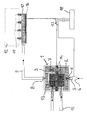
- the figure shows a fuel system according to the invention for a liquefied petroleum gas (LPG) operated internal combustion engine.
- An evaporator 1 has a first Evaporator chamber 2 and a second evaporator chamber 3. Not one illustrated pressure vessel for the propellant gas is connected via a shut-off valve 4 to a Input 5 of the evaporator 1 connected.
- a first valve 6 In the area of the entrance 5 is a first valve 6, at which the propellant gas is expanded and thereby at least partially the gaseous phase passes.
- An arranged on the second evaporator chamber 3 output 8 connects the Evaporator 1 via a line 9 with a common injection line 10.
- valves 11 are arranged, via which the propellant gas directly or indirectly via an air intake duct into the combustion chambers of a Internal combustion engine 12 is injected.
- the propellant takes heat energy from its surroundings on, the the evaporator 1 by means of a first heater 13 and a second Heating device 14 is supplied.
- the first heater 13 is connected to a Cooling circuit of the internal combustion engine 12 is coupled.
- the inside of the evaporator arranged heat exchanger of the first heater 13 extends to both Evaporator combs 2, 3 and is with the cooling liquid of the internal combustion engine 12th flows through.
- An optional thermostatic valve 15 regulates the flow of cooling fluid in Dependence on the temperature of the cooling liquid such that the first Heating device 13 is only flowed through with cooling liquid, if their Temperature exceeds a certain limit.
- the second heater 14 is heated with electrical energy, so it can be independent of the state of the Internal combustion engine 12 are operated.
- the second heater 14 is so arranged that they the separation between the first evaporator chamber 2 and the second evaporator chamber 3 forms and extends to the interior of the Heat exchanger of the first heater 13, so that heat energy from the second heater 14 directly and indirectly via the first heater 13 the propellant contained in the evaporator chambers 2, 3 is transmitted.
- a PTC heating element 14 whose temperature is automatically regulated to a preset value.
- a third Heater 16 is for heating the common rail 10 and is also equipped with a PTC heating element.
- the second, electrically operated heater ensures that the Propellant even at cold ambient temperature and with cold combustion engine in Evaporator 1 completely evaporated. This can be safely prevented that unsafe operating conditions arise from the fact that liquid propellant gas in the line 9 and enters the collective injection line 10.
- the third heater 16 prevents a recondensation of the gaseous propellant to otherwise possibly cold Walls of the collective injection line 10th
Landscapes
- Engineering & Computer Science (AREA)
- Chemical & Material Sciences (AREA)
- Combustion & Propulsion (AREA)
- Mechanical Engineering (AREA)
- General Engineering & Computer Science (AREA)
- Chemical Kinetics & Catalysis (AREA)
- General Chemical & Material Sciences (AREA)
- Oil, Petroleum & Natural Gas (AREA)
- Output Control And Ontrol Of Special Type Engine (AREA)
- Filling Or Discharging Of Gas Storage Vessels (AREA)
- Air-Conditioning For Vehicles (AREA)
Applications Claiming Priority (2)
| Application Number | Priority Date | Filing Date | Title |
|---|---|---|---|
| DE10252084A DE10252084A1 (de) | 2002-11-08 | 2002-11-08 | Kraftstoffanlage für einen LPG-Motor |
| DE10252084 | 2002-11-08 |
Publications (3)
| Publication Number | Publication Date |
|---|---|
| EP1418332A2 true EP1418332A2 (fr) | 2004-05-12 |
| EP1418332A3 EP1418332A3 (fr) | 2009-05-06 |
| EP1418332B1 EP1418332B1 (fr) | 2011-01-26 |
Family
ID=32103409
Family Applications (1)
| Application Number | Title | Priority Date | Filing Date |
|---|---|---|---|
| EP03025313A Expired - Lifetime EP1418332B1 (fr) | 2002-11-08 | 2003-11-03 | Système d'alimentation de carburant pour un moteur LPG |
Country Status (3)
| Country | Link |
|---|---|
| US (1) | US6976455B2 (fr) |
| EP (1) | EP1418332B1 (fr) |
| DE (2) | DE10252084A1 (fr) |
Cited By (6)
| Publication number | Priority date | Publication date | Assignee | Title |
|---|---|---|---|---|
| ITCB20080004A1 (it) * | 2008-11-03 | 2009-02-02 | Dec2001 Srl | Riscaldatore elettrico per il gas, gpl o metano circolante nei riduttori di pressione in auto bifuel, con motori endotermici alternativi |
| WO2011040208A1 (fr) * | 2009-09-30 | 2011-04-07 | 株式会社ケーヒン | Unité chauffante ctp et soupape de réduction de pression pour combustible gpl |
| FR2960601A1 (fr) * | 2010-06-01 | 2011-12-02 | Peugeot Citroen Automobiles Sa | Module montable sur moteur a combustion |
| ITUB20152802A1 (it) * | 2015-08-03 | 2017-02-03 | Metatronix S R L | Sistema per il condizionamento termico di un combustibile gassoso |
| ITUB20152789A1 (it) * | 2015-08-03 | 2017-02-03 | Metatronix S R L | Sistema per il condizionamento termico di un combustibile gassoso |
| WO2017157754A1 (fr) * | 2016-03-18 | 2017-09-21 | Volkswagen Aktiengesellschaft | Moteur à combustion interne et procédé permettant de faire fonctionner un moteur à combustion interne |
Families Citing this family (20)
| Publication number | Priority date | Publication date | Assignee | Title |
|---|---|---|---|---|
| US20080032245A1 (en) * | 2003-11-11 | 2008-02-07 | Vapor Fuel Technologies, Llc | Fuel utilization |
| US7028675B2 (en) * | 2003-11-11 | 2006-04-18 | Vapor Fuel Technologies, Inc. | Vapor fueled engine |
| US6907866B2 (en) * | 2003-11-11 | 2005-06-21 | Vapor Fuel Technologies, Inc. | Vapor fueled engine |
| US7631637B2 (en) * | 2006-06-01 | 2009-12-15 | Vapor Fuel Technologies, Llc | System for improving fuel utilization |
| WO2010016903A2 (fr) | 2008-08-06 | 2010-02-11 | Keith Long | Commande d’injection de propane pour moteurs à combustion interne à essence ou à combustible gazeux |
| US20110174277A1 (en) * | 2010-01-20 | 2011-07-21 | Bert Socolove | Universal hydrogen plasma carburetor |
| US20110214644A1 (en) * | 2010-03-05 | 2011-09-08 | Woodward, Inc. | Cold-Start Fuel Control System |
| BRPI1100311B1 (pt) * | 2011-02-11 | 2022-01-04 | Magneti Marelli Sistemas Automotivos Indústria E Comércio Ltda. - Divisão Controle Motor | Conjunto aquecedor de combustível com efeito fusível |
| JP5917836B2 (ja) * | 2011-06-07 | 2016-05-18 | 株式会社日本自動車部品総合研究所 | 内燃機関の燃料供給装置 |
| US20130306029A1 (en) * | 2012-05-17 | 2013-11-21 | Caterpillar Inc. | Direct Injection Gas Engine and Method |
| DE102012021410A1 (de) | 2012-10-30 | 2014-05-15 | Daimler Ag | Verbrennungskraftmaschine sowie Verfahren zum Betreiben einer Verbrennungskraftmaschine |
| KR101394854B1 (ko) * | 2012-12-28 | 2014-05-13 | 현대자동차주식회사 | 대체 연료 차량의 냉시동 개선을 위한 연료 히팅 장치 |
| US9091240B2 (en) * | 2013-01-24 | 2015-07-28 | Caterpillar Inc. | Compressed natural gas fuel mass control system |
| JP6021767B2 (ja) * | 2013-09-04 | 2016-11-09 | 日本サーモスタット株式会社 | 液化ガス加温用ヒータ装置 |
| FR3110198A1 (fr) | 2020-05-15 | 2021-11-19 | Renault S.A.S | Procede d’activation de systeme de rechauffage d’un circuit de carburant gazeux pour demarrages a froid. |
| FR3112575A1 (fr) * | 2020-07-17 | 2022-01-21 | Renault S.A.S | Rampe d'injection de carburant gaz. |
| FR3112574B1 (fr) | 2020-07-17 | 2022-09-30 | Renault Sas | Réchauffe Gaz dans Rampe d'injection avec Insert métallique |
| FR3113095B1 (fr) | 2020-07-28 | 2022-06-24 | Renault Sas | Systeme de rechauffage d’un circuit de carburant gazeux pour demarrage. |
| CN118159728A (zh) * | 2021-07-07 | 2024-06-07 | 霍尔斯动力总成解决方案有限责任公司 | 用于加热气态燃料起动回路的系统 |
| CN114837859B (zh) * | 2022-05-20 | 2023-04-07 | 重庆润通科技有限公司 | 一种燃气发电机组的发动机燃气输送管路加热控制方法 |
Family Cites Families (13)
| Publication number | Priority date | Publication date | Assignee | Title |
|---|---|---|---|---|
| JPS5831468B2 (ja) * | 1978-12-28 | 1983-07-06 | 日産自動車株式会社 | アルコ−ルエンジンの始動装置 |
| US4429534A (en) * | 1982-07-26 | 1984-02-07 | Williams International Corporation | Methanol fueled spark ignition engine |
| US4488517A (en) * | 1983-04-15 | 1984-12-18 | Conoco Inc. | Cold start method with start-up gaseous fuel generation system for methanol fueled cars |
| DE3478818D1 (en) * | 1984-11-17 | 1989-08-03 | Barbanti Bologna Bb Srl | Equipment suitable for feeding in internal combustion engine with air-l.p.g or air-methane mixture and device to regulate the strength of the mixture delivered by this equipment |
| US5443053A (en) * | 1993-07-27 | 1995-08-22 | Johnson; Jack E. | Fuel heater |
| CA2198157C (fr) * | 1996-02-21 | 2002-11-05 | Steven A. Carter | Vaporisateur de gaz basse pression et methode de fonctionnement |
| NL1003941C2 (nl) * | 1996-09-02 | 1998-03-11 | Vialle Bv | Brandstofinspuitinrichting voor een inwendige verbrandingsmotor. |
| DE19928102B4 (de) * | 1999-06-19 | 2005-06-02 | Daimlerchrysler Ag | Fahrzeug mit einem Antriebs-Verbrennungsmotor und mit einem Brennstoffzellensystem zur Stromversorgung elektrischer Verbraucher des Fahrzeugs und Verfahren zum Betrieb eines derartigen Fahrzeugs |
| US6655130B1 (en) * | 2000-10-30 | 2003-12-02 | Delphi Technologies, Inc. | System and controls for near zero cold start tailpipe emissions in internal combustion engines |
| DE10120097B4 (de) * | 2001-04-25 | 2005-07-21 | Daimlerchrysler Ag | Abgasreinigungsanlage und Verfahren zum Betreiben der Anlage |
| US6810658B2 (en) * | 2002-03-08 | 2004-11-02 | Daimlerchrysler Ag | Exhaust-gas purification installation and exhaust-gas purification method for purifying an exhaust gas from an internal combustion engine |
| US6702991B1 (en) * | 2002-11-12 | 2004-03-09 | Arvin Technologies, Inc. | Apparatus and method for reducing power consumption of a plasma fuel reformer |
| US6715452B1 (en) * | 2002-11-13 | 2004-04-06 | Arvin Technologies, Inc. | Method and apparatus for shutting down a fuel reformer |
-
2002
- 2002-11-08 DE DE10252084A patent/DE10252084A1/de not_active Withdrawn
-
2003
- 2003-11-03 EP EP03025313A patent/EP1418332B1/fr not_active Expired - Lifetime
- 2003-11-03 DE DE50313433T patent/DE50313433D1/de not_active Expired - Lifetime
- 2003-11-06 US US10/703,199 patent/US6976455B2/en not_active Expired - Fee Related
Cited By (7)
| Publication number | Priority date | Publication date | Assignee | Title |
|---|---|---|---|---|
| ITCB20080004A1 (it) * | 2008-11-03 | 2009-02-02 | Dec2001 Srl | Riscaldatore elettrico per il gas, gpl o metano circolante nei riduttori di pressione in auto bifuel, con motori endotermici alternativi |
| WO2011040208A1 (fr) * | 2009-09-30 | 2011-04-07 | 株式会社ケーヒン | Unité chauffante ctp et soupape de réduction de pression pour combustible gpl |
| FR2960601A1 (fr) * | 2010-06-01 | 2011-12-02 | Peugeot Citroen Automobiles Sa | Module montable sur moteur a combustion |
| ITUB20152802A1 (it) * | 2015-08-03 | 2017-02-03 | Metatronix S R L | Sistema per il condizionamento termico di un combustibile gassoso |
| ITUB20152789A1 (it) * | 2015-08-03 | 2017-02-03 | Metatronix S R L | Sistema per il condizionamento termico di un combustibile gassoso |
| EP3128166A1 (fr) * | 2015-08-03 | 2017-02-08 | Metatronix S.r.l. | Système de conditionnement thermique d'un combustible gazeux |
| WO2017157754A1 (fr) * | 2016-03-18 | 2017-09-21 | Volkswagen Aktiengesellschaft | Moteur à combustion interne et procédé permettant de faire fonctionner un moteur à combustion interne |
Also Published As
| Publication number | Publication date |
|---|---|
| EP1418332A3 (fr) | 2009-05-06 |
| EP1418332B1 (fr) | 2011-01-26 |
| US6976455B2 (en) | 2005-12-20 |
| US20040144370A1 (en) | 2004-07-29 |
| DE10252084A1 (de) | 2004-05-27 |
| DE50313433D1 (de) | 2011-03-10 |
Similar Documents
| Publication | Publication Date | Title |
|---|---|---|
| EP1418332B1 (fr) | Système d'alimentation de carburant pour un moteur LPG | |
| EP1192351A2 (fr) | Dispositif d'alimentation en carburant pour moteur a combustion interne | |
| DE102012007053B4 (de) | Verfahren zum Betreiben einer Brennkraftmaschine sowie Brennkraftmaschine | |
| EP0737135A1 (fr) | Appareil de chauffage de vehicules avec dispositif de surveillance de surchauffe | |
| EP3578793B1 (fr) | Système d'alimentation permettant l'alimentation en carburant gnc ou gnl | |
| DE10310345A1 (de) | Kraftstoffversorgungsvorrichtung für einen Kraftstoff mit niedrigem Siedepunkt und Verfahren zu ihrer Steuerung | |
| EP1455077B1 (fr) | Procédé d'exploitation d'un système d'alimentation de carburant pour un moteur GPL | |
| WO2017157754A1 (fr) | Moteur à combustion interne et procédé permettant de faire fonctionner un moteur à combustion interne | |
| EP2084377A1 (fr) | Procédé d'exploitation d'un moteur à combustion interne entraîné au choix au moyen d'un carburant liquide et d'un carburant gazeux et système d'alimentation en carburant | |
| EP3578794A1 (fr) | Système d'alimentation permettant l'alimentation en carburant gnc ou gnl | |
| EP1399656B1 (fr) | Procede de surveillance d'un circuit de refroidissement dans un moteur a combustion interne | |
| EP2345803A1 (fr) | Circuit de refroidissement d'un moteur à combustion interne et procédé de travail pour le fonctionnement d'un circuit de refroidissement | |
| WO1996021127A1 (fr) | Appareil de chauffage pour vehicule | |
| DE102010049713A1 (de) | Verfahren zum Betreiben eines Verdampfers für Flüssiggas und Verdampfer | |
| DE202004003914U1 (de) | Heizsystem für ein Reisemobil | |
| DE102009044905A1 (de) | Brennstoffbetriebenes Heizgerät und Fahrzeugheizsystem | |
| DE19918227B4 (de) | Otto-Direkteinspritzmotor | |
| EP1348070A1 (fr) | Systeme de refroidissement pour vehicule automobile | |
| WO2016041710A1 (fr) | Dispositif de réduction de pression pour un système d'alimentation en carburant et système d'alimentation en carburant | |
| DE102008027292A1 (de) | Brennstoffzellensystem und damit ausgestattetes Kraftfahrzeug | |
| DE102017218824A1 (de) | Verfahren und Vorrichtung zur Kraftstoffversorgung einer mit einem gasförmigen Kraftstoff betreibbaren Brennkraftmaschine | |
| EP4031761B1 (fr) | Système de démarrage à froid pour un véhicule fonctionnant au moyen de gaz comprimé et présentant une alimentation en carburant de type monocarburation | |
| EP3754166B1 (fr) | Moteur à combustion interne doté d'un système de refroidissement comprenant un refroidisseur agr | |
| EP1293654A2 (fr) | Système d'injection de carburant pour moteur a combustion interne | |
| DE10155210C2 (de) | Fahrgastraumheizung eines Kraftfahrzeugs |
Legal Events
| Date | Code | Title | Description |
|---|---|---|---|
| PUAI | Public reference made under article 153(3) epc to a published international application that has entered the european phase |
Free format text: ORIGINAL CODE: 0009012 |
|
| AK | Designated contracting states |
Kind code of ref document: A2 Designated state(s): AT BE BG CH CY CZ DE DK EE ES FI FR GB GR HU IE IT LI LU MC NL PT RO SE SI SK TR |
|
| AX | Request for extension of the european patent |
Extension state: AL LT LV MK |
|
| RIN1 | Information on inventor provided before grant (corrected) |
Inventor name: KISTNER, ANDREAS Inventor name: FIRSCHING, ANDREAS Inventor name: SEYDELL, JOACHIM Inventor name: MEY, JOERN Inventor name: WUCHERPFENNING, FRANK Inventor name: AVRAMOPOULOS, IRAKLIS |
|
| PUAL | Search report despatched |
Free format text: ORIGINAL CODE: 0009013 |
|
| AK | Designated contracting states |
Kind code of ref document: A3 Designated state(s): AT BE BG CH CY CZ DE DK EE ES FI FR GB GR HU IE IT LI LU MC NL PT RO SE SI SK TR |
|
| AX | Request for extension of the european patent |
Extension state: AL LT LV MK |
|
| 17P | Request for examination filed |
Effective date: 20091002 |
|
| 17Q | First examination report despatched |
Effective date: 20091103 |
|
| AKX | Designation fees paid |
Designated state(s): DE FR GB IT |
|
| GRAP | Despatch of communication of intention to grant a patent |
Free format text: ORIGINAL CODE: EPIDOSNIGR1 |
|
| GRAS | Grant fee paid |
Free format text: ORIGINAL CODE: EPIDOSNIGR3 |
|
| GRAA | (expected) grant |
Free format text: ORIGINAL CODE: 0009210 |
|
| AK | Designated contracting states |
Kind code of ref document: B1 Designated state(s): DE FR GB IT |
|
| REG | Reference to a national code |
Ref country code: GB Ref legal event code: FG4D Free format text: NOT ENGLISH |
|
| REF | Corresponds to: |
Ref document number: 50313433 Country of ref document: DE Date of ref document: 20110310 Kind code of ref document: P |
|
| REG | Reference to a national code |
Ref country code: DE Ref legal event code: R096 Ref document number: 50313433 Country of ref document: DE Effective date: 20110310 |
|
| PLBE | No opposition filed within time limit |
Free format text: ORIGINAL CODE: 0009261 |
|
| STAA | Information on the status of an ep patent application or granted ep patent |
Free format text: STATUS: NO OPPOSITION FILED WITHIN TIME LIMIT |
|
| 26N | No opposition filed |
Effective date: 20111027 |
|
| REG | Reference to a national code |
Ref country code: DE Ref legal event code: R097 Ref document number: 50313433 Country of ref document: DE Effective date: 20111027 |
|
| PG25 | Lapsed in a contracting state [announced via postgrant information from national office to epo] |
Ref country code: IT Free format text: LAPSE BECAUSE OF FAILURE TO SUBMIT A TRANSLATION OF THE DESCRIPTION OR TO PAY THE FEE WITHIN THE PRESCRIBED TIME-LIMIT Effective date: 20110126 |
|
| GBPC | Gb: european patent ceased through non-payment of renewal fee |
Effective date: 20111103 |
|
| REG | Reference to a national code |
Ref country code: FR Ref legal event code: ST Effective date: 20120731 |
|
| PG25 | Lapsed in a contracting state [announced via postgrant information from national office to epo] |
Ref country code: GB Free format text: LAPSE BECAUSE OF NON-PAYMENT OF DUE FEES Effective date: 20111103 |
|
| PG25 | Lapsed in a contracting state [announced via postgrant information from national office to epo] |
Ref country code: FR Free format text: LAPSE BECAUSE OF NON-PAYMENT OF DUE FEES Effective date: 20111130 |
|
| PGFP | Annual fee paid to national office [announced via postgrant information from national office to epo] |
Ref country code: DE Payment date: 20171130 Year of fee payment: 15 |
|
| REG | Reference to a national code |
Ref country code: DE Ref legal event code: R119 Ref document number: 50313433 Country of ref document: DE |
|
| PG25 | Lapsed in a contracting state [announced via postgrant information from national office to epo] |
Ref country code: DE Free format text: LAPSE BECAUSE OF NON-PAYMENT OF DUE FEES Effective date: 20190601 |