EP1418361A2 - Elektronisch geregelter Flüssigkeitsantrieb eines Ventilators - Google Patents
Elektronisch geregelter Flüssigkeitsantrieb eines Ventilators Download PDFInfo
- Publication number
- EP1418361A2 EP1418361A2 EP03256622A EP03256622A EP1418361A2 EP 1418361 A2 EP1418361 A2 EP 1418361A2 EP 03256622 A EP03256622 A EP 03256622A EP 03256622 A EP03256622 A EP 03256622A EP 1418361 A2 EP1418361 A2 EP 1418361A2
- Authority
- EP
- European Patent Office
- Prior art keywords
- fill hole
- chamber
- pressure fill
- actuator
- fluid
- Prior art date
- Legal status (The legal status is an assumption and is not a legal conclusion. Google has not performed a legal analysis and makes no representation as to the accuracy of the status listed.)
- Granted
Links
- 239000012530 fluid Substances 0.000 claims abstract description 117
- 230000008878 coupling Effects 0.000 claims abstract description 89
- 238000010168 coupling process Methods 0.000 claims abstract description 89
- 238000005859 coupling reaction Methods 0.000 claims abstract description 89
- 208000009233 Morning Sickness Diseases 0.000 claims abstract description 10
- 208000034850 Vomiting in pregnancy Diseases 0.000 claims abstract description 10
- 230000004907 flux Effects 0.000 claims description 28
- 238000000034 method Methods 0.000 claims description 14
- 230000004044 response Effects 0.000 claims description 14
- 238000002485 combustion reaction Methods 0.000 claims description 7
- 238000004891 communication Methods 0.000 claims description 5
- 238000005086 pumping Methods 0.000 claims description 4
- 230000004913 activation Effects 0.000 claims description 3
- 239000002991 molded plastic Substances 0.000 claims description 3
- 230000003213 activating effect Effects 0.000 claims 2
- 238000000465 moulding Methods 0.000 claims 1
- 238000013461 design Methods 0.000 abstract description 3
- 238000001816 cooling Methods 0.000 description 9
- 239000002826 coolant Substances 0.000 description 3
- 239000000463 material Substances 0.000 description 3
- 230000008901 benefit Effects 0.000 description 2
- 230000008859 change Effects 0.000 description 2
- 238000003754 machining Methods 0.000 description 2
- 230000007257 malfunction Effects 0.000 description 2
- 239000003570 air Substances 0.000 description 1
- 239000012080 ambient air Substances 0.000 description 1
- 238000013459 approach Methods 0.000 description 1
- 230000004323 axial length Effects 0.000 description 1
- 238000010276 construction Methods 0.000 description 1
- 230000003247 decreasing effect Effects 0.000 description 1
- 230000001419 dependent effect Effects 0.000 description 1
- 230000005284 excitation Effects 0.000 description 1
- 239000000446 fuel Substances 0.000 description 1
- 239000007788 liquid Substances 0.000 description 1
- 238000004519 manufacturing process Methods 0.000 description 1
- 238000012986 modification Methods 0.000 description 1
- 230000004048 modification Effects 0.000 description 1
- 230000001953 sensory effect Effects 0.000 description 1
- 229910001220 stainless steel Inorganic materials 0.000 description 1
- 239000010935 stainless steel Substances 0.000 description 1
- 229920001187 thermosetting polymer Polymers 0.000 description 1
- XLYOFNOQVPJJNP-UHFFFAOYSA-N water Substances O XLYOFNOQVPJJNP-UHFFFAOYSA-N 0.000 description 1
Images



Classifications
-
- F—MECHANICAL ENGINEERING; LIGHTING; HEATING; WEAPONS; BLASTING
- F16—ENGINEERING ELEMENTS AND UNITS; GENERAL MEASURES FOR PRODUCING AND MAINTAINING EFFECTIVE FUNCTIONING OF MACHINES OR INSTALLATIONS; THERMAL INSULATION IN GENERAL
- F16D—COUPLINGS FOR TRANSMITTING ROTATION; CLUTCHES; BRAKES
- F16D35/00—Fluid clutches in which the clutching is predominantly obtained by fluid adhesion
- F16D35/02—Fluid clutches in which the clutching is predominantly obtained by fluid adhesion with rotary working chambers and rotary reservoirs, e.g. in one coupling part
- F16D35/021—Fluid clutches in which the clutching is predominantly obtained by fluid adhesion with rotary working chambers and rotary reservoirs, e.g. in one coupling part actuated by valves
- F16D35/024—Fluid clutches in which the clutching is predominantly obtained by fluid adhesion with rotary working chambers and rotary reservoirs, e.g. in one coupling part actuated by valves the valve being actuated electrically, e.g. by an electromagnet
Definitions
- the invention relates generally to fan drive systems and more specifically to an electronically controlled viscous fan drive.
- the present invention relates to fluid coupling devices of the type including both fluid operating chamber and a fluid reservoir chamber, and valving which controls the quantity of fluid in the operating chamber.
- the present invention may be used advantageously in fluid coupling devices having various configurations and applications, it is especially advantageous in a coupling device of the type used to drive a radiator cooling fan of an internal combustion engine, and will be described in connection therewith.
- Fluid coupling devices of the viscous shear type have been popular for many years for driving engine cooling fans, primarily because their use results in substantial saving of engine horsepower.
- the typical fluid coupling device operates in the engaged, relatively higher speed condition only when cooling is needed, and operates in a disengaged, relatively lower speed condition when little or no cooling is required.
- a typical viscous fan drive includes one or more fill openings, through which viscous fluid flows from the reservoir into the operating chamber, and one or more discharge openings through which fluid is pumped from the operating chamber back into the reservoir. After the fan drive has been operating for a period of time, and the engine is turned off, the fan drive ceases rotation.
- the orientation of the fill and discharge openings is completely unpredictable, i.e., the fill opening could be in the three o'clock position and the discharge opening could be in the nine o'clock position, in which case there would probably be relatively little “drain back” or “bleed back”, i.e., a flow of fluid from the reservoir back into the operating chamber.
- the fan drive could stop with the discharge opening in the six o'clock position and the fill opening in the twelve o'clock position, in which case the discharge opening would be beneath the level of fluid in the reservoir.
- it has been conventional for a certain amount of fluid to bleed back from the reservoir through the discharge opening, into the operating chamber.
- the fan drive would initially operate in the engaged condition for a period of time until most of the fluid in the operating chamber is pumped back into the reservoir.
- such engaged operation results in an undesirable noise of the fan being driven when it is not required. It is this phenomenon, most common and perhaps most objectionable in the morning, which has been referred to as "morning sickness".
- valve arm does not seal tightly over the fill opening, bleed back will occur.
- the valve arm will open (or remain open) and allow fluid to flow from the reservoir into the operating chamber.
- an electronically controlled fan drive this is of the "failsafe ON" type will have its valve opened when the electrical power is turned off.
- the present invention addresses some of the issues described above by providing an electronically controlled viscous fan drive system having a one-piece accumulator and reservoir located on the top side of the clutch.
- the accumulator also has a low pressure and high pressure fill hole for allowing movement of viscous fluid from the reservoir to a antibleedback chamber and into the operating and working chamber of the coupling during normal operation.
- a radially balance valve disk having a step up feature coupled to a spring and an actuator electronically controls movement of viscous fluid from the reservoir to the antibleedback chamber through the fill holes by energizing or deenergizing the spring based on engine operating conditions.
- the step up feature of the valve disk allows a more controlled flow of viscous fluid by allowing the opening of the low pressure and high pressure fill holes separately as a function of valve disk positioning.
- the actuator may be electronically activated to pull the spring downward, thereby closing the high pressure and/or low pressure fill holes to prevent viscous fluid movement to the operating chamber, during engine on conditions when engine operating conditions require no clutch engagement (i.e. no cooling required from the viscous fan drive).
- the present invention is failsafe to prevent damage to engine components if there is malfunctioning of the actuator or a loss of electrical power to the actuator.
- the antibleedback chamber in the accumulator also prevents morning sickness in the fluid coupling device regardless of the positioning of the accumulator when the engine is turned off.
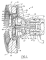
- Figure 1 is a perspective view of a fluid coupling device according to one preferred embodiment of the present invention in the disengaged position
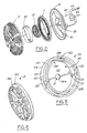
- Figure 2 is an exploded view of Figure 1;
- Figure 3 is a side view of the accumulator of Figure 2;
- Figure 4 is a side view of the circular valve disk of Figure 2;
- Figure 5 is a perspective view of a fluid coupling device of Figure 1 in a partially engaged position
- Figure 6 is a perspective view of a fluid coupling device of Figure 1 in a fully engaged position
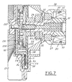
- Figure 7 is a perspective view of a fluid coupling device according to another preferred embodiment of the present invention in the disengaged position.
- Figure 8 is a side view of the two-piece circular valve disk of Figure 7.
- Figure 1 illustrates one preferred form of a fluid coupling device 10 ("viscous fan drive") of a type utilizing the present invention.
- the fluid coupling device of Figure 1 includes an input coupling member generally designated 11, and an output coupling assembly, generally designated 13.
- the assembly 13 includes a die cast housing member (body) 15, and a die cast cover member (enclosure) 17, the members 15 and 17 being secured together by a rollover of the outer periphery of the cover member 17, as is well known in the art.
- the present invention is not limited to use with a cast cover member, but may also be used in a viscous fan drive of the type including a stamped cover member.
- the fluid coupling device 10 is adapted to be driven by a liquid cooled engine, and in turn, drives a radiator cooling fan, neither of which are shown herein.
- the fan may be attached to the housing member 15 by any suitable means, such as is generally well known in the art, and as is illustrated in the above-incorporated patents. It should be understood, however, that the use of the present invention is not limited to any particular configuration of fluid coupling device, or fan mounting arrangement, or any particular application for the fan drive, except as is specifically noted hereinafter.
- the present invention could be used with a fan drive of the type adapted to have the radiator cooling fan attached to the cover member, rather than to the body member.
- the coupling device 10 includes an input coupling assembly 38 on which the input coupling member 11, or clutch, is mounted.
- the input coupling assembly 38 is rotatably driven, such as by means of an hexagonal, internally threaded portion 21, which would typically be threaded onto an externally threaded shaft extending from the engine water pump.
- the input coupling assembly 38 also has stainless steel, trapezoidal shaped piece 27 and a nose end portion 22, in which the piece 27 is preferably friction welded to and between the threaded portion 21 and a nose end portion 22. In other embodiments, the piece 27 could be brazed or simply welded to and between the threaded portion 21 and the nose end portion 27.
- the assembly 38 functions as a support for the inner race of a bearing set 25, which is seated on the inside diameter of the housing member 15.
- the forward end (left end in FIG. 1) of the actuator shaft 19 has an interference fit between the nose portion 22 and an opening defined by a hub portion 29 of the input coupling member 11.
- rotation of the assembly 38 causes rotation of the actuator shaft 19 and input coupling member 11.
- An actuator piston 23 is also coupled to a portion of the actuator shaft 19, therein forming an actuator shaft assembly 41 (shown best on FIG. 2).
- the housing member 15 and the cover member 17 cooperate to define a fluid chamber, which is separated by means of a substantially circular valve disk 31 and accumulator 59, into a fluid operating chamber 33 and a fluid reservoir chamber 35.
- the valve plate 31 is operatively coupled with the innermost end 19b (left end of FIG 1) of the actuator shaft 19.
- the fluid reservoir chamber 35 is defined by the cover member 17 and accumulator 59
- the fluid operating chamber 33 is defined by the accumulator 59 and housing member 15. It may also be seen that the valve disk 31 is disposed within the accumulator 59 and the input coupling member 11.
- valve disk 31 The relative positioning of the valve disk 31 with respect to the accumulator 59, as controlled by a return spring 50 coupled to the valve disk 31 that is biased or unbiased by an actuator piston 23 magnetically driven by the actuator 20 is a key aspect of the present invention and is used to control the amount of a viscous fluid (not shown) contained in the operating chamber 33 and reservoir chamber 35, respectively and will be discussed in detail further below.
- the cover member 17 Disposed adjacent the radially outer periphery of the operating chamber 33, the cover member 17 includes a pumping element 47, also referred to as a "wiper" element, operable to engage the relatively rotating fluid in the operating chamber 33, and generate a localized region of relatively higher fluid pressure.
- the pumping element 47 continually pumps a small quantity of fluid from the operating chamber 33 back into the reservoir chamber 35 through a radial passage 26 defined by the cover member 17, in a manner well known in the art.
- the input coupling member 11 includes a forward surface which defines a plurality of annular lands 53.
- the adjacent surface of the cover member 17 forms a plurality of annular lands 55.
- the annular lands 53 and 55 are interdigitated to define a serpentine-shaped viscous shear space 54 therebetween. It is believed that in view of the above-incorporated U.S. Patents, those skilled in the art can fully understand the construction and operation of the fluid coupling device illustrated in FIG. 1, as well as the various flow paths for the viscous fluid.
- the anti-drain back structure of the present invention could also be used in fan drives in which the lands and grooves are formed between the input coupling member and the housing (body) member.
- the accumulator 59 is preferably made of a molded plastic material and contains an anti-bleed back chamber 102 defined by an inner circular ring 104 and an outer circular ring 106 and by the input coupling member 11.
- the inner circular ring 104 has a inner top region 105.
- the inner circular ring 104 also has a low pressure fill hole 112 and a high pressure fill hole 114.
- Contained within an inner portion 108 of the inner circular ring 104 is a plate region 110.
- the plate region 110, inner portion 108, and input coupling member 11 define the reservoir chamber 35.
- the plate region 110 also has a central region 111 that contains an opening 112a for return of viscous fluid through the radial passage 26.
- the outer circular ring 106 has a pair of open regions 120 that are in open communication with the operating chamber 33 and disposed inapposite of one another around the outer circumference 122 of the outer circular ring 106.
- the outer circular ring 106 has a top region 107. When coupled, the inner top region 105 and outer top region 107 substantially seal to the input coupling member 11, therein further defining the fluid reservoir chamber 35 and anti-bleedback chamber 102
- the valve disk 31 has an outer step region 152 and an inner step region 154.
- the valve disk 31 is also preferably made of a molded plastic material.
- the step regions 152, 154 are used to regulate the amount of fluid pressure exiting through the fill holes 112,114 of the accumulator 59 during operation of the coupling member 10 to control the rotation of the cover member 17.
- an external controller portion (not shown) of the actuator 20 activates the electrical coil 77, therein creating a magnetic flux through the input coupling assembly 38 within the viscous fan drive 10.
- the actuator 20 is electrically coupled to an outside power source (not shown) and external sensory control (not shown) through electrical coupling 45 having electrical leads 49 in a method well known in the art.
- valve disk 31 As the actuator shaft 19 (and actuator coupling assembly 38) and valve disk 31 are coupled to the actuator piston 23, they are pulled rightward as well, thereby causing the inner step region 154 to cover the low pressure fill hole 112 and the outer step region 152 to cover the high pressure fill hole 114, thereby preventing the movement of viscous fluid from the reservoir chamber 35 to the anti-bleedback chamber.
- the amount of electrical power supplied in terms of pulse width modulation from the external controller and power source, and hence the amount of magnetic flux created to drive the actuator piston 23 rightward in response, is determined by the external controller.
- the controller receives a set of electrical inputs from various engine sensors (not shown) that monitor various engine operating conditions relating to engine temperature.
- these sensors could be an engine mounted coolant sensor or a pressure sensor mounted to the air conditioner.
- the controller determines that one or more of these sensors is sensing an engine operating conditions outside the desired range, the external controller and power source will send electrical power to the coil 77 as a function of this electrical signal.
- a signal may be sent from the controller to the actuator 20 activate the coil 77 to a desired pulse width, therein driving the actuator piston 23 and spring 50 to open the low pressure fill hole 112 or to open both the low pressure and high pressure fill holes 112, 114 in order to provide increased viscous fluid flow to the working chamber 54.
- a signal may be sent from the external controller to the coil 77 to provide maximum pulse width modulation to allow the inner and outer step regions 152,154 to completely cover the low and high pressure fill holes 112, 114.
- no viscous fluid will enter the operating chamber 35 or working chamber 54 through the fill holes 112, 114, and the amount of slippage in the lands 53, 55 between the input coupling device 11 and cover member 17 to drive the cover member 17 will decrease to disengaged speed.
- the low pressure fill hole 112 is located at 6 o'clock and the high pressure fill hole 114 (or vice versa) is located at 12 o'clock, viscous fluid will drain through the low pressure fill hole and into the antibleedback chamber 102.
- the open region 120 associated with the antibleedback chamber 102 is at all times above the level of the viscous fluid within the chamber 102, thereby preventing the flow of viscous fluid into the operating chamber 33.
- the same scenario would be true for any orientation in which one fill hole 112, 114 is located below the level of the viscous fluid.
- the low pressure fill hole 112 is located at 3 and the high pressure fill hole 114 is located at 9 o'clock, then neither fill hole 112, 114 is covered with viscous fluid. Thus, all of the viscous fluid remains in the reservoir chamber 35.
- the viscous fan drive will be left in an engaged position, therein allowing the cover member 17 to rotate at maximum speed. This prevents engine damage associated with high temperatures.
- the actual amount of pulse width modulation necessary to energize the coil 77 is dependent upon many factors.
- the size and shape of the spring 50 itself is a major factor is the amount of pulse width modulation necessary to move the actuator piston 23.
- a stiffer or larger spring 50 may require a larger pulse width to achieve a similar biasing of the spring 50 as compared with a more flexible or smaller spring.
- the size of the fill holes 112, 114 may affect the amount of biasing necessary. For example, an accumulator 59 with larger fill holes 112,114 may only require the valve disk 31 to slightly uncover one or both of the fill holes 112, 114 in order to provide adequate viscous fluid flow to the working chamber.
- FIGS 7 and 8 illustrate another preferred embodiment of the present invention, in which a two-piece valve disk 231 replaces the one-piece valve disk 31.
- the two-piece valve disk 231 comprises an inner disk 233 and an outer disk 235.
- the inner disk 233 has a structure similar to the inner step region 154 of the valve disk 31 of Figures 1-6 and functions to cover or uncover the low pressure fill hole 112.
- the inner disk 233 is coupled to the spring member 50 and moves from a disengaged to partially engaged to engaged position in substantially the same manner and the inner step region 154 of the valve disk in Figures 1-6.
- the outer disk 235 has a structure similar to the outer step region 152 and functions to cover or uncover the high pressure fill hole 114, which is now located closer to the input coupling member 11 as shown in Figure 7.
- the outer disk 235 also contains a plurality of spring fingers 237 located on its outer periphery. Spring fingers 237 work against the low pressure fill hole step 113 (shown best in FIG. 8) holding the outer disk 235 in position covering the high pressure fill hole 114.
- the outer disk 235 only moves when the actuator 23 forces the inner disk 233 near the top of its travel towards the outer disk 235.
- the inner disk 233 then engages the spring fingers 237 of outer disk 235, thereby pushing the outer disk towards the actuator piston 23 to uncover the high pressure fill hole 114.
- the spring fingers 237 require additional force to move against it in order to move the outer disk 235 (i.e. there is play between the inner disk 233 the outer disk 237 before the inner disk 233 engages the outer disk 237 moves to uncover the high pressure fill hole 114.
- This is advantageous because small changes in ambient temperatures, and hence small changes in the amount of actuation (movement of the actuator piston 23) in the form of electrical excitation of the coils 77 will not significantly change the relative positioning of the outer disk 237 as compared to the change in relative positioning of outer step region 152 of Figures 1-6.
- the two-piece valve disk 231 may in fact be easier to control in covering and uncovering the fill holes 112,114 than the one-piece disk 31.
- the present invention offers many improvements over previous fluid coupling devices 10.
- the accumulator 59 is easily manufactured from a thermosetting molded material and offers a substantial cost savings.
- no orientation of the valve disk 31, 231 is required, as the design will prevent morning sickness regardless of the valve disk 31, 231 positioning in engine off conditions..
- pressure changes due to speed variations of the input coupling devices 11 are balanced or eliminated.
- the present invention offers a shorter axial length than currently available reservoirs, thus allowing the fluid coupling device 10 to use less space in the engine compartment.
- the present invention is instantaneously controllable by simply energizing or deenergizing the coil 77 to cover or uncover the high pressure and low pressure fill holes 112,114, which allows for improved fuel economy.
- the arrangement of the components is set in a failsafe engaged position, thereby protecting engine components by maintaining viscous fluid in the working chamber 54 during electrical outages or actuator 20 malfunctions.
Landscapes
- Engineering & Computer Science (AREA)
- General Engineering & Computer Science (AREA)
- Physics & Mathematics (AREA)
- Electromagnetism (AREA)
- Mechanical Engineering (AREA)
- Valve Device For Special Equipments (AREA)
- Hydraulic Clutches, Magnetic Clutches, Fluid Clutches, And Fluid Joints (AREA)
- Jet Pumps And Other Pumps (AREA)
Applications Claiming Priority (2)
| Application Number | Priority Date | Filing Date | Title |
|---|---|---|---|
| US287325 | 2002-11-04 | ||
| US10/287,325 US6752251B2 (en) | 2002-11-04 | 2002-11-04 | Electronically controlled viscous fan drive |
Publications (3)
| Publication Number | Publication Date |
|---|---|
| EP1418361A2 true EP1418361A2 (de) | 2004-05-12 |
| EP1418361A3 EP1418361A3 (de) | 2004-05-19 |
| EP1418361B1 EP1418361B1 (de) | 2006-03-08 |
Family
ID=32107617
Family Applications (1)
| Application Number | Title | Priority Date | Filing Date |
|---|---|---|---|
| EP03256622A Expired - Lifetime EP1418361B1 (de) | 2002-11-04 | 2003-10-21 | Elektronisch geregelter Flüssigkeitsantrieb eines Ventilators |
Country Status (4)
| Country | Link |
|---|---|
| US (1) | US6752251B2 (de) |
| EP (1) | EP1418361B1 (de) |
| JP (1) | JP4410530B2 (de) |
| DE (1) | DE60303892T2 (de) |
Cited By (5)
| Publication number | Priority date | Publication date | Assignee | Title |
|---|---|---|---|---|
| EP1630443A3 (de) * | 2004-08-30 | 2007-02-14 | BorgWarner Inc. | Elektronisch geregelte Flüssigkeitskupplungseinrichtung |
| EP1985882A1 (de) | 2007-04-23 | 2008-10-29 | Behr GmbH & Co. KG | Flüssigkeitsreibungskupplung für den Antrieb eines Lüfters in einem Kraftfahrzeug |
| EP1913273A4 (de) * | 2005-07-29 | 2013-10-23 | Horton Inc | Viskosekupplung |
| WO2017096202A1 (en) | 2015-12-03 | 2017-06-08 | Horton, Inc. | Viscous clutch fluid capture system |
| US10578171B2 (en) | 2015-10-05 | 2020-03-03 | Horton, Inc. | Morning sickness valve system for viscous clutch |
Families Citing this family (29)
| Publication number | Priority date | Publication date | Assignee | Title |
|---|---|---|---|---|
| DE102004009073A1 (de) * | 2004-02-23 | 2005-09-15 | Behr Gmbh & Co. Kg | Regelbarer Antrieb für ein Kraftfahrzeug |
| US7980373B2 (en) * | 2004-08-30 | 2011-07-19 | Borgwarner Inc. | Electronically controlled fluid coupling device with fluid scavenge control |
| JP4813868B2 (ja) * | 2004-11-09 | 2011-11-09 | 臼井国際産業株式会社 | 外部制御式ファン・カップリング装置 |
| US7650974B2 (en) * | 2005-05-02 | 2010-01-26 | Borgwarner Inc. | OD wiper |
| US7293636B2 (en) * | 2005-05-02 | 2007-11-13 | Borgwarner Inc. | Electronically controlled viscous fan drive having cast channels |
| US20060243817A1 (en) * | 2005-05-02 | 2006-11-02 | Borgwarner Inc. | Viscous fan drive with a fluid control valve |
| US7621386B2 (en) * | 2006-03-02 | 2009-11-24 | Borgwarner Inc. | Viscous fan drive having modified land design and armature venting |
| WO2008101136A1 (en) * | 2007-02-15 | 2008-08-21 | Borgwarner Inc. | Viscous coolant heater with variable coolant pump drive |
| US7891178B2 (en) * | 2008-01-17 | 2011-02-22 | Nikco, Llc | Centrifugally balanced fluid reservoir and method of use thereof |
| CN102066711B (zh) | 2008-05-13 | 2013-10-23 | 博格华纳公司 | 具有套管的电子控制的粘性风扇驱动器 |
| US9435386B2 (en) * | 2009-09-24 | 2016-09-06 | Mahle International Gmbh | Fluid friction clutch |
| CN104832266B (zh) * | 2009-10-17 | 2017-12-01 | 博格华纳公司 | 带有电动机的混合动力型风扇驱动器 |
| BR112012011837A2 (pt) | 2009-11-17 | 2018-09-11 | Horton Inc | embreagem viscosa integrada |
| KR101799073B1 (ko) | 2010-08-19 | 2017-11-17 | 호르톤 인코포레이티드 | 비스커스 클러치 밸브 조립체 |
| EP2626584B1 (de) | 2012-02-08 | 2014-03-26 | BorgWarner Inc. | Flüssigkeitsreibungskupplung |
| US9624988B2 (en) | 2012-09-22 | 2017-04-18 | Horton, Inc. | Viscous clutch with return bore through rotor |
| AU2014240621B2 (en) | 2013-03-14 | 2017-06-29 | Horton, Inc. | Viscous clutch and associated reservoir configuration |
| JP6200060B2 (ja) | 2013-03-14 | 2017-09-20 | ホートン, インコーポレイテッド | 最低出力速度を備えた粘性クラッチ |
| KR101305399B1 (ko) * | 2013-06-26 | 2013-09-06 | (주)쿨링시스템 | 유체 팬 클러치 |
| US9587683B2 (en) | 2014-10-19 | 2017-03-07 | Borgwarner Inc. | Viscous clutch drive with electromagnetic activation and wiper on clutch disk |
| US9664238B2 (en) | 2014-10-19 | 2017-05-30 | Borgwarner Inc. | Bimetal activated viscous clutch with wiper on clutch disk |
| US20160123409A1 (en) * | 2014-11-01 | 2016-05-05 | Borgwarner Inc. | Viscous clutch with high-speed reservoir and bimetal coil member |
| US20160123410A1 (en) * | 2014-11-01 | 2016-05-05 | Borgwarner Inc. | Viscous clutch with high-speed reservoir, valve in housing, and bimetal member |
| US9470278B1 (en) | 2015-11-10 | 2016-10-18 | Borgwarner Inc. | Apparatus employing shear forces to transmit energy having flow altering structures configured to increase heat rejection from a working fluid and related method |
| CN107687487B (zh) * | 2017-08-15 | 2019-10-22 | 雪龙集团股份有限公司 | 一种硅油风扇离合器 |
| US10655688B2 (en) | 2018-02-16 | 2020-05-19 | Standard Motor Products, Inc. | Fan-coupling device with unitary magnetic pole construction |
| EP3788273B1 (de) | 2018-05-02 | 2024-07-03 | Horton, Inc. | Energiegewinnungskupplungssteuerungsanordnung, ventilanordnung und elektrisch betätigte kupplung |
| CN108798862A (zh) * | 2018-08-22 | 2018-11-13 | 温州车舟汽车部件有限公司 | 一种电控硅油离合器 |
| EP3918220B1 (de) | 2019-01-31 | 2023-08-30 | Horton, Inc. | Pumpe und wischeranlage, zugehörige viskosekupplung und zugehöriges verfahren |
Citations (3)
| Publication number | Priority date | Publication date | Assignee | Title |
|---|---|---|---|---|
| US4312433A (en) | 1978-10-02 | 1982-01-26 | Eaton Corporation | Viscous fluid clutch and standpipe arrangement therefor |
| US5101950A (en) | 1990-12-26 | 1992-04-07 | Eaton Corporation | Fluid coupling device with improved dump time |
| US6085881A (en) | 1999-02-22 | 2000-07-11 | Borgwarner Inc. | Fluid coupling device and anti-drain back structure therefor |
Family Cites Families (18)
| Publication number | Priority date | Publication date | Assignee | Title |
|---|---|---|---|---|
| US4190140A (en) | 1978-05-26 | 1980-02-26 | Eaton Corporation | Fluid coupling device, bimetal clip and method of assembly therefor |
| US4362226A (en) * | 1978-10-04 | 1982-12-07 | Eaton Corporation | Viscous fluid clutch and reservoir by-pass valve therefor |
| US4310085A (en) * | 1979-09-06 | 1982-01-12 | General Motors Corporation | Electro-viscous fan clutch |
| US4828088A (en) * | 1987-05-18 | 1989-05-09 | Eaton Corporation | Closed loop pulse modulated viscous fan control |
| US5113987A (en) * | 1991-02-07 | 1992-05-19 | General Motors Corporation | Fluid return channels for a cover of a viscous fluid clutch |
| DE4390685T1 (de) * | 1992-02-27 | 1994-04-28 | Usui Kokusai Sangyo Kk | Temperaturabhängige Flüssigkeitskupplung für einen Ventilator |
| DE4344085C2 (de) | 1993-12-23 | 1999-07-15 | Behr Gmbh & Co | Elektromagnetisch gesteuerte Flüssigkeitsreibungskupplung |
| US5558192A (en) | 1995-03-27 | 1996-09-24 | Eaton Corporation | Fluid coupling and external control therefor |
| JP3786374B2 (ja) | 1995-11-10 | 2006-06-14 | 臼井国際産業株式会社 | 液体クラッチ |
| US5893442A (en) | 1997-04-09 | 1999-04-13 | Eaton Corporation | Heavy duty viscous fan drive and bracket mounting assembly therefor |
| US6056098A (en) * | 1998-02-04 | 2000-05-02 | Borg-Warner Automotive, Inc. | Viscous fluid coupling and improved valve assembly therefor |
| US6021747A (en) * | 1998-02-16 | 2000-02-08 | Eaton Corporation | Water cooled viscous fan drive |
| DE19915871A1 (de) | 1998-04-09 | 1999-10-21 | Unisia Jecs Corp | Viskosefluidkupplung |
| US6026943A (en) | 1999-04-16 | 2000-02-22 | Eaton Corporation | Segmented reservoir for viscous clutches |
| DE19925132B4 (de) * | 1999-06-02 | 2016-08-04 | Mahle International Gmbh | Flüssigkeitsreibungskupplung |
| DE19940099B4 (de) | 1999-08-24 | 2016-09-01 | Horton Europe Gmbh & Co. Kg | Flüssigkeitsreibungskupplung |
| GB2358697B (en) * | 2000-01-28 | 2004-03-17 | Agco Gmbh & Co | Liquid friction clutch |
| DE10012648A1 (de) * | 2000-03-15 | 2001-10-04 | Mannesmann Sachs Ag | Fluidkupplung |
-
2002
- 2002-11-04 US US10/287,325 patent/US6752251B2/en not_active Expired - Lifetime
-
2003
- 2003-10-21 DE DE60303892T patent/DE60303892T2/de not_active Expired - Lifetime
- 2003-10-21 EP EP03256622A patent/EP1418361B1/de not_active Expired - Lifetime
- 2003-10-22 JP JP2003361776A patent/JP4410530B2/ja not_active Expired - Fee Related
Patent Citations (3)
| Publication number | Priority date | Publication date | Assignee | Title |
|---|---|---|---|---|
| US4312433A (en) | 1978-10-02 | 1982-01-26 | Eaton Corporation | Viscous fluid clutch and standpipe arrangement therefor |
| US5101950A (en) | 1990-12-26 | 1992-04-07 | Eaton Corporation | Fluid coupling device with improved dump time |
| US6085881A (en) | 1999-02-22 | 2000-07-11 | Borgwarner Inc. | Fluid coupling device and anti-drain back structure therefor |
Cited By (13)
| Publication number | Priority date | Publication date | Assignee | Title |
|---|---|---|---|---|
| US7278524B2 (en) | 2004-08-30 | 2007-10-09 | Borgwarner Inc. | Electronically controlled fluid coupling device |
| EP1630443A3 (de) * | 2004-08-30 | 2007-02-14 | BorgWarner Inc. | Elektronisch geregelte Flüssigkeitskupplungseinrichtung |
| EP1913273A4 (de) * | 2005-07-29 | 2013-10-23 | Horton Inc | Viskosekupplung |
| DE102007019088B4 (de) | 2007-04-23 | 2018-07-26 | Mahle International Gmbh | Flüssigkeitsreibungskupplung für den Antrieb eines Lüfters in einem Kraftfahrzeug |
| EP1985882A1 (de) | 2007-04-23 | 2008-10-29 | Behr GmbH & Co. KG | Flüssigkeitsreibungskupplung für den Antrieb eines Lüfters in einem Kraftfahrzeug |
| DE102007019088A1 (de) | 2007-04-23 | 2008-10-30 | Behr Gmbh & Co. Kg | Flüssigkeitsreibungskupplung für den Antrieb eines Lüfters in einem Kraftfahrzeug |
| US7886886B2 (en) | 2007-04-23 | 2011-02-15 | Behr Gmbh & Co. Kg | Viscous friction clutch for driving a cooling fan in a motor vehicle |
| US10578171B2 (en) | 2015-10-05 | 2020-03-03 | Horton, Inc. | Morning sickness valve system for viscous clutch |
| US10578170B2 (en) | 2015-10-05 | 2020-03-03 | Horton, Inc. | Live center viscous clutch |
| EP3384174A4 (de) * | 2015-12-03 | 2019-08-28 | Horton, Inc. | System zur erfassung einer viskosekupplungsflüssigkeit |
| WO2017096202A1 (en) | 2015-12-03 | 2017-06-08 | Horton, Inc. | Viscous clutch fluid capture system |
| US10578172B2 (en) | 2015-12-03 | 2020-03-03 | Horton, Inc. | Viscous clutch fluid capture system |
| US10612605B2 (en) | 2015-12-03 | 2020-04-07 | Horton, Inc. | Viscous clutch fluid capture system |
Also Published As
| Publication number | Publication date |
|---|---|
| DE60303892T2 (de) | 2006-11-23 |
| JP2004156780A (ja) | 2004-06-03 |
| US6752251B2 (en) | 2004-06-22 |
| US20040084273A1 (en) | 2004-05-06 |
| EP1418361A3 (de) | 2004-05-19 |
| JP4410530B2 (ja) | 2010-02-03 |
| EP1418361B1 (de) | 2006-03-08 |
| DE60303892D1 (de) | 2006-05-04 |
Similar Documents
| Publication | Publication Date | Title |
|---|---|---|
| US6752251B2 (en) | Electronically controlled viscous fan drive | |
| EP0010378B1 (de) | Flüssigkeitskupplung mit Vorratskammer und By-pass Ventil | |
| EP0015643B1 (de) | Flüssigkeitskupplung mit verbesserter Reaktionszeit | |
| US8602190B2 (en) | Electronically controlled viscous fan drive with bushing | |
| US8701852B2 (en) | Viscous fan drive systems having fill and scavenge control | |
| EP2280184B1 (de) | Segmentiertes Reservoir für Viskose-Kupplungen | |
| US7963380B2 (en) | OD wiper | |
| EP0935080B1 (de) | Flüssigkeitsreibungskupplung mit verbesserter Ventilanordnung | |
| EP1630443B1 (de) | Elektronisch geregelte Flüssigkeitskupplungseinrichtung | |
| JP2775431B2 (ja) | 感温作動型流体式フアン・カツプリング装置 | |
| US7293636B2 (en) | Electronically controlled viscous fan drive having cast channels | |
| US7621386B2 (en) | Viscous fan drive having modified land design and armature venting | |
| EP1621787B1 (de) | Flüssigkeitsreibungsantrieb eines Ventilators mit einem Dichtelement zwischen einem Ausgangsgehäusedeckel und einem Körper auf der Eingangswelle | |
| EP1031750B1 (de) | Kupplungsvorrichtung für Flüssigkeiten mit Antirückflusseinrichtung | |
| US20140209180A1 (en) | Viscous fan drive systems having fill and scavenge control | |
| US20060243817A1 (en) | Viscous fan drive with a fluid control valve | |
| JPH0733854B2 (ja) | 粘性流体クラッチのための予荷重された制御アーム | |
| JPS5918180Y2 (ja) | 自動車用ク−ラのコンプレッサ駆動用カップリング | |
| JPH0451222Y2 (de) | ||
| JP2541886Y2 (ja) | 感温作動型流体式ファン・カップリング装置 |
Legal Events
| Date | Code | Title | Description |
|---|---|---|---|
| PUAI | Public reference made under article 153(3) epc to a published international application that has entered the european phase |
Free format text: ORIGINAL CODE: 0009012 |
|
| PUAL | Search report despatched |
Free format text: ORIGINAL CODE: 0009013 |
|
| AK | Designated contracting states |
Kind code of ref document: A2 Designated state(s): AT BE BG CH CY CZ DE DK EE ES FI FR GB GR HU IE IT LI LU MC NL PT RO SE SI SK TR |
|
| AX | Request for extension of the european patent |
Extension state: AL LT LV MK |
|
| AK | Designated contracting states |
Kind code of ref document: A3 Designated state(s): AT BE BG CH CY CZ DE DK EE ES FI FR GB GR HU IE IT LI LU MC NL PT RO SE SI SK TR |
|
| AX | Request for extension of the european patent |
Extension state: AL LT LV MK |
|
| 17P | Request for examination filed |
Effective date: 20040616 |
|
| AKX | Designation fees paid |
Designated state(s): DE GB SE |
|
| 17Q | First examination report despatched |
Effective date: 20050113 |
|
| RAP1 | Party data changed (applicant data changed or rights of an application transferred) |
Owner name: BORGWARNER INC. |
|
| GRAP | Despatch of communication of intention to grant a patent |
Free format text: ORIGINAL CODE: EPIDOSNIGR1 |
|
| GRAS | Grant fee paid |
Free format text: ORIGINAL CODE: EPIDOSNIGR3 |
|
| GRAA | (expected) grant |
Free format text: ORIGINAL CODE: 0009210 |
|
| AK | Designated contracting states |
Kind code of ref document: B1 Designated state(s): DE GB SE |
|
| REG | Reference to a national code |
Ref country code: GB Ref legal event code: FG4D |
|
| REF | Corresponds to: |
Ref document number: 60303892 Country of ref document: DE Date of ref document: 20060504 Kind code of ref document: P |
|
| REG | Reference to a national code |
Ref country code: SE Ref legal event code: TRGR |
|
| PLBE | No opposition filed within time limit |
Free format text: ORIGINAL CODE: 0009261 |
|
| STAA | Information on the status of an ep patent application or granted ep patent |
Free format text: STATUS: NO OPPOSITION FILED WITHIN TIME LIMIT |
|
| 26N | No opposition filed |
Effective date: 20061211 |
|
| PGFP | Annual fee paid to national office [announced via postgrant information from national office to epo] |
Ref country code: GB Payment date: 20130925 Year of fee payment: 11 |
|
| PGFP | Annual fee paid to national office [announced via postgrant information from national office to epo] |
Ref country code: SE Payment date: 20131007 Year of fee payment: 11 |
|
| REG | Reference to a national code |
Ref country code: SE Ref legal event code: EUG |
|
| GBPC | Gb: european patent ceased through non-payment of renewal fee |
Effective date: 20141021 |
|
| PG25 | Lapsed in a contracting state [announced via postgrant information from national office to epo] |
Ref country code: GB Free format text: LAPSE BECAUSE OF NON-PAYMENT OF DUE FEES Effective date: 20141021 Ref country code: SE Free format text: LAPSE BECAUSE OF NON-PAYMENT OF DUE FEES Effective date: 20141022 |
|
| PGFP | Annual fee paid to national office [announced via postgrant information from national office to epo] |
Ref country code: DE Payment date: 20180917 Year of fee payment: 16 |
|
| REG | Reference to a national code |
Ref country code: DE Ref legal event code: R119 Ref document number: 60303892 Country of ref document: DE |
|
| PG25 | Lapsed in a contracting state [announced via postgrant information from national office to epo] |
Ref country code: DE Free format text: LAPSE BECAUSE OF NON-PAYMENT OF DUE FEES Effective date: 20200501 |