EP1418397B1 - Echangeur de chaleur pour systèmes regenerateurs de carburant et turbo-generateurs - Google Patents
Echangeur de chaleur pour systèmes regenerateurs de carburant et turbo-generateurs Download PDFInfo
- Publication number
- EP1418397B1 EP1418397B1 EP03257048A EP03257048A EP1418397B1 EP 1418397 B1 EP1418397 B1 EP 1418397B1 EP 03257048 A EP03257048 A EP 03257048A EP 03257048 A EP03257048 A EP 03257048A EP 1418397 B1 EP1418397 B1 EP 1418397B1
- Authority
- EP
- European Patent Office
- Prior art keywords
- heat exchanger
- heat
- steam
- porous
- recited
- Prior art date
- Legal status (The legal status is an assumption and is not a legal conclusion. Google has not performed a legal analysis and makes no representation as to the accuracy of the status listed.)
- Expired - Lifetime
Links
- 238000002407 reforming Methods 0.000 title claims abstract description 39
- 229910052751 metal Inorganic materials 0.000 claims abstract description 116
- 239000002184 metal Substances 0.000 claims abstract description 116
- 150000002739 metals Chemical class 0.000 claims abstract description 51
- 239000012530 fluid Substances 0.000 claims abstract description 50
- 239000000463 material Substances 0.000 claims abstract description 18
- 235000011837 pasties Nutrition 0.000 claims abstract description 5
- VNWKTOKETHGBQD-UHFFFAOYSA-N methane Chemical compound C VNWKTOKETHGBQD-UHFFFAOYSA-N 0.000 claims description 134
- 239000007789 gas Substances 0.000 claims description 107
- 239000010410 layer Substances 0.000 claims description 64
- 239000003345 natural gas Substances 0.000 claims description 62
- 238000005192 partition Methods 0.000 claims description 53
- PXHVJJICTQNCMI-UHFFFAOYSA-N Nickel Chemical compound [Ni] PXHVJJICTQNCMI-UHFFFAOYSA-N 0.000 claims description 40
- 239000000446 fuel Substances 0.000 claims description 40
- 239000007788 liquid Substances 0.000 claims description 36
- 238000012546 transfer Methods 0.000 claims description 30
- 229910052759 nickel Inorganic materials 0.000 claims description 21
- 229910052782 aluminium Inorganic materials 0.000 claims description 19
- XAGFODPZIPBFFR-UHFFFAOYSA-N aluminium Chemical compound [Al] XAGFODPZIPBFFR-UHFFFAOYSA-N 0.000 claims description 19
- RYGMFSIKBFXOCR-UHFFFAOYSA-N Copper Chemical compound [Cu] RYGMFSIKBFXOCR-UHFFFAOYSA-N 0.000 claims description 17
- 229910052802 copper Inorganic materials 0.000 claims description 17
- 239000010949 copper Substances 0.000 claims description 17
- XLYOFNOQVPJJNP-UHFFFAOYSA-N water Substances O XLYOFNOQVPJJNP-UHFFFAOYSA-N 0.000 claims description 15
- 238000007747 plating Methods 0.000 claims description 14
- BQCADISMDOOEFD-UHFFFAOYSA-N Silver Chemical compound [Ag] BQCADISMDOOEFD-UHFFFAOYSA-N 0.000 claims description 13
- 239000003054 catalyst Substances 0.000 claims description 13
- 229910052709 silver Inorganic materials 0.000 claims description 13
- 239000004332 silver Substances 0.000 claims description 13
- BASFCYQUMIYNBI-UHFFFAOYSA-N platinum Chemical compound [Pt] BASFCYQUMIYNBI-UHFFFAOYSA-N 0.000 claims description 9
- PNEYBMLMFCGWSK-UHFFFAOYSA-N aluminium oxide Inorganic materials [O-2].[O-2].[O-2].[Al+3].[Al+3] PNEYBMLMFCGWSK-UHFFFAOYSA-N 0.000 claims description 7
- 239000000112 cooling gas Substances 0.000 claims description 6
- 239000000110 cooling liquid Substances 0.000 claims description 6
- 238000007598 dipping method Methods 0.000 claims description 6
- 230000007797 corrosion Effects 0.000 claims description 5
- 238000005260 corrosion Methods 0.000 claims description 5
- 238000000034 method Methods 0.000 claims description 5
- 230000003134 recirculating effect Effects 0.000 claims description 5
- HCHKCACWOHOZIP-UHFFFAOYSA-N Zinc Chemical compound [Zn] HCHKCACWOHOZIP-UHFFFAOYSA-N 0.000 claims description 4
- MCMNRKCIXSYSNV-UHFFFAOYSA-N Zirconium dioxide Chemical compound O=[Zr]=O MCMNRKCIXSYSNV-UHFFFAOYSA-N 0.000 claims description 4
- 229910045601 alloy Inorganic materials 0.000 claims description 4
- 239000000956 alloy Substances 0.000 claims description 4
- 229910000420 cerium oxide Inorganic materials 0.000 claims description 4
- 238000010438 heat treatment Methods 0.000 claims description 4
- BMMGVYCKOGBVEV-UHFFFAOYSA-N oxo(oxoceriooxy)cerium Chemical compound [Ce]=O.O=[Ce]=O BMMGVYCKOGBVEV-UHFFFAOYSA-N 0.000 claims description 4
- 230000008569 process Effects 0.000 claims description 4
- 229910052725 zinc Inorganic materials 0.000 claims description 4
- 239000011701 zinc Substances 0.000 claims description 4
- KJTLSVCANCCWHF-UHFFFAOYSA-N Ruthenium Chemical compound [Ru] KJTLSVCANCCWHF-UHFFFAOYSA-N 0.000 claims description 3
- 239000011247 coating layer Substances 0.000 claims description 3
- 238000001816 cooling Methods 0.000 claims description 3
- 239000000498 cooling water Substances 0.000 claims description 3
- 239000012212 insulator Substances 0.000 claims description 3
- 229910003446 platinum oxide Inorganic materials 0.000 claims description 3
- 239000011148 porous material Substances 0.000 claims description 3
- 239000010948 rhodium Substances 0.000 claims description 3
- MHOVAHRLVXNVSD-UHFFFAOYSA-N rhodium atom Chemical compound [Rh] MHOVAHRLVXNVSD-UHFFFAOYSA-N 0.000 claims description 3
- 238000007738 vacuum evaporation Methods 0.000 claims description 3
- VYZAMTAEIAYCRO-UHFFFAOYSA-N Chromium Chemical compound [Cr] VYZAMTAEIAYCRO-UHFFFAOYSA-N 0.000 claims description 2
- 229910000881 Cu alloy Inorganic materials 0.000 claims description 2
- 239000011358 absorbing material Substances 0.000 claims description 2
- 238000010521 absorption reaction Methods 0.000 claims description 2
- 238000005524 ceramic coating Methods 0.000 claims description 2
- 230000004927 fusion Effects 0.000 claims description 2
- 229910003450 rhodium oxide Inorganic materials 0.000 claims description 2
- 229910001925 ruthenium oxide Inorganic materials 0.000 claims description 2
- 229910001935 vanadium oxide Inorganic materials 0.000 claims description 2
- LEONUFNNVUYDNQ-UHFFFAOYSA-N vanadium atom Chemical compound [V] LEONUFNNVUYDNQ-UHFFFAOYSA-N 0.000 claims 1
- 238000005245 sintering Methods 0.000 abstract description 5
- 230000005540 biological transmission Effects 0.000 description 19
- 239000007787 solid Substances 0.000 description 15
- 229910021536 Zeolite Inorganic materials 0.000 description 9
- 238000006243 chemical reaction Methods 0.000 description 9
- HNPSIPDUKPIQMN-UHFFFAOYSA-N dioxosilane;oxo(oxoalumanyloxy)alumane Chemical compound O=[Si]=O.O=[Al]O[Al]=O HNPSIPDUKPIQMN-UHFFFAOYSA-N 0.000 description 9
- 239000010457 zeolite Substances 0.000 description 9
- OKTJSMMVPCPJKN-UHFFFAOYSA-N Carbon Chemical compound [C] OKTJSMMVPCPJKN-UHFFFAOYSA-N 0.000 description 8
- 239000003921 oil Substances 0.000 description 7
- 239000000919 ceramic Substances 0.000 description 6
- 238000010276 construction Methods 0.000 description 5
- 238000000197 pyrolysis Methods 0.000 description 5
- 238000002485 combustion reaction Methods 0.000 description 4
- 238000007789 sealing Methods 0.000 description 4
- 239000000126 substance Substances 0.000 description 4
- 239000000470 constituent Substances 0.000 description 3
- 230000006872 improvement Effects 0.000 description 3
- 238000009413 insulation Methods 0.000 description 3
- WHXSMMKQMYFTQS-UHFFFAOYSA-N Lithium Chemical compound [Li] WHXSMMKQMYFTQS-UHFFFAOYSA-N 0.000 description 2
- 238000003491 array Methods 0.000 description 2
- 230000003197 catalytic effect Effects 0.000 description 2
- 238000011049 filling Methods 0.000 description 2
- 229910052744 lithium Inorganic materials 0.000 description 2
- 238000004519 manufacturing process Methods 0.000 description 2
- 239000007769 metal material Substances 0.000 description 2
- RVTZCBVAJQQJTK-UHFFFAOYSA-N oxygen(2-);zirconium(4+) Chemical compound [O-2].[O-2].[Zr+4] RVTZCBVAJQQJTK-UHFFFAOYSA-N 0.000 description 2
- 230000002093 peripheral effect Effects 0.000 description 2
- 230000000704 physical effect Effects 0.000 description 2
- 229910052697 platinum Inorganic materials 0.000 description 2
- 230000005855 radiation Effects 0.000 description 2
- 229910052707 ruthenium Inorganic materials 0.000 description 2
- -1 steam Substances 0.000 description 2
- 238000005979 thermal decomposition reaction Methods 0.000 description 2
- 238000011144 upstream manufacturing Methods 0.000 description 2
- GPPXJZIENCGNKB-UHFFFAOYSA-N vanadium Chemical compound [V]#[V] GPPXJZIENCGNKB-UHFFFAOYSA-N 0.000 description 2
- 238000010792 warming Methods 0.000 description 2
- 229910001928 zirconium oxide Inorganic materials 0.000 description 2
- UGFAIRIUMAVXCW-UHFFFAOYSA-N Carbon monoxide Chemical compound [O+]#[C-] UGFAIRIUMAVXCW-UHFFFAOYSA-N 0.000 description 1
- UFHFLCQGNIYNRP-UHFFFAOYSA-N Hydrogen Chemical compound [H][H] UFHFLCQGNIYNRP-UHFFFAOYSA-N 0.000 description 1
- 239000002250 absorbent Substances 0.000 description 1
- 230000002745 absorbent Effects 0.000 description 1
- 230000009471 action Effects 0.000 description 1
- 230000002411 adverse Effects 0.000 description 1
- QVGXLLKOCUKJST-UHFFFAOYSA-N atomic oxygen Chemical compound [O] QVGXLLKOCUKJST-UHFFFAOYSA-N 0.000 description 1
- 230000015572 biosynthetic process Effects 0.000 description 1
- 229910002091 carbon monoxide Inorganic materials 0.000 description 1
- 230000015556 catabolic process Effects 0.000 description 1
- 238000001833 catalytic reforming Methods 0.000 description 1
- 230000008859 change Effects 0.000 description 1
- 229910052804 chromium Inorganic materials 0.000 description 1
- 239000011248 coating agent Substances 0.000 description 1
- 238000000576 coating method Methods 0.000 description 1
- 239000004020 conductor Substances 0.000 description 1
- 239000002826 coolant Substances 0.000 description 1
- 229910052593 corundum Inorganic materials 0.000 description 1
- 239000010431 corundum Substances 0.000 description 1
- 238000006731 degradation reaction Methods 0.000 description 1
- 238000013461 design Methods 0.000 description 1
- 238000010586 diagram Methods 0.000 description 1
- 230000000694 effects Effects 0.000 description 1
- 238000000605 extraction Methods 0.000 description 1
- 239000002828 fuel tank Substances 0.000 description 1
- 239000008246 gaseous mixture Substances 0.000 description 1
- 229910052739 hydrogen Inorganic materials 0.000 description 1
- 239000001257 hydrogen Substances 0.000 description 1
- 229910052742 iron Inorganic materials 0.000 description 1
- 238000002955 isolation Methods 0.000 description 1
- 239000010687 lubricating oil Substances 0.000 description 1
- 239000012528 membrane Substances 0.000 description 1
- 239000000203 mixture Substances 0.000 description 1
- 238000012986 modification Methods 0.000 description 1
- 230000004048 modification Effects 0.000 description 1
- 239000010705 motor oil Substances 0.000 description 1
- 239000001301 oxygen Substances 0.000 description 1
- 229910052760 oxygen Inorganic materials 0.000 description 1
- 229910052763 palladium Inorganic materials 0.000 description 1
- 238000011084 recovery Methods 0.000 description 1
- 238000009877 rendering Methods 0.000 description 1
- 238000011160 research Methods 0.000 description 1
- 229910052703 rhodium Inorganic materials 0.000 description 1
- 239000007921 spray Substances 0.000 description 1
- 238000012360 testing method Methods 0.000 description 1
- 238000002303 thermal reforming Methods 0.000 description 1
- 229910052720 vanadium Inorganic materials 0.000 description 1
Images




Classifications
-
- F—MECHANICAL ENGINEERING; LIGHTING; HEATING; WEAPONS; BLASTING
- F28—HEAT EXCHANGE IN GENERAL
- F28F—DETAILS OF HEAT-EXCHANGE AND HEAT-TRANSFER APPARATUS, OF GENERAL APPLICATION
- F28F13/00—Arrangements for modifying heat-transfer, e.g. increasing, decreasing
- F28F13/18—Arrangements for modifying heat-transfer, e.g. increasing, decreasing by applying coatings, e.g. radiation-absorbing, radiation-reflecting; by surface treatment, e.g. polishing
- F28F13/185—Heat-exchange surfaces provided with microstructures or with porous coatings
-
- F—MECHANICAL ENGINEERING; LIGHTING; HEATING; WEAPONS; BLASTING
- F28—HEAT EXCHANGE IN GENERAL
- F28F—DETAILS OF HEAT-EXCHANGE AND HEAT-TRANSFER APPARATUS, OF GENERAL APPLICATION
- F28F13/00—Arrangements for modifying heat-transfer, e.g. increasing, decreasing
- F28F13/003—Arrangements for modifying heat-transfer, e.g. increasing, decreasing by using permeable mass, perforated or porous materials
Definitions
- the present invention relates to a heat exchanger having a porous metal as defined in the preamble of claim 1.
- a heat exchanger is known for instance from FR-A-2026088 .
- thermal energy of exhaust gases is available for the thermal decomposition of natural gas to produce reformed fuel, the generation of steam from water, the condensing of a vapor to a liquid, the warming of an oily substance, and so on.
- Some sort of a heat exchanger disclosed in, for example Japanese Patent Laid-Open No. 6601/1999 is known, in which a porous ceramics member is installed in a gas passage while first-stage and second-stage heat exchangers are provided in the course of an exhaust line out of a gas engine to boost the steam in temperature.
- the first-stage heat exchanger is constituted with a steam passage installed in a first casing to allow the steam to flow through there, and an exhaust gas passage arranged in the steam passage to get the exhaust gases running through there.
- the second-stage heat exchanger includes a water-steam line allowed to hold water therein, which is installed in a second casing lying behind the first casing, and an exhaust gas line surrounding around the water-steam line to allow the exhaust gases to flow through there.
- a natural gas-reforming system disclosed in, for example Japanese Patent Laid-Open No. 93777/1999 is also known, in which the principal constituent: CH 4 in natural gas is pyrolyzed to the reformed fuel of CO and H 2 to improve the gas engine in thermal efficiency, and further the CO 2 contained in the exhaust gases is used for the pyrolysis, thus rendering the CO 2 content in the exhaust gases reduced.
- an exhaust gas passage is defined inside an exhaust gas tube while a gaseous fuel casing is disposed around the exhaust gas tube to allow the gaseous fuel to flow through there.
- the gaseous fuel casing is filled with porous ceramic substance coated with a catalyst helping convert the CH 4 in natural gas into CO and H 2 .
- the gaseous fuel casing is shielded around there with a thermal insulation.
- the CO 2 separated out from the exhaust gases though a separator membrane is forced into the catalytic converter.
- Heat energy remaining in the exhaust gases is reclaimed at a turbo-charger and also discharged at the first and second heat exchangers to produce high-temperature steam that is in turn used to drive a steam turbine, which would result in reclaiming the heat energy as electric energy.
- a steam engine working on Rankine cycle disclosed in, for example Japanese Patent Laid-Open No. 51582/1999 is also known which is comprised of a steam generator to convert the liquid to vapor, a steam turbine driven with the vapor produced in the steam generator, a condenser to reduce exhaust steam from the steam turbine to a liquid, and a pump to return the liquid discharged out of the condenser back to the steam generator.
- the condenser is composed of an inside cylinder providing a fluid passage to allow the steam leaving the steam turbine to flow through there, the inside cylinder having a rotor of permanent magnet, a first porous member installed in the fluid passage, a second porous member wound around the inside cylinder in a spiral way to form successive fins, and an outside cylinder surrounding around the successive fins to provide an air passage in which any one fin and a circular space separating any two successive fins alternate lengthwise within the outer cylinder, the outer cylinder having a stator in opposition to the rotor on the inside cylinder to bear the inside cylinder for rotation thereon.
- a gas engine disclosed in, for example Japanese Patent Laid-Open No. 6602/1999 is also known, in which an energy recovery means with heat exchanger is disposed behind a turbocharger installed in an exhaust pipe. High-temperature steam produced in the heat exchanger passes through a steam turbine to produce electric power by the action of a generator coupled with the steam turbine.
- the gas engine employs fuel of natural gas and is applicable well to, for example a cogeneration system.
- the gas engine includes a fuel tank to hold a natural gas containing a principal constituent of CH 4 , a fuel pump to forcibly feed the gaseous fuel into an auxiliary chamber connected to a main combustion chamber, a first heat exchanger unit installed behind the turbocharger in the exhaust pipe, a steam turbine driven by the steam produced in the first heat exchanger unit, and a second heat exchanger unit disposed behind the first heat exchanger unit to convert a low-temperature vapor and water leaving the steam turbine into a high-temperature vapor that is fed back to the first heat exchanger unit.
- the generator when driven by the steam turbine, produces electric power in proportion to turning force exerted by the turbine.
- the heat exchanger should be high in efficiency for the reclaiming of heat energy from the exhaust gases.
- the combustion chamber has to be made in heat insulation to exploit the most of heat energy from the exhaust gases, converting the most of energy derived from the fuel into power.
- Effectiveness in the heat exchanger is very crucial for the heat transfer from one fluid to another. That is, the higher the effectiveness in the heat exchanger is, the better it is for available rate of heat energy and therefore for the overall thermal efficiency.
- the operating fluids have considerable affect on the effectiveness of the heat exchanger in both their heat conductivity and heat transfer rate, and also less thermal resistance is preferred for smooth mobility of heat.
- porous metallic product has a complex geometrical construction in which metals get entangled and intersected with one another in three-dimensional structure, and therefore has the outside surface area per unit volume, which is up to about six times greater than the conventional fins and further made continuous over the product block. This feature is fit well for heat transfer between the fluids that are different in temperature from one another.
- porous metallic members are joined together with opposite sides of metallic sheet, one to each side, which is a partition wall to separate two fluids at different temperatures from one another to provide a heat-extracting area or hotter area and a heat-emitting area or colder area in opposition to each other across the partition wall.
- the hot fluid including a hot gas and so on passes over the heat-extracting area or hotter area through clearances in the associated porous metallic member with coming into collision contact against the over-all surface of the porous metallic member, the remaining heat in the hot fluid is first transferred to the solid of the porous metallic member, and then to the wall of metallic sheet. The heat is eventually transmitted to another fluid in the heat-emitting area or colder area.
- the porous metallic members have to be securely joined together with the wall through their stems that come in engagement with the sides of the wall.
- the heat exchanger high in efficiency in order to realize the effective reclaiming of heat energy from the exhaust gases.
- the combustion chamber needs heat insulation to exploit the most of heat energy from the exhaust gases, converting the most of energy derived from the fuel into power.
- Effectiveness in the heat exchanger is very crucial for the heat transfer from one fluid to another. That is, the higher the effectiveness in the heat exchanger is, the better it is for available rate of heat energy and therefore for the over-all thermal efficiency.
- the operating fluids have considerable affect on the effectiveness of the heat exchanger in their heat conductivity and heat transfer rate, and also less thermal resistance is preferred for smooth transmission of heat.
- the present invention therefore, has as its primary aim to overcome the subject as recited just above and to provide a heat exchanger that is applicable well, for example to the thermal decomposition of natural gas to produce reformed fuel, the conversion of water into steam, the condensing of a vapor to a liquid, the warming of an oily substance, and so on.
- a heat exchanger in which a porous metallic member is joined integrally with a partition wall with stems thereof being connected to the partition wall in a physically continuous condition sharing the same physical properties with the partition wall, thereby bringing triple to fifth-fold improvement in coefficient of overall heat transmission to transmit the heat energy in the heat-extracting area or hotter area to the heat-emitting area or colder area, thus eventually increasing the effectiveness in the heat exchanger.
- the improvement in coefficient of overall heat transmission as stated earlier can be achieved by employment of junction layers that are interposed between the porous metallic members and the surface areas of the partition wall preparatory to joining together them to avoid the occurrence of any thermal interruption in the joined zones, thereby increasing the effectiveness in the heat exchanger.
- Another aim of the present invention is to combine the heat exchanger constructed as recited earlier together with a turbo-generator system.
- a Rankine cycle engine is employed together with a heat exchanger installed in an exhaust line for the high reclaiming of heat energy remaining in the exhaust gases.
- a porous metallic member lying in the flow of exhaust gases is joined integrally with a partition wall defining a passage to allow a fluid to pass through there.
- the porous metallic member is merged with the partition wall in physically continuous condition sharing the same physical properties with the partition wall, thereby bringing triple to fifth-fold improvement in coefficient of overall heat transmission to transmit the heat energy in the hotter area to the colder area, thus eventually increasing the effectiveness in the heat exchanger.
- the present invention is concerned with a heat exchanger in which heat is transferred from a heat-extracting area where a fluid is allowed to flow through there to a heat-emitting area where another fluid different in temperature from the fluid is allowed to flow through there, wherein a wall is provided to separate the areas from one another, and porous metals are provided in the areas, one to each area, the porous metals being each made on a surface thereof with a junction layer of pasty joining material kneaded with powdery metal, the porous metals being each merged together with the wall through fusion of the associated junction layer to make certain of heat transfer between the wall and the porous metal.
- a heat exchanger in which the porous metal is made of at least one metal selected from nickel, nickel-chrome alloy, copper and aluminum, while the wall is made of an alloy of copper and any one of nickel and nickel chrome alloy, and the powdery metal is of a heat-resisting metal superior in heat conductivity, selected from silver, nickel, copper and zinc.
- a heat exchanger in which the junction layers are buried in the porous metals in a way coming into contact with opposite sides of the wall, one to each side, and any first junction layer has a high heat-resisting property and the second junction layer has a fusing temperature more than 100°C lower than the one, the first junction layer being made of joining material higher in fusing temperature than the second junction layer.
- a heat exchanger is disclosed in which the porous metals has a stem while the junction layers are bonded to the porous metals in a way the stem is either buried into the associated junction layer in a depth not less than a diameter of the stem in cross section or surrounded with the junction layer in a conical shape.
- a heat exchanger in which at least one metal of high heat conductivity selected from copper, aluminum and silver is coated on the surface of the porous metals by any one process of plating, dipping and vacuum evaporation.
- the porous metals are each made with a groove on a surface thereof opposite to the surface bonded with the associated junction layer, the groove extending along flow of the fluid.
- a heat exchanger in which the porous metals are applied over the surface thereof with a ceramic coating of alumina or zirconia over which is distributed at least one catalyst selected from platinum, platinum, vanadium, rhodium, ruthenium and cerium oxide.
- a heat exchanger is provided in which the porous metal is coated over the surface thereof with a plating layer of at least one material high in heat conductivity selected from copper, silver and aluminum, the plating layer varying gradually in thickness across the junction layer.
- the gradual variation in thickness of the plating layer over the surface of the porous metal is done by varying a time it takes for dipping the porous metal in a plating bath.
- an aluminum coating layer is made over the surfaces of the porous metal and then subjected to heat-treatment to precipitate ⁇ -alumina structure.
- the fins or porous metallic bodies come into merging integrally with the opposite surfaces of the wall through the junction layers without causing any local area where heat-transmission is obstructed, helping improve the heat conductivity between the porous metallic bodies and the separating wall, thereby largely increasing the effectiveness of the heat exchanger.
- Three-dimensional open-cell arrays in the porous metallic body installed in both the heat-extracting or hotter area and the heat-emitting or colder area in the heat exchanger helps provide largely extended surfaces coming in fluid-to-surface contact with the fluids including natural gas, exhaust gases, and so on, which are allowed to flow through the porous metallic body, thus largely raising the effectiveness of the heat exchanger.
- a heat exchanger applicable well to a turbo-generator system including an exhaust turbine extracting energy from exhaust gases exhaled out of the heat source of an engine or a combustor, a first heat exchanger unit installed with a porous metal to generate high-temperature steam by a remaining energy in the exhaust gases leaving the exhaust turbine, a steam turbine extracting energy from a high-temperature steam generated in the first heat exchanger unit, an electric generator having a rotor shaft connected to the exhaust turbine and the steam turbine at axially opposite ends thereof, a condenser for removing heat from a steam discharged out of the steam turbine to reduce the steam to a liquid, the condenser being comprised of a porous metal installed on a tubing that allows the steam to pass through there, a pump to feed a water produced in the condenser into the first heat exchanger unit, and a second heat exchanger unit installed between the pump and the first heat exchanger unit to convert the water forced through the pump into a steam
- a heat exchanger in which the first heat exchanger unit has an outer cylinder filled with a porous metal where the exhaust gases are allowed to pass through there, and an inner cylinder nested in the outside cylinder and packed inside with a porous metal where a steam is allowed to flow through there, the inner cylinder being joined on an outside surface thereof with the porous metal inside the outer cylinder while on an inside surface thereof with the porous metal inside the inner cylinder through fusing metal so that the inner cylinder serves as a wall isolating the porous metals on opposite surfaces thereof from one another.
- the porous metals on opposite surfaces of the wall in the first heat exchanger unit are joined together with the wall by fusing the junction layers of pasty joining material buried into the porous metals.
- a heat insulator surrounds around a periphery of the outer cylinder, and the porous metal installed inside the outer cylinder is higher in porosity than the porous metal enclosed in the inner cylinder.
- a heat exchanger in which the inner cylinder is made in a way that a flow passage for the stream is made smaller in cross sectional area at an egress thereof than an ingress thereof to get a velocity of the stream faster at the egress.
- a heat exchanger is provided in which a porous metal or a fin is installed on a steam line midway between the steam turbine and the condenser to cool down the steam leaving the steam turbine.
- the condenser is comprised of an inside liquid chamber having a porous metal, an outside chamber for cooling gas or liquid in which a porous metal is installed, a wall separating the inside and outside chambers from one another, and a steam passage extending in the liquid chamber to deliver the steam leaving the steam turbine into the liquid chamber.
- a heat exchanger in which the porous metal in the in the liquid chamber of the condenser is made up of a plurality of multistage porous metallic sheets, which are penetrated with the steam passage at the center thereof and joined with the wall separating the liquid chamber from the gas or liquid, so that the steam is discharged out of the steam passage into the liquid chamber, where the steam passes through the porous metallic sheets with losing a remaining energy in the steam.
- the porous metal in the outside chamber for cooling gas or liquid is joined together with the wall to cool down the steam discharged out of the steam turbine, so that the condenser is made in either an air-cooled system where air is forced into the outside chamber by a blower or a water-cooled system where cooling water is forced to pass through there.
- a heat exchanger in which the porous metal installed in the liquid chamber is made of porous material of nickel coated with at least one corrosion resisting metal including silver, copper and aluminum, while the porous metal in the outside chamber for cooling air or liquid is made of nickel-based porous metal coated with aluminum.
- a rotor shaft surrounded with a permanent-magnet rotor of the generator is flanked with the steam turbine and the exhaust turbine, one to each flank.
- electric power produced by the generator is supplied to either a motor to drive a compressor to force air into the heat source or a motor to spin a crankshaft of the engine through an inverter.
- a heat exchanger applicable to a fuel-reforming system installed in an exhaust line from an engine to convert a natural gas into a reformed fuel of H 2 and CO by using heat energy of exhaust gases of the engine where the reformed fuel ignites and burns.
- the fuel-reforming system has absorption means to absorb CO 2 out of the exhaust gases, and catalyst means to help convert the natural gas into the reformed fuel, whereby heat energy is reclaimed from the exhaust gases.
- the fuel-reforming system includes a cylindrical shell having inlet ports and outlet ports, an circular rotary vessel supported for rotation in the cylindrical shell and provided therein with radial partition plates to form compartments juxtaposed in circular direction, porous metals accommodated in the compartments, the porous metals having a absorbing material and a catalyst thereon, and the exhaust line, steam line and natural gas line are communicated respectively to the inlet and outlet ports in the cylindrical shell.
- the fuel-reforming system includes valve means to control sequential flows of exhaust gases from the exhaust line, steam from the steam line, and natural gas fuel from the natural gas line into the rotary vessel.
- the porous metal lying in the flow of fluid provides surface extension enough to make sure of high efficiency of the heat exchanger.
- the heat exchanger needs high efficiency.
- Heat transfer rate of the gaseous body is determined depending on Reynolds' number expressed as a function of the velocity and the kinematic viscosity, Prandtl number representing physical characteristics of gaseous body, the heat conductivity, and Nusselt number expressed as a function of Reynolds' number.
- ⁇ g1 heat transfer rate
- Nu Nusselt number
- ⁇ heat conductivity
- K constant
- Re Reynolds' number
- Pr Prandtl number
- U representative velocity
- ⁇ kinematic viscosity
- X representative length.
- FIG. 1 is a schematic view of a basic model that would implement all the conditions 1-5 stated just above.
- it will be preferred to curb the velocity of gaseous body while increase the area of heat-transfer surface, rather than raising the velocity of gaseous body to increase Reynolds' number, thereby growing the quantity of transferred heat.
- 1 K 1 hi + di 2 ⁇ ⁇ ⁇ ln ⁇ do di + di do ho Af ⁇ ⁇ ⁇ f + Ab / Ar
- hi heat transfer rate on radially inside surface (W/ m 2 ⁇ K)
- ho heat transfer rate on radially outside surface (W / m2 ⁇ K)
- ⁇ heat conductivity of a tube
- di inside diameter of a tube wall (m)
- do outside diameter of a tube wall (m)
- Af fin-mounted area (m 2 ) inside the tube wall
- ⁇ f fin efficiency
- Ab outer peripheral area (m 2 ) between adjacent fins
- Ar is reference area (outer peripheral area corresponding a pitch of successive fins, m 2 )
- In is natural logarithm.
- Heat is transmitted from hot gas GA in a heat-extracting or hotter area 7, referred to hotter area 7 hereinafter, to a cold gas GB in a heat-emitting or colder area 8, referred to colder area 8 hereinafter, through a partition wall 2 separating the two gases from one another.
- a porous metallic body 1 one to each area, which has many stems 5 integrally merged together with the partition wall 2 with the help of any one of junction layers 9, 10, the porous metallic body 1 itself is made up of many stems 5 and twigs or whiskers 6 branching from the stems 5, which are randomly dispersed and entangled on themselves to form open-cells.
- the coefficient of overall heat transmission K is linked to heat transfer rates on hotter and colder areas.
- the partition wall 2 separating the two fluids is made over the opposite surfaces thereof with either fins 3 (refer to FIG. 2 ) or the porous metallic body 1
- any extended surface effect must be considered to get test results tallying with the theoretical coefficient of overall heat transmission K.
- the heat exchanger of the basic principle model in FIG. 1 to enlarge or increase the heat-transfer surfaces in the hotter and colder areas, it will be considered that the heat-transfer surface made up of the stems 5 and twigs 6 branching away in all directions can amplify the coefficient of overall heat transmission K three to five times.
- the porous metallic body comes into merging integrally with the partition wall through the junction layer without any local area where heat-transmission is obstructed, helping improve the heat conductivity between the porous metallic body and the partition wall, thereby largely increasing the effectiveness of the heat exchanger.
- Three-dimensional open-cell arrays in the porous metallic body installed in both the hotter and colder areas in the heat exchanger helps provide large surface extension coming in fluid-to-surface contact with the fluids including natural gas, exhaust gases, and so on, which are allowed to flow through the porous metallic body, thus largely raising the effectiveness of the heat exchanger.
- any one of two fluids at different temperatures or a hot fluid GA flows through a hotter area 7 while another fluid or a cold fluid GB flows through a colder area 8. Heat is transferred from the hotter area 7 to the colder areas 8.
- the hot fluid is, for example, heated exhaust gases coming out of any heat source including engines and combustors, whereas the cold fluid is cool natural gases that will be pyrolyzed to produce a reformed fuel.
- the heat exchanger has partition wall 2 to separate the hotter area 7 and the colder area 8 from one another, where porous metallic members 11, 12 (the entire porous metallic member is designated by reference number 1) are disposed, one to each area, and joined to opposite side surfaces of the partition wall 2.
- the porous metallic body 1 has many stems 5 that are joined or merged together with the partition wall 2 through junction layers 9, 10, the partition wall 2 being made of any metal superior in heat conductivity.
- the stems 5, as seen in FIG. 4 each branch out into many twigs or whiskers 6.
- the stems 5 may be varied in their cross section depending on whether they are in the hotter area 7 or in the colder area 8.
- junction layers 9, 10 made a paste of joining material kneaded with any powdery metal are applied over an outside surface of the porous metallic body 1 in a way filling in open-cells in a depth from the outside surface.
- the junction layers 9, 10 over the porous metallic body 1 are brought into close contact with the partition wall and subjected to sintering to join the porous metallic body 1 together with the partition wall 2.
- the powdery metal kneaded in the joining material to make the paste is selected from any metals rich in corrosion-resistant and heat-resistant properties, including silver, nickel, copper, zinc, aluminum, and so on.
- the porous metallic body 1 is composed of a metal selected from nickel, copper, aluminum, and so on.
- the partition wall 2 is made of a metal high in heat conductivity including nickel, copper, and so on.
- the powdery metal contained in the junction layers 9, 10 is composed of a heat-resistant metal superior in heat conductivity including silver, nickel, copper, zinc, and so on.
- the first junction layer 9 buried in the porous metallic member 11 in the hotter area 7 has a heat-resistance enough to suffer higher temperature whereas the second junction layer 10 buried in another porous metallic member 12 in the colder area 8 has a moderate resistance endurable about 100 °C relatively colder than in the first junction layer 9.
- the first junction layer 9 is made of such a material that sintering may be done with a temperature below that in the second junction layer 10.
- the first junction layer 9 buried into the porous metallic member 11 in the hotter area 7 is first placed in close contact with the associated side of the partition wall 2 and then sintered at elevated temperature to join securely the porous metallic member 11 with the partition wall 2 through the sintered first junction layer 9.
- the second junction layer 10 buried into the porous metallic member 12 in the colder area 8 is brought in close contact with the associated side of the partition wall 2, followed by being sintered at moderate temperature to join the porous metallic member 12 with the partition wall 2 by virtue of the sintered second junction layer 10, without causing degradation of the sintered first junction layer 9.
- both the first and second junction layers 9, 10 may be made of the same material or any substance substantially equivalent in heat-resistant property.
- the porous metallic member 11 is covered over the outside surface thereof with any metal superior in heat conductivity, including copper, silver, aluminum, and so on, by means of any coating including metal plating, dipping, vacuum evaporation, and do on.
- another porous metallic member 12 is applied over the outside thereof with any ceramic skin including alumina (Al 2 O 3 ), zirconium oxide (ZrO 3 ), and so on, on which ceramic skin is distributed a catalyst layer 13 including platinum, vanadium, nickel, rhodium, ruthenium, cerium oxide (Ce 2 O 3 ), and so on for catalytic reforming of, for example natural gas.
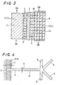
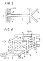
- the plating layer 51 of any metal high in heat conductivity such as copper, silver, aluminum and the like, as shown in FIG. 5 is applied over the porous metallic members 11, 12 in a way varying gradually in thickness across the junction layers 9, 10.
- Gradual change in thickness of the plating layer 51 on the porous metallic members 11, 12 as in FIG. 5 can be made by varying the time it takes for dipping the porous metallic members 11, 12 in a solution containing the desired surface material.
- aluminum coating layer is made on the surfaces of the porous metallic members 11, 12 and then subjected to heat-treatment to precipitate a corundum crystalline of ⁇ -alumina structure, which helps enhance the porous metallic members 11, 12 in mechanical strength and corrosion resistance, and also form much roughness including voids or cells over the outside surfaces of the porous metallic members 11, 12 to provide a largely extended surface area, thereby improving the effectiveness of the heat exchanger.
- FIG. 4 shows schematically a unit area to imagine a stem 5 joined with the partition wall 2, along with twigs 6 branching out from the stem 5 of the porous metallic member 12 in the colder area 8.
- the stem 5 of the porous metallic member 12 comes into engagement with the partition wall 2 in a way buried in a depth L more than a diameter D of the stem 5 in cross section.
- the porous metallic members 11, 12 come into joining at their many stems 5 together with the partition wall 2 through the junction layers 9, 10.
- Many twigs 6, as shown in FIG. 6 get entangled and intersected with each other to leave clearances among them, which provide open-cells 14 to make sure of smooth flow of fluids GA, GB.
- the hotter area 7 helps provide a largely extended heat-extracting surface area making contact with the hot fluid to transmit heat energy from the fluid to the partition wall 2 while the colder area 8 provides a heat-emitting contact area with the cold fluid, which is largely extended enough to make certain of smooth transmission of heat from the partition wall 2 to the cold fluid.
- the heat exchanger of the present invention is suited, for example, for a fuel-reforming system 15 as in FIG. 7 .
- the fuel-reforming system 15 includes a pair of heat exchanger units 16, 17, which are equal in construction with one another and contained in an enclosure 18.
- the two heat exchanger units 16, 17, one for reforming a natural gas and the other for capturing CO 2 gas, work sequentially, alternatively to pyrolyze the natural gas with heat energy of exhaust gases in the presence of CO 2 gas.
- the two heat exchanger units 16, 17 are separated from one another through a thermal isolation layer 19.
- the heat exchanger units 16, 17 are each made in a layered construction where there are provided the hotter area 7 to allow the exhaust gases to flow through there, the colder area 8 for the natural gas, and the partition wall 2 interposed between the hotter area 7 and the colder area 8 to separate them from one another.
- the colder area 8 is filled with the porous metallic member 12, on the surface of which a catalyst layer 13 is distributed to promote the pyrolysis of, for example the natural gas flowing through the colder area 8.
- the hotter area 7 has the porous metallic member 11 therein, which is coated with any absorbent including zeolite, lithium zirconate, and so on to recover CO 2 gas from, for example the low-temperature exhaust gases. It will be understood that the captured CO 2 gas will be used for the pyrolysis of natural gas.
- the fuel-reforming system 15 is, for example, arranged downstream of an exhaust pipe of an engine to convert the natural gas into the reformed fuel in the presence of any catalyst by using the heat energy reclaimed from the exhaust gases.
- the fuel-reforming system 15 is installed on a turning shaft in any housing with the enclosure 18 being made with gas lines opened to other systems.
- the enclosure 18 is divided into the two heat exchanger units 16 and 17, which are each separated into the hotter area 7 and the colder area 8, which are isolated from one another by means of the partition wall 2.
- the high-temperature exhaust gases flows into the hotter area 7 at an upstream ingress, followed by passing through the hotter area 7 and leaving the area 7 at a downstream egress.
- the natural gas is charged along with air and vapor at an upstream ingress into the colder area 8 in which the catalyst is distributed.
- the natural gas is reformed in the presence of the catalyst and the reformed fuel leaves the colder area 8 at a downstream egress.
- the CO 2 gas needed for pyrolysis of the natural gas is captured out of the low-temperature exhaust gases in absorptive reclamation on the porous metallic member 12.
- the high-temperature exhaust gases are first led through the porous metallic member 11 in the hotter area 7 of any one heat exchanger unit 16, where the hotter exhaust gases results in losing somewhat heat energy, getting a low-temperature exhaust gases.
- the resultant exhaust gases at low-temperature is then introduced into the porous metallic member 12 in the colder area 8 of other heat exchanger unit 17, where the CO 2 gas is absorbed by zeolite and/or by reaction with lithium zirconate. Thereafter, the enclosure 18 makes a half turn.
- the porous metallic body 1 filling in both the hotter and colder areas 7, 8 can emit radiation heat, helping improve the effectiveness of the heat exchanger, use the heat energy stored in the exhaust gases to rearrange the natural gas in properties, thereby converting major component: CH 4 in the natural gas into H 2 and CO.
- the reclaiming of CO 2 gas from the exhaust gases preparatory to the reforming of the natural gas makes it possible to avail the hotter exhaust gases to alter the properties of natural gas in the presence of CO 2 .
- the turbo-generator system includes the provision of a steam turbine improved in possible efficiency to convert heat energy in an exhaust gases from any heat source or engine 20 into either electric or kinetic energy.
- an exhaust turbine 21 needs to be curbed moderately in turbine inlet pressure to relieve the engine 20 from loss of power, which might occur because the engine 20 is exposed to any excess load in exhaust phase thereof.
- a first heat exchanger unit 24 to convert the heat energy stored in the exhaust gases into steam power of elevated stem pressure to drive a steam turbine 22.
- a condenser 25 of heat exchanger is installed at a steam turbine outlet side. In the condenser 25, the steam having left the steam turbine 22 is reduced down in temperature and pressure, for example, below 0.05 kg/cm 2 , thus transformed to a liquid state. This helps improve the efficiency of the steam turbine 22.
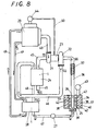
- the turbo-generator system includes the exhaust turbine 21 extracting energy from exhaust gases EG exhaled out of the heat source 20 through an exhaust line 45, a first heat exchanger unit 24 installed with the porous metallic body 1 to generate high-temperature steam by the remaining energy in the exhaust gases EG leaving the exhaust turbine 21, the steam turbine 22 extracting energy from a high-temperature steam SG generated in the first heat exchanger unit 24 and fed through a steam line 46, and an electric generator 23 driven with the exhaust turbine 21 and the steam turbine 22, which are connected to a rotor shaft of the generator 23 at opposite ends.
- the turbo-generator system moreover, includes the condenser 25 for removing heat from a steam SG discharged out of the steam turbine 25 to reduce the steam to a liquid, the condenser being comprised of a porous metallic material surrounding around a tubing that allows the steam to pass through there, a pump 27 to feed the water W produced in the condenser 25 into the first heat exchanger unit 24, and a second heat exchanger unit 28 installed between the pump 27 and the first heat exchanger unit 24 to convert the water W forced through the pump 27 into a steam by using a hotter oil O recirculating through the heat source 20.
- Rankine cycle is mainly composed of the first heat exchanger unit 34, the steam turbine 22, the pump 27 and the second heat exchanger unit 28.
- the first heat exchanger unit 24, as illustrated in FIG. 9 has an outer cylinder 29 filled with a porous metallic member 31 where exhaust gases EG are allowed to pass through there, an inner cylinder 30 nested in the outside cylinder 29 and packed inside with a porous metallic member 32 where a steam SG is allowed to flow through there, and a partition wall 33 to isolate the inside of the outer cylinder 29 from the inside of the inner cylinder 30, the porous metallic members 31, 32 being joined with the opposite sides of the partition wall 33 through many stems of the porous members.
- the partition wall 33 is constituted with the inner cylinder 30.
- porous metallic members 31, 32 lying on opposite sides of the partition wall 33, one to each side, are integrally merged together with the associated surfaces of the partition wall 33 by sintering process of junction layers that are of a paste of joining material kneaded with any powdery metal and buried in the porous metallic members 31, 32.
- a heat insulator 41 to keep the exhaust gases EG against losing heat energy by radiation.
- open-cellular material for the porous metallic member 31 installed inside the outer cylinder 29 is higher in porosity than another open-cellular material for the porous metallic member 32 enclosed in the inner cylinder 30 to make certain of smooth flow of the exhaust gases to thereby keep the engine 20 against any loss that might be otherwise caused by undue back pressure.
- the inner cylinder 30 nests therein a center wall 35 tapered in a fashion that the flow passage for the stream SG is made smaller in cross sectional area at the side of an egress 56 than an ingress 55 to get the velocity of the stream SG faster at the egress 56, increasing Reynolds' number, thereby raising the heat transfer rate.
- the steam line 46 communicated with the egress 56 of the inner cylinder 30 is designed in a way becoming equal in cross section with the egress 56. With this design consideration, the steam SG having increased in velocity during flowing though the inner cylinder 30 will be kept against getting reduced with expansion after the steam SG has left the egress 56 into the steam line 46.
- the taper may be turned upside down to allow the steam SG flowing along the inside of the tapered wall, not shown, and communicating into the steam line 46.
- the steam SG is wet steam and therefore a nozzle 52 is installed in the steam line 48 at the inlet side of the first heat exchanger unit 24 to deliver atomized water jetting out of spray orifices 53 of the nozzle 52 to elevate the heat-transfer efficiency of the first heat exchanger unit 24.
- a porous metallic member 37 is arranged in the steam conduit 36 midway between the steam turbine 22 and the condenser 25 to cool down the steam SG leaving the steam turbine 22.
- the condenser 25 is comprised of an inside liquid chamber 39 having a porous metallic member 34 therein, an outside chamber 40 for cooling gas or liquid in which a porous metallic member 57 is installed, a partition wall 38 separating the inside and outside chamber 39, 40 from one another, and a steam passage 26 extending in the liquid chamber 39 to deliver the steam SG leaving the steam turbine 22 into the liquid chamber 39.
- the porous metallic member 34 in the liquid chamber 39 of the condenser 25 is made up of a plurality of multistage porous metallic sheets 42, which are penetrated with the steam passage 26 at the center thereof and joined with the partition wall 38 along the periphery thereof.
- the steam SG discharged out of the steam passage 26 into the liquid chamber 39, where the steam SG passes through the porous metallic sheets 42 with losing the remaining energy in the steam, once sufficient heat is eliminated, liquefaction occurs.
- the porous metallic member 57 surrounding around the partition wall 38 is arranged to extend the heat-transfer surface coming in contact with the cooling gas or liquid flowing through the outside chamber 40.
- the condenser 25 to cool down the steam SG leaving the steam turbine 22 is made in either an air-cooled system where air is forced into the outside chamber 40 by a blower 43 or a water-cooled system where cooling water is forced to pass through there.
- the porous metallic member 34 installed in the liquid chamber 39 is made of porous material of nickel coated with any corrosion resisting metal including silver, copper, aluminum, and so on, while the another porous metallic member 57 in the outside chamber 40 for cooling air or liquid is made of nickel-based porous metallic material coated with aluminum, and so on.
- a rotor shaft surrounded with a permanent-magnet rotor of the generator 23 is flanked with the steam turbine 22 and the exhaust turbine 21, one to each flank.
- Electric power produced by the generator 23 is partially supplied to a motor 44 through a conductor 50 to drive a compressor to force air into the heat source 20.
- the electric power is in part consumed to drive the motor 44 to spin a drive shaft and a crankshaft to start the engine.
- the exhaust gas and steam energies rotate the rotor shaft, torque of which is reclaimed in the electric power through generator 23.
- the second heat exchanger unit 28 cools down oil heated in recirculating through the engine 20 while converts the water W in Rankine cycle into the steam SG.
- the heated oil 0 including engine oil, lubricating oil, and so on recirculating through the engine 20 is fed into the second heat exchanger unit 28 through a hotter oil line 49, while a cooled oil 0 is fed back to the engine 20 through a colder oil line 49.
- the water W discharged out of the pump 27 is delivered through a water line 47 as a cooling medium into the second heat exchanger unit 28 where the water W is heated to be converted into a low-temperature steam that is in turn supplied through a steam line 48 into the first heat exchanger unit 24, where the low-temperature steam is boosted in temperature by the transfer of heat from the hot exhaust gases EG, and the resultant high-temperature steam SG is delivered into the steam turbine 22 through a hot steam line 46.
- FIGS. 10 and 11 there is shown a preferred embodiment of a fuel-reforming system 15 having incorporated with the heat exchanger of the present invention.
- the fuel-reforming system 15 includes valve means to control the sequential flows of exhaust gases, steam, natural gas fuel and air: an exhaust valve 86, a steam valve 82, a natural gas valve 83 and an air valve 85.
- the fuel-reforming system 15 further includes a cylindrical shell 61 having a plurality of inlet ports 72 at any one of axially opposite ends thereof and a plurality of outlet ports 73 at the other end, and an circular rotary vessel 62 supported for rotation in the cylindrical shell 61 and provided therein with radial partition plates 69 (corresponding the partition wall 2 isolating the hotter and colder areas 7 and 8 from one another), which are positioned at circular intervals to form compartments 75 juxtaposed in circular direction.
- the inlet ports 72 of the cylindrical shell 61 are communicated hermetically through sealing members 79 to, respectively, an exhaust line 64, a steam line 65, a natural gas intake line 66 and an air intake line 84.
- the outlet ports 73 of the cylindrical shell 61 are communicated hermetically through other sealing members 79 to, respectively, another exhaust line 64, another steam line 65, a reformed product delivery line 70 and another air intake line 84.
- the reformed product delivery line 70 and another air intake line 84 are merged into a single line that is communicated with a suction line 80.
- the natural gas intake line 6 lies in lengthwise alignment with the reformed product delivery line 70.
- the compartments 75 in the rotary vessel 62 have contained therein porous metallic bodies 63, one to each compartment, which have the function to alter the properties of natural gas.
- the rotary vessel 62 is fixed to a turning shaft 74 that is supported in the shell 61 for rotation through bearings 76.
- the rotary vessel 62 is made on one axially end thereof with ingress openings allowed to come in alignment with the inlet ports 72 in the shell 61 while on the other end thereof with egress openings 68 allowed to come in alignment with the outlet ports 73 in the shell 61.
- Fuel line is made up of the natural gas intake line 66 connected to the associated inlet port 72 in the shell 61 and the reformed product delivery line 70 opened to the associated outlet port 73 in the shell 61, the natural gas intake line 66 and the reformed product delivery line 70 being positioned in a way lying in axial alignment with one another.
- the rotary vessel 62 is enclosed in the shell 61 with a vacuum space 78 being left between them, and supported on a base 77 for rotation through bearings 76.
- the rotary vessel 62 driven in circular direction by means of a motor 71 that is controlled with commands sent from a controller 60.
- the porous metallic body 63 is composed of a metal including Ni, Cr, Fe, and so on.
- the porous metallic body 63 is coated over the overall surface thereof with alumina over which powdery zeolite is applied to absorb CO 2 gas from the exhaust gases.
- a catalyst layer including Pt, Ru, Ni, Pd, Al 2 O 3 , and so on to promote the thermal reforming of the natural gas into the products of H 2 and CO.
- the motor 71 gets the rotary vessel 62 starting to rotate, coming to rest, turning in intermittent manner, and turning with variable rpm.
- the exhaust gases are introduced through the exhaust line 64 into the compartment 75 in the rotary vessel 62 in which the CO 2 gas is absorbed by the zeolite applied on the surface of the porous metallic body 63.
- the steam produced with heat energy in the exhaust gases is led through the steam line 65 into the compartment 75 to thereby expel the exhaust gases containing oxygen therein out of the compartment 75.
- Natural gas is then charged through the natural gas line 66 into the compartment 75 where the reaction of natural gas with CO 2 absorbed by zeolite and/or activated carbon is carried out in the presence of steam to reform the natural gas into the product of CO and H 2 .
- the rotary vessel 62 is formed in, for example hollow cylinder such as circular cylinder.
- the rotary vessel 62 is also provided therein with radial partition plates 69 to form the compartments 75 defining rooms 81 in which are disposed porous metallic bodies 63, one to each room.
- the ingress openings 67 and the egress openings 68 formed in the rotary vessel 62 pass successively across the inlet and outlet ports 72 and 73 in the shell 61, respectively, which are communicated with the exhaust line 64, steam line 65, natural gas line 66 and the air intake line 73.
- the controller 60 is provided to apply the commands to the motor 71 to control the turning operation of the rotary vessel 62 so as to keep the rotary vessel 62 at the optimal operating condition.
- the motor 71 gets the rotary vessel 62 starting to rotate, coming to rest, turning in intermittent manner, and turning with variable rpm.
- the exhaust gases are introduced through the exhaust line 64 into the compartment 75 in the rotary vessel 62 in which the CO 2 gas is absorbed by the zeolite and/or activated carbon on the surface of the porous metallic body 63. Subsequently, the steam produced with heat energy in the exhaust gases is charged into the compartment 75 to thereby expel the remaining O 2 out of the compartment 75.
- There natural gas is fed into the compartment 75 where CH 4 in the natural gas is converted into the reformed fuel of CO and H 2 in the presence of CO 2 absorbed by zeolite and/or activated carbon, while the reaction of CH 4 with H 2 O is carried out to obtain the reformed fuel of CO and H 2 . All the natural gas is converted into the reformed fuel of CO and H 2 .
- the reformed fuel is fed, along with air introduced through the air intake line 84 into the compartment 75, through the air intake line 80 and then an air intake manifold into the engine.
- the fuel-reforming system 15 can be made in a facilitated construction as shown in FIGS. 12 and 13 , in which the steam line 65 is closed at the outlet side thereof to get the heat energy in the steam consumed completely to reform natural gas (the reaction of the reaction of CH 4 with H 2 O is carried out to convert the natural gas into the reformed fuel of CO and H 2 ).
- the inlet ports 72 of the cylindrical shell 61 are communicated hermetically through sealing members 79 to, respectively, an exhaust line 64, a natural gas intake line 66, a steam line 65 and an air intake line 84.
- the outlet ports 73 of the cylindrical shell 61 are communicated hermetically through other sealing members 79 to, respectively, another exhaust line 64, a reformed product delivery line 70 and another air intake line 84.
- valve means to control sequential flows of exhaust gases, steam, natural gas fuel and air that is, the exhaust valve 86, natural gas valve 83, steam valve 82 and the air valve 85).
- the fuel-reforming system 15 of facilitated type further includes the motor 71 connected to the rotary vessel 62 to get the rotary vessel 62 starting to turn, coming to rest, turning in intermittent manner, and turning with variable rpm depending on the commands issued from the controller 60.
- the exhaust gases are introduced through the exhaust line 64 into the compartment 75 in the rotary vessel 62 in which the CO 2 gas is absorbed by the zeolite and/or activated carbon on the surface of the porous metallic body 63. Subsequently, natural gas is charged into the compartment 75 in which the reaction of CH 4 with O 2 in the exhaust gases is carried out to convert them into CO and H 2 while the reaction of CO 2 with CH 4 is carried out to convert them into the reformed fuel of CO and H 2 .
- the steam generated with heat energy stored in the exhaust gases is introduced through the steam line 65 into the compartment 75 where the remaining CH 4 is converted in the presence of steam (H 2 O) into the reformed fuel of CO and H 2 .
- steam H 2 O
- all the natural gas is completely converted into the reformed fuel of CO and H 2 .
- the reformed fuel is fed, along with air introduced through the air intake line 84 into the compartment 75, through the air intake line 80 and then an air intake manifold into the engine.
Landscapes
- Engineering & Computer Science (AREA)
- General Engineering & Computer Science (AREA)
- Physics & Mathematics (AREA)
- Thermal Sciences (AREA)
- Mechanical Engineering (AREA)
- Chemical & Material Sciences (AREA)
- Crystallography & Structural Chemistry (AREA)
- Dispersion Chemistry (AREA)
- Heat-Exchange Devices With Radiators And Conduit Assemblies (AREA)
- Manufacture And Refinement Of Metals (AREA)
- Hydrogen, Water And Hydrids (AREA)
- Physical Or Chemical Processes And Apparatus (AREA)
- Powder Metallurgy (AREA)
Claims (25)
- Echangeur de chaleur dans lequel de la chaleur est transférée d'une zone d'extraction de chaleur (7) où un fluide est amené à s'écouler à travers la zone d'extraction de chaleur jusqu'à une zone d'émission de chaleur (8) où un autre fluide, différent par sa température du fluide, est amené à s'écouler à travers la zone d'émission de chaleur,
dans lequel une paroi (2) est fournie pour séparer les zones (7, 8) l'une de l'autre, et des métaux poreux (11, 12) sont fournis dans les zones (7, 8), à raison d'un à chaque zone, les métaux poreux (1) étant chacun muni sur une de leurs surfaces d'une couche de jonction (9, 10) de matière de jonction pâteuse malaxée avec un métal pulvérisé, les métaux poreux (1) étant chacun fusionnés avec la paroi (2) par fusion de la couche de jonction associée (9, 10) pour effectuer un certain transfert de chaleur entre la paroi (2) et les métaux poreux (1), et
caractérisé en ce que les couches de jonction (9, 10) sont enfouies dans les métaux poreux (11) de manière à venir en contact avec les faces opposées de la paroi (2), à raison d'une à chaque face, et la première couche de jonction (9) a une propriété de grande résistance à la chaleur et la seconde couche de jonction (10) a une température de fusion inférieure de plus de 100°C à celle de la première, la première couche de jonction (9) étant constituée d'une matière de jonction ayant une température de fusion supérieure à celle de la seconde couche de jonction (10). - Echangeur de chaleur ayant une structure suivant la revendication 1, dans lequel les métaux poreux (1) sont constitués d'au moins un métal choisi entre le nickel, un alliage nickel-chrome, le cuivre et l'aluminium, tandis que la paroi (2) est constituée d'un alliage de cuivre et de n'importe lequel des métaux consistant en le nickel et un alliage nickel-chrome, et le métal pulvérisé est constitué d'un métal thermorésistant ayant une conductivité thermique supérieure, choisi entre l'argent, le nickel, le cuivre et le zinc.
- Echangeur de chaleur ayant la structure suivant l'une quelconque des revendications 1 et 2, dans lequel les métaux poreux (12) comportent une tige (5) tandis que les couches de jonction (9, 10) sont liées aux métaux poreux (12) de telle sorte que la tige (5) soit enfouie dans la couche de jonction associée à une profondeur non inférieure à un diamètre (D) de la tige (5) en section transversale ou bien entourée par la couche de jonction (9, 10) suivant une forme conique.
- Echangeur de chaleur ayant la structure suivant l'une quelconque des revendications précédentes, dans lequel au moins un métal de forte conductivité thermique choisi entre le cuivre, l'aluminium et l'argent est appliqué sous forme de revêtement sur la surface des métaux poreux (11) par n'importe lequel des procédés consistant en le placage, l'immersion et l'évaporation sous vide.
- Echangeur de chaleur ayant la structure suivant l'une quelconque des revendications précédentes, dans lequel les métaux poreux (11, 12) sont chacun munis d'une rainure sur une de leur surface opposée à la surface liée à la couche de jonction associée, la rainure s'étendant le long du trajet d'écoulement du fluide.
- Echangeur de chaleur ayant la structure suivant l'une quelconque des revendications précédentes, dans lequel les métaux poreux (12) comportent, par application à leur surface, un revêtement céramique d'alumine ou de zircone sur lequel est distribué au moins un catalyseur choisi entre le platine, le vanadium, le rhodium, le ruthénium et l'oxyde de cérium.
- Echangeur de chaleur ayant une structure suivant l'une quelconque des revendications précédentes, dans lequel les métaux poreux (11, 12) sont munis sur leur surface d'un revêtement constitué d'une couche de placage (51) d'au moins une matière ayant une forte conductivité thermique choisie entre le cuivre, l'argent et l'aluminium, la couche de placage (51) ayant une épaisseur variant progressivement à travers la couche de jonction (9, 10).
- Echangeur de chaleur ayant une structure suivant la revendication 7, dans lequel la variation progressive d'épaisseur de la couche de placage (51) sur la surface des métaux poreux (11, 12) est réalisée en faisant varier le temps nécessaire pour l'immersion des métaux poreux (11, 12) dans le bain de placage.
- Echangeur de chaleur ayant une structure suivant la revendication 1, dans lequel une couche d'aluminium de revêtement est formée sur les surfaces des métaux poreux (11, 12) et est ensuite soumise à un traitement thermique pour la précipitation d'une structure d'alpha-alumine.
- Echangeur de chaleur ayant une structure suivant la revendication 1, qui est appliqué à un système de turbo-générateur comprenant une turbine d'échappement (21) extrayant de l'énergie de gaz d'échappement (EG) évacués par la source de chaleur d'un moteur (20) ou d'un brûleur, un premier échangeur de chaleur (24) pour engendrer de la vapeur d'eau à haute température par l'énergie restante dans les gaz d'échappement (EG) quittant la turbine d'échappement (21), une turbine à vapeur (22) extrayant l'énergie de vapeur d'eau à haute température engendrée dans le premier échangeur de chaleur (24), un générateur électrique (23) ayant un arbre de rotor connecté à la turbine d'échappement (21) et à la turbine à vapeur (22) à leurs extrémités axialement opposées, un condenseur (25) pour évacuer la chaleur de la vapeur d'eau (SG) déchargée de la turbine à vapeur (22) pour réduire la vapeur d'eau (SG) en un liquide, le condenseur (25) étant constitué d'un métal poreux (34), installé sur une tubulure (26) qui permet à la vapeur d'eau (SG) de passer à travers celle-ci, une pompe (27) pour amener l'eau (W) produite dans le condenseur (25) dans le premier échangeur de chaleur (24), et un second échangeur de chaleur (28) installé entre la pompe (27) et la première unité d'échangeur de chaleur (24) pour convertir l'eau (W) passée à force à travers la pompe (27) en de la vapeur d'eau en utilisant une huile chaude (O) recirculant à travers la source de chaleur (20).
- Echangeur de chaleur ayant une structure suivant la revendication 10, dans lequel la première unité d'échangeur de chaleur (24) comporte un cylindre extérieur (29) rempli d'un métal poreux (31) où les gaz d'échappement (EG) sont amenés à passer à travers le métal poreux (31), et un cylindre intérieur (30) emboîté dans le cylindre extérieur (29) et garni intérieurement d'un métal poreux (32) où de la valeur d'eau (SG) est amenée à s'écouler à travers le métal poreux (32), le cylindre intérieur (30) étant joint sur sa surface extérieure au métal poreux (31) à l'intérieur du cylindre extérieur (29) tandis que, sur sa surface intérieure, il est joint au métal poreux (32) à l'intérieur du cylindre intérieur (30) par fusion du métal de telle sorte que le cylindre intérieur (30) serve de paroi isolant l'un de l'autre les métaux poreux (31 à 32) sur ses surfaces opposées.
- Echangeur de chaleur ayant une structure suivant la revendication 11, dans lequel les métaux poreux (31, 32) sur les surfaces opposées de la paroi (33) dans la première unité d'échangeur de chaleur (24) sont joints à la paroi (33) par fusion des couches de jonction de matière de jonction pâteuse enfouie dans les métaux poreux (31, 32).
- Echangeur de chaleur ayant une structure suivant l'une quelconque des revendications 11 et 12, dans lequel un isolant thermique (41) entoure une périphérie du cylindre extérieur (29), et le métal poreux (31) installé à l'intérieur du cylindre extérieur (29) a une porosité supérieure à celle du métal poreux (32) enfermée dans le cylindre intérieur (30).
- Echangeur de chaleur ayant une structure suivant l'une quelconque des revendications 11 à 13, dans lequel le cylindre intérieur (30) est constitué de telle sorte qu'un passage d'écoulement de la vapeur d'eau (SG) soit réduit en surface en section transversale au niveau de ses sorties (56), par rapport à une de ses entrées (55), pour parvenir à une plus grande vitesse de la vapeur d'eau à la sortie (56) .
- Echangeur de chaleur ayant une structure suivant l'une quelconque des revendications 10 à 14, dans lequel un métal poreux (37) ou une ailette est installée sur un conduit de vapeur (46) à mi-distance entre la turbine à vapeur (22) et le condenseur (25) pour refroidir la vapeur d'eau (SG) quittant la turbine à vapeur (22).
- Echangeur de chaleur ayant une structure suivant l'une quelconque des revendications 10 à 15, dans lequel le condenseur (25) est constitué d'une chambre de liquide intérieure (39) comportant un métal poreux (34), d'une chambre extérieure (40) pour le refroidissement d'un gaz ou d'un liquide, dans laquelle un métal poreux (57) est installé, d'une paroi (38) séparant la chambre intérieure et la chambre extérieure (39, 40) l'une de l'autre, et d'un passage de vapeur d'eau (26) s'étendant dans la chambre de liquide (39) pour délivrer la vapeur d'eau (SG) quittant la turbine à vapeur (22) dans la chambre de liquide (39).
- Echangeur de chaleur ayant une structure suivant l'une quelconque des revendications 10 à 16, dans lequel le métal poreux (34) dans la chambre de liquide (39) du condenseur (25) est constitué d'une pluralité de feuilles métalliques à étages multiples (42), qui sont traversées par le passage de vapeur d'eau (26) à leur centre et jointes à la paroi (38) séparant la chambre de liquide (39) du gaz ou du liquide, de telle sorte que la vapeur d'eau (SG) soit déchargée du passage de vapeur d'eau (26) dans la chambre de liquide (39), la vapeur d'eau passant à travers les feuilles métalliques poreuses (42) en perdant l'énergie restante dans la vapeur d'eau (SG).
- Echangeur de chaleur ayant une structure suivant la revendication 17, dans lequel le métal poreux (57) dans la chambre extérieure (40) pour le refroidissement d'un gaz ou d'un liquide est joint à la paroi (38) pour refroidir la vapeur d'eau (SG) déchargée de la turbine à vapeur (22), de telle sorte que le condenseur (25) soit présent dans un système refroidi par air où de l'air est passé à force dans la chambre extérieure (40) par une soufflante (43) ou bien dans un système refroidi par eau dans lequel de l'eau de refroidissement est contrainte à passer à travers celui-ci.
- Echangeur de chaleur ayant une structure suivant l'une quelconque des revendications 10 à 18, dans lequel le métal poreux (34) installé dans la chambre de liquide (39) est constitué d'une matière poreuse formée de nickel revêtu d'au moins un métal résistant à la corrosion comprenant l'argent, le cuivre et l'aluminium, tandis que le métal poreux (57) dans la chambre extérieure (40) pour le refroidissement d'air ou d'un liquide est constitué d'un métal poreux à base de nickel revêtu d'aluminium.
- Echangeur de chaleur ayant une structure suivant l'une quelconque des revendications 10 à 19, dans lequel un arbre de rotor entouré d'un rotor à aimant permanent du générateur (23) est flanqué de la turbine à vapeur (32) et de la turbine d'échappement (21), à raison d'une de chaque côté.
- Echangeur de chaleur ayant une structure suivant l'une quelconque des revendications 10 à 20, dans lequel la puissance électrique produite par le générateur (23) est fournie à un moteur (44) pour faire fonctionner un compresseur afin de faire passer à force de l'air dans la source de chaleur (20) ou bien à un moteur (44) pour faire tourner un vilebrequin du moteur à travers un ondulateur.
- Echangeur de chaleur ayant une structure suivant la revendication 1, qui est appliqué à un système de reformage de carburant (15) installé dans un conduit d'échappement d'un moteur (20) pour convertir un gaz naturel en un carburant reformé constitué de H2 et CO en utilisant l'énergie thermique des gaz d'échappement du moteur où le carburant reformé s'enflamme et brûle.
- Echangeur de chaleur ayant une structure suivant la revendication 22, dans lequel le système de reformage de carburant (15) comporte un moyen d'absorption pour absorber le CO2 des gaz d'échappement, et un moyen de catalyseur pour permettre de convertir le gaz naturel en le carburant reformé, de l'énergie thermique provenant des gaz d'échappement étant ainsi récupérée.
- Echangeur de chaleur ayant une structure suivant la revendication 22, dans lequel le système de reformage du carburant 15 comprend une enveloppe cylindrique (61) ayant des orifices d'admission (72) et des orifices de sortie (73), un récipient rotatif circulaire (62) porté à des fins de rotation dans l'enveloppe cylindrique (61) et muni de plaques de partage radiales (69) pour former des compartiments juxtaposés dans la direction circulaire, des métaux poreux (63) logés dans les compartiments, les métaux poreux (63) portant une matière absorbante et un catalyseur, et le conduit d'échappement (64), le conduit de vapeur (65) et le conduit de gaz naturel (66) sont amenés à communiquer respectivement avec les orifices d'admission et de sortie (72, 73) dans l'enveloppe cylindrique (61).
- Echangeur de chaleur ayant une structure suivant la revendication 22, dans lequel le système de reformage de carburant (15) comprend un moyen de vanne pour commander les écoulements séquentiels des gaz d'échappement provenant du conduit d'échappement (64), de la vapeur d'eau provenant du conduit de vapeur d'eau (65), et du carburant dérivé du gaz naturel provenant du conduit de gaz naturel (66) dans le récipient rotatif (62).
Applications Claiming Priority (4)
| Application Number | Priority Date | Filing Date | Title |
|---|---|---|---|
| JP2002325045 | 2002-11-08 | ||
| JP2002325052 | 2002-11-08 | ||
| JP2002325045A JP2004156881A (ja) | 2002-11-08 | 2002-11-08 | 多孔質金属を用いた熱交換器の構造 |
| JP2002325052A JP4202093B2 (ja) | 2002-11-08 | 2002-11-08 | 金属多孔質部材を有する熱交換器を組み込んだタービン発電システム |
Publications (3)
| Publication Number | Publication Date |
|---|---|
| EP1418397A2 EP1418397A2 (fr) | 2004-05-12 |
| EP1418397A3 EP1418397A3 (fr) | 2005-09-14 |
| EP1418397B1 true EP1418397B1 (fr) | 2009-09-09 |
Family
ID=32109528
Family Applications (1)
| Application Number | Title | Priority Date | Filing Date |
|---|---|---|---|
| EP03257048A Expired - Lifetime EP1418397B1 (fr) | 2002-11-08 | 2003-11-07 | Echangeur de chaleur pour systèmes regenerateurs de carburant et turbo-generateurs |
Country Status (3)
| Country | Link |
|---|---|
| EP (1) | EP1418397B1 (fr) |
| AT (1) | ATE442566T1 (fr) |
| DE (1) | DE60329154D1 (fr) |
Cited By (1)
| Publication number | Priority date | Publication date | Assignee | Title |
|---|---|---|---|---|
| EP4462060A4 (fr) * | 2022-01-07 | 2025-11-26 | Ihi Corp | Structure d'échange de chaleur |
Families Citing this family (3)
| Publication number | Priority date | Publication date | Assignee | Title |
|---|---|---|---|---|
| CN108870798B (zh) * | 2017-05-12 | 2020-07-14 | 浙江大学 | 辐射制冷颗粒和蒸气凝结回收装置 |
| KR102345324B1 (ko) * | 2020-08-28 | 2021-12-31 | 엘지전자 주식회사 | 리니어 압축기 |
| CN119703087B (zh) * | 2024-12-30 | 2025-09-12 | 华中科技大学 | 多孔金属平板的增强设计方法与激光选区熔化成形方法 |
Family Cites Families (6)
| Publication number | Priority date | Publication date | Assignee | Title |
|---|---|---|---|---|
| FR2026088A1 (en) * | 1968-12-13 | 1970-09-11 | Dunlop Co Ltd | Metallic foam heat transfer element |
| US4222434A (en) * | 1978-04-27 | 1980-09-16 | Clyde Robert A | Ceramic sponge heat-exchanger member |
| DE3435319A1 (de) * | 1984-09-26 | 1986-04-03 | Michael 4150 Krefeld Laumen | Katalytischer dampferzeuger |
| JPH10148120A (ja) * | 1996-11-18 | 1998-06-02 | Isuzu Ceramics Kenkyusho:Kk | 給電用エンジンの熱回収装置 |
| JPH116602A (ja) * | 1997-06-13 | 1999-01-12 | Isuzu Ceramics Kenkyusho:Kk | 熱交換器の構造 |
| JP3580091B2 (ja) * | 1997-07-28 | 2004-10-20 | いすゞ自動車株式会社 | ランキンサイクルにおけるコンデンサ |
-
2003
- 2003-11-07 DE DE60329154T patent/DE60329154D1/de not_active Expired - Lifetime
- 2003-11-07 AT AT03257048T patent/ATE442566T1/de not_active IP Right Cessation
- 2003-11-07 EP EP03257048A patent/EP1418397B1/fr not_active Expired - Lifetime
Cited By (1)
| Publication number | Priority date | Publication date | Assignee | Title |
|---|---|---|---|---|
| EP4462060A4 (fr) * | 2022-01-07 | 2025-11-26 | Ihi Corp | Structure d'échange de chaleur |
Also Published As
| Publication number | Publication date |
|---|---|
| ATE442566T1 (de) | 2009-09-15 |
| EP1418397A3 (fr) | 2005-09-14 |
| DE60329154D1 (de) | 2009-10-22 |
| EP1418397A2 (fr) | 2004-05-12 |
Similar Documents
| Publication | Publication Date | Title |
|---|---|---|
| US7059130B2 (en) | Heat exchanger applicable to fuel-reforming system and turbo-generator system | |
| CN110248849B (zh) | 集成式能量转换、传递和存储系统 | |
| KR101720571B1 (ko) | 열전 기반 발전 시스템 및 방법 | |
| RU2353047C2 (ru) | Термоэлектрические системы производства электроэнергии | |
| US20210207527A1 (en) | Ultra-high temperature thermal energy storage system | |
| CN107100736A (zh) | 燃气轮机联合系统 | |
| JP2011094626A (ja) | タービンエンジン冷却のための装置及び方法 | |
| McDonald et al. | Ceramic recuperator and turbine: The key to achieving a 40 percent efficient microturbine | |
| CN115638142A (zh) | 集成式能量转换、传递和存储系统 | |
| US4392351A (en) | Multi-cylinder stirling engine | |
| EP4089273A1 (fr) | Support pour tube d'échangeur de chaleur | |
| EP1418397B1 (fr) | Echangeur de chaleur pour systèmes regenerateurs de carburant et turbo-generateurs | |
| US11231236B2 (en) | Rotary regenerator | |
| EP2384395B1 (fr) | Système de récupération d'énergie pour moteur à combustion interne | |
| JP5955858B2 (ja) | 間接加熱式ガスタービンシステム | |
| CN118167454A (zh) | 一种燃机余热超临界co2循环发电系统及其运行方法 | |
| EP0884550A2 (fr) | Echangeur de chaleur, dispositif d'échange de chaleur pour moteur à gaz | |
| Kawamura et al. | Development of an adiabatic engine installed energy recover turbines and converters of CNG fuel | |
| JP2003240473A (ja) | 熱交換器 | |
| JP4202093B2 (ja) | 金属多孔質部材を有する熱交換器を組み込んだタービン発電システム | |
| JP2005002928A (ja) | ガスタービン高温部品の冷却方法及びそれを利用したガスタービン | |
| JP2022106591A (ja) | 熱回収装置及び熱回収システム | |
| JP2000220977A (ja) | 内燃機関用回転蓄熱式熱交換装置 | |
| JP5986453B2 (ja) | ブレイトンサイクル機関 | |
| JP4777536B2 (ja) | 多孔体熱電発電素子 |
Legal Events
| Date | Code | Title | Description |
|---|---|---|---|
| PUAI | Public reference made under article 153(3) epc to a published international application that has entered the european phase |
Free format text: ORIGINAL CODE: 0009012 |
|
| AK | Designated contracting states |
Kind code of ref document: A2 Designated state(s): AT BE BG CH CY CZ DE DK EE ES FI FR GB GR HU IE IT LI LU MC NL PT RO SE SI SK TR |
|
| AX | Request for extension of the european patent |
Extension state: AL LT LV MK |
|
| PUAL | Search report despatched |
Free format text: ORIGINAL CODE: 0009013 |
|
| AK | Designated contracting states |
Kind code of ref document: A3 Designated state(s): AT BE BG CH CY CZ DE DK EE ES FI FR GB GR HU IE IT LI LU MC NL PT RO SE SI SK TR |
|
| AX | Request for extension of the european patent |
Extension state: AL LT LV MK |
|
| RIC1 | Information provided on ipc code assigned before grant |
Ipc: 7F 28F 13/18 A Ipc: 7F 28F 13/00 B Ipc: 7F 28F 21/08 B |
|
| AKX | Designation fees paid |
Designated state(s): AT BE BG CH CY CZ DE DK EE ES FI FR GB GR HU IE IT LI LU MC NL PT RO SE SI SK TR |
|
| 17P | Request for examination filed |
Effective date: 20060310 |
|
| GRAP | Despatch of communication of intention to grant a patent |
Free format text: ORIGINAL CODE: EPIDOSNIGR1 |
|
| RAP1 | Party data changed (applicant data changed or rights of an application transferred) |
Owner name: SHIP & OCEAN FOUNDATION |
|
| GRAS | Grant fee paid |
Free format text: ORIGINAL CODE: EPIDOSNIGR3 |
|
| GRAA | (expected) grant |
Free format text: ORIGINAL CODE: 0009210 |
|
| AK | Designated contracting states |
Kind code of ref document: B1 Designated state(s): AT BE BG CH CY CZ DE DK EE ES FI FR GB GR HU IE IT LI LU MC NL PT RO SE SI SK TR |
|
| REG | Reference to a national code |
Ref country code: GB Ref legal event code: FG4D |
|
| REG | Reference to a national code |
Ref country code: CH Ref legal event code: EP |
|
| REG | Reference to a national code |
Ref country code: IE Ref legal event code: FG4D |
|
| REF | Corresponds to: |
Ref document number: 60329154 Country of ref document: DE Date of ref document: 20091022 Kind code of ref document: P |
|
| PG25 | Lapsed in a contracting state [announced via postgrant information from national office to epo] |
Ref country code: SE Free format text: LAPSE BECAUSE OF FAILURE TO SUBMIT A TRANSLATION OF THE DESCRIPTION OR TO PAY THE FEE WITHIN THE PRESCRIBED TIME-LIMIT Effective date: 20090909 Ref country code: FI Free format text: LAPSE BECAUSE OF FAILURE TO SUBMIT A TRANSLATION OF THE DESCRIPTION OR TO PAY THE FEE WITHIN THE PRESCRIBED TIME-LIMIT Effective date: 20090909 |
|
| NLV1 | Nl: lapsed or annulled due to failure to fulfill the requirements of art. 29p and 29m of the patents act | ||
| PG25 | Lapsed in a contracting state [announced via postgrant information from national office to epo] |
Ref country code: SI Free format text: LAPSE BECAUSE OF FAILURE TO SUBMIT A TRANSLATION OF THE DESCRIPTION OR TO PAY THE FEE WITHIN THE PRESCRIBED TIME-LIMIT Effective date: 20090909 Ref country code: NL Free format text: LAPSE BECAUSE OF FAILURE TO SUBMIT A TRANSLATION OF THE DESCRIPTION OR TO PAY THE FEE WITHIN THE PRESCRIBED TIME-LIMIT Effective date: 20090909 |
|
| PG25 | Lapsed in a contracting state [announced via postgrant information from national office to epo] |
Ref country code: CY Free format text: LAPSE BECAUSE OF FAILURE TO SUBMIT A TRANSLATION OF THE DESCRIPTION OR TO PAY THE FEE WITHIN THE PRESCRIBED TIME-LIMIT Effective date: 20090909 |
|
| PG25 | Lapsed in a contracting state [announced via postgrant information from national office to epo] |
Ref country code: RO Free format text: LAPSE BECAUSE OF FAILURE TO SUBMIT A TRANSLATION OF THE DESCRIPTION OR TO PAY THE FEE WITHIN THE PRESCRIBED TIME-LIMIT Effective date: 20090909 Ref country code: EE Free format text: LAPSE BECAUSE OF FAILURE TO SUBMIT A TRANSLATION OF THE DESCRIPTION OR TO PAY THE FEE WITHIN THE PRESCRIBED TIME-LIMIT Effective date: 20090909 Ref country code: PT Free format text: LAPSE BECAUSE OF FAILURE TO SUBMIT A TRANSLATION OF THE DESCRIPTION OR TO PAY THE FEE WITHIN THE PRESCRIBED TIME-LIMIT Effective date: 20100111 Ref country code: ES Free format text: LAPSE BECAUSE OF FAILURE TO SUBMIT A TRANSLATION OF THE DESCRIPTION OR TO PAY THE FEE WITHIN THE PRESCRIBED TIME-LIMIT Effective date: 20091220 Ref country code: CZ Free format text: LAPSE BECAUSE OF FAILURE TO SUBMIT A TRANSLATION OF THE DESCRIPTION OR TO PAY THE FEE WITHIN THE PRESCRIBED TIME-LIMIT Effective date: 20090909 |
|
| PG25 | Lapsed in a contracting state [announced via postgrant information from national office to epo] |
Ref country code: SK Free format text: LAPSE BECAUSE OF FAILURE TO SUBMIT A TRANSLATION OF THE DESCRIPTION OR TO PAY THE FEE WITHIN THE PRESCRIBED TIME-LIMIT Effective date: 20090909 |
|
| PG25 | Lapsed in a contracting state [announced via postgrant information from national office to epo] |
Ref country code: AT Free format text: LAPSE BECAUSE OF FAILURE TO SUBMIT A TRANSLATION OF THE DESCRIPTION OR TO PAY THE FEE WITHIN THE PRESCRIBED TIME-LIMIT Effective date: 20090909 Ref country code: BE Free format text: LAPSE BECAUSE OF FAILURE TO SUBMIT A TRANSLATION OF THE DESCRIPTION OR TO PAY THE FEE WITHIN THE PRESCRIBED TIME-LIMIT Effective date: 20090909 Ref country code: MC Free format text: LAPSE BECAUSE OF NON-PAYMENT OF DUE FEES Effective date: 20091130 |
|
| REG | Reference to a national code |
Ref country code: CH Ref legal event code: PL |
|
| PLBE | No opposition filed within time limit |
Free format text: ORIGINAL CODE: 0009261 |
|
| STAA | Information on the status of an ep patent application or granted ep patent |
Free format text: STATUS: NO OPPOSITION FILED WITHIN TIME LIMIT |
|
| PG25 | Lapsed in a contracting state [announced via postgrant information from national office to epo] |
Ref country code: DK Free format text: LAPSE BECAUSE OF FAILURE TO SUBMIT A TRANSLATION OF THE DESCRIPTION OR TO PAY THE FEE WITHIN THE PRESCRIBED TIME-LIMIT Effective date: 20090909 |
|
| 26N | No opposition filed |
Effective date: 20100610 |
|
| REG | Reference to a national code |
Ref country code: FR Ref legal event code: ST Effective date: 20100730 |
|
| PG25 | Lapsed in a contracting state [announced via postgrant information from national office to epo] |
Ref country code: LI Free format text: LAPSE BECAUSE OF NON-PAYMENT OF DUE FEES Effective date: 20091130 Ref country code: FR Free format text: LAPSE BECAUSE OF NON-PAYMENT OF DUE FEES Effective date: 20091130 Ref country code: GR Free format text: LAPSE BECAUSE OF FAILURE TO SUBMIT A TRANSLATION OF THE DESCRIPTION OR TO PAY THE FEE WITHIN THE PRESCRIBED TIME-LIMIT Effective date: 20091210 Ref country code: IE Free format text: LAPSE BECAUSE OF NON-PAYMENT OF DUE FEES Effective date: 20091107 Ref country code: CH Free format text: LAPSE BECAUSE OF NON-PAYMENT OF DUE FEES Effective date: 20091130 |
|
| PG25 | Lapsed in a contracting state [announced via postgrant information from national office to epo] |
Ref country code: IT Free format text: LAPSE BECAUSE OF FAILURE TO SUBMIT A TRANSLATION OF THE DESCRIPTION OR TO PAY THE FEE WITHIN THE PRESCRIBED TIME-LIMIT Effective date: 20090909 Ref country code: BG Free format text: LAPSE BECAUSE OF FAILURE TO SUBMIT A TRANSLATION OF THE DESCRIPTION OR TO PAY THE FEE WITHIN THE PRESCRIBED TIME-LIMIT Effective date: 20091130 |
|
| PG25 | Lapsed in a contracting state [announced via postgrant information from national office to epo] |
Ref country code: LU Free format text: LAPSE BECAUSE OF NON-PAYMENT OF DUE FEES Effective date: 20091107 |
|
| PG25 | Lapsed in a contracting state [announced via postgrant information from national office to epo] |
Ref country code: HU Free format text: LAPSE BECAUSE OF FAILURE TO SUBMIT A TRANSLATION OF THE DESCRIPTION OR TO PAY THE FEE WITHIN THE PRESCRIBED TIME-LIMIT Effective date: 20100310 |
|
| PG25 | Lapsed in a contracting state [announced via postgrant information from national office to epo] |
Ref country code: TR Free format text: LAPSE BECAUSE OF FAILURE TO SUBMIT A TRANSLATION OF THE DESCRIPTION OR TO PAY THE FEE WITHIN THE PRESCRIBED TIME-LIMIT Effective date: 20090909 |
|
| PGFP | Annual fee paid to national office [announced via postgrant information from national office to epo] |
Ref country code: GB Payment date: 20140912 Year of fee payment: 12 |
|
| PGFP | Annual fee paid to national office [announced via postgrant information from national office to epo] |
Ref country code: DE Payment date: 20141105 Year of fee payment: 12 |
|
| REG | Reference to a national code |
Ref country code: DE Ref legal event code: R119 Ref document number: 60329154 Country of ref document: DE |
|
| GBPC | Gb: european patent ceased through non-payment of renewal fee |
Effective date: 20151107 |
|
| PG25 | Lapsed in a contracting state [announced via postgrant information from national office to epo] |
Ref country code: GB Free format text: LAPSE BECAUSE OF NON-PAYMENT OF DUE FEES Effective date: 20151107 Ref country code: DE Free format text: LAPSE BECAUSE OF NON-PAYMENT OF DUE FEES Effective date: 20160601 |