EP1418423B1 - Gerät und Methode zur zerstörungsfreien Prüfung von Flugzeugstrukturen - Google Patents
Gerät und Methode zur zerstörungsfreien Prüfung von Flugzeugstrukturen Download PDFInfo
- Publication number
- EP1418423B1 EP1418423B1 EP03078190A EP03078190A EP1418423B1 EP 1418423 B1 EP1418423 B1 EP 1418423B1 EP 03078190 A EP03078190 A EP 03078190A EP 03078190 A EP03078190 A EP 03078190A EP 1418423 B1 EP1418423 B1 EP 1418423B1
- Authority
- EP
- European Patent Office
- Prior art keywords
- sensor
- actuating member
- workpiece
- cam
- automated
- Prior art date
- Legal status (The legal status is an assumption and is not a legal conclusion. Google has not performed a legal analysis and makes no representation as to the accuracy of the status listed.)
- Expired - Lifetime
Links
- 238000000034 method Methods 0.000 title claims description 35
- 230000001066 destructive effect Effects 0.000 title claims description 7
- 238000007689 inspection Methods 0.000 title description 16
- 238000012360 testing method Methods 0.000 claims description 4
- 239000000463 material Substances 0.000 description 9
- 238000012545 processing Methods 0.000 description 9
- 239000000853 adhesive Substances 0.000 description 8
- 230000001070 adhesive effect Effects 0.000 description 8
- 150000001875 compounds Chemical class 0.000 description 6
- 238000009659 non-destructive testing Methods 0.000 description 5
- 230000000717 retained effect Effects 0.000 description 5
- 239000004677 Nylon Substances 0.000 description 4
- 238000001514 detection method Methods 0.000 description 4
- 229920001778 nylon Polymers 0.000 description 4
- 238000004891 communication Methods 0.000 description 3
- 230000007797 corrosion Effects 0.000 description 3
- 238000005260 corrosion Methods 0.000 description 3
- 230000006378 damage Effects 0.000 description 3
- 230000007547 defect Effects 0.000 description 3
- 239000007769 metal material Substances 0.000 description 3
- 239000004033 plastic Substances 0.000 description 3
- 239000004593 Epoxy Substances 0.000 description 2
- 239000004568 cement Substances 0.000 description 2
- 239000002131 composite material Substances 0.000 description 2
- 230000009977 dual effect Effects 0.000 description 2
- 239000012811 non-conductive material Substances 0.000 description 2
- 239000012858 resilient material Substances 0.000 description 2
- 239000000523 sample Substances 0.000 description 2
- 208000012514 Cumulative Trauma disease Diseases 0.000 description 1
- 229910000831 Steel Inorganic materials 0.000 description 1
- 230000003213 activating effect Effects 0.000 description 1
- XAGFODPZIPBFFR-UHFFFAOYSA-N aluminium Chemical compound [Al] XAGFODPZIPBFFR-UHFFFAOYSA-N 0.000 description 1
- 229910052782 aluminium Inorganic materials 0.000 description 1
- 238000005336 cracking Methods 0.000 description 1
- 238000013461 design Methods 0.000 description 1
- 230000005802 health problem Effects 0.000 description 1
- 230000003252 repetitive effect Effects 0.000 description 1
- 230000002441 reversible effect Effects 0.000 description 1
- 239000010959 steel Substances 0.000 description 1
Images

Classifications
-
- G—PHYSICS
- G01—MEASURING; TESTING
- G01N—INVESTIGATING OR ANALYSING MATERIALS BY DETERMINING THEIR CHEMICAL OR PHYSICAL PROPERTIES
- G01N27/00—Investigating or analysing materials by the use of electric, electrochemical, or magnetic means
- G01N27/72—Investigating or analysing materials by the use of electric, electrochemical, or magnetic means by investigating magnetic variables
- G01N27/82—Investigating or analysing materials by the use of electric, electrochemical, or magnetic means by investigating magnetic variables for investigating the presence of flaws
- G01N27/90—Investigating or analysing materials by the use of electric, electrochemical, or magnetic means by investigating magnetic variables for investigating the presence of flaws using eddy currents
- G01N27/9013—Arrangements for scanning
- G01N27/902—Arrangements for scanning by moving the sensors
Definitions
- This invention relates to techniques for the non-destructive testing of structures, and, in particular, to economical and time-conserving techniques for moving one or more non-destructive sensors relative to the portion of the structure to be tested.
- Non-destructive testing of structures involves thoroughly examining a structure without harming the structure or requiring significant disassembly of the structure.
- Non-destructive testing is advantageous for many applications in which a thorough inspection of the exterior and/or interior of a structure is required.
- non-destructive testing is commonly utilized in the aircraft industry to inspect aircraft structures for any type of internal or external damage to the structure.
- Metallic aircraft structures are typically inspected for corrosion and/or cracking, particularly near fasteners in the structure.
- Composite structures are typically inspected for any type of damage occurring anywhere on or within the composite material.
- sensors may be utilized to perform non-destructive testing.
- One or more sensors may move over the portion of the structure to be examined, and receive data regarding the structure.
- a pulse-echo, thru-transmission, or shear wave sensor may be utilized to obtain ultrasonic data, such as thickness gauging, detection of laminar defects and porosity, and/or crack detection in the structure.
- Resonance, pitch/catch or mechanical impedance sensors may be utilized to provide indications of voids or porosity, such as in adhesive bondlines of the structure.
- single and dual current eddy current sensors impart and detect eddy currents within a structure so as to identify cracks and/or corrosion, particularly in metallic or other conductive structures.
- the data acquired by the sensors is typically processed by a processing element, and the processed data may be presented to a user via a display.
- structures must be inspected in the field because it is either not feasible or too expensive and time-consuming to transport the structure to an off-site laboratory for the inspection.
- technicians typically manually scan the structures with an appropriate sensor.
- the manual scanning generally consists of a trained technician holding a sensor and moving the sensor along the structure to ensure the sensor is capable of testing all desired portions of the structure.
- the technician must repeatedly move the sensor side-to-side in one direction while simultaneously indexing the sensor approximately 0.635 cm (one-fourth of an inch) in another direction.
- the technician may repeatedly move the sensor right and left, and back again, while indexing the sensor about 0.635 cm (one-fourth of an inch) between each pass.
- the same technician who is manually scanning the structure must also watch the sensor display while scanning the structure to determine where the defects, if any, are located in the structure.
- the quality of the inspection therefore, depends in large part upon the technician's performance, not only regarding the motion of the sensor, but also the attentiveness of the technician and interpreting the displayed data.
- manual scanning of structures is time-consuming, labor-intensive, and prone to human error.
- manual scanning may cause fatigue and/or other health problems for technicians, such as Repetitive Motion Disorders.
- M.A.U.S. Mobile Automated Scanner
- the Boeing Company provides automated data acquisition in a portable package for on-site inspections.
- M.A.U.S. One type of M.A.U.S. system automatically moves along the structure via strategically controlled suction cups, while another type includes handheld sensors and an associated carriage that is moved along the structure via manual motion.
- the M.A.U.S. system not only scans the structure, but also processes the data regarding the structure, and associates the data with the exact location on the structure from where the data was obtained. While the M.A.U.S.
- the M.A.U.S. system is portable, provides fast inspection rates, and employs any type of sensor, such as those mentioned above, it may also be large and somewhat expensive due to the processing element(s) required to provide the detailed data regarding the scanned portion of the structure.
- the M.A.U.S. system is not capable of being powered by a local power supply, such as batteries, and therefore requires a connection to a remote power supply via bulky power cable(s), which hinders the ease of use of the system.
- the version of the M.A.U.S. system that includes handheld sensors is similarly limited by the relatively large size of the handheld sensors and the associated cabling. As such, it may not be feasible to utilize the M.A.U.S. system for routine field inspections.
- FR-A-2772 121 describes a device for an off-site laboratory. A sensor is maintained in a substantially normal relationship to the surface of the workpiece.
- US-B1-6339331 describes an inspection apparatus that uses a cam to move an eddy current probe.
- US-B 1-6220099 describes a surface scanner for conducting non-destructive inspection of surfaces.
- the scanner has two flexible tracks, each fitted with a motor driven tractor assembly for moving ultrasonic and eddy current inspection probes across a surface.
- the apparatus and method for moving a sensor in at least one direction provides a technique for scanning a workpiece with a scanner that is more compact and lower in cost than the conventional automated scanning techniques. Furthermore, the scanning technique provided by the present invention is partially automated, such that the amount of physical labor performed by a scanning technician is greatly reduced. Thus, the present invention provides a low cost and time-saving scanning technique that may be efficiently utilized for many applications, even routine field inspections of various structures.
- the actuating member has at least two substantially parallel arms extending from near the sensor, which permits the sensor to contact the surface while maintaining the sensor in a substantially normal relationship to the surface of the workpiece.
- the apparatus includes a sensor and the actuating member having the parallel arms described above.
- the sensor attached to the actuating member may be positioned proximate the workpiece, and the sensor may then slide along the surface such that the sensor continuously contacts the surface and is maintained in a substantially normal relationship to the surface of the workpiece while it slides.
- the apparatus also may include a cam having an eccentric collar. As the cam rotates, the eccentric collar may slide within an elongated opening defined by the actuating member, which, in turn, causes the sensor to move in the one direction.
- the elongated opening is located a distance from the sensor, and a motor may be used to cause the cam to rotate.
- Embodiments of the present invention may also involve attaching a pivot piece to the actuating member a predetermined distance from the sensor.
- the actuating member is then capable of at least partially pivoting about the pivot piece to cause the sensor to move in the one direction.
- the actuating member may be balanced, such as by attaching a weight to the actuating member opposite the sensor relative to the pivot piece.
- the arms may extend from the sensor to the pivot piece.
- the apparatus and method for moving a sensor in at least one direction along a surface provides a low cost, and efficient technique for scanning the surface of a structure with a non-destructive sensor.
- the scanning technique of the present invention is less expensive, more compact, and easier to use than conventional automated scanning techniques, while also less time-consuming, more exact, and takes less of a physical toll on a scanning technician than conventional manual scanning techniques.
- the apparatus and method for moving a sensor relative to a workpiece according to the present invention provide a technique for scanning a surface of a structure with a scanner that is more compact and lower in cost than the conventional automated scanning techniques. Furthermore, the scanning technique provided by the present invention is partially automated, such that the amount of physical labor that must be performed by a scanning technician is greatly reduced and such that the accuracy of the results is generally improved relative to the manual techniques. Thus, the present invention provides a low cost and time-saving scanning technique that may be efficiently utilized for many applications, even routine field inspections of various structures.
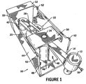
- FIG. 1 is a view of the bottom of the embodiment of the apparatus 10 , wherein the bottom of the apparatus 10 is defined as the portion of the apparatus that faces the structure to be inspected. As such, the sensor 12 is positioned proximate the bottom of the apparatus 10 to face the structure to be inspected.
- Figure 2 further illustrates an exploded view of the embodiment of the apparatus 10 depicted in Figure 1.
- the sensor 12 may be any type of sensor known to those skilled in the art and utilized to inspect structures.
- the sensor 12 is typically a non-destructive sensor, such that the sensor is capable of inspecting a structure without harming the structure or requiring disassembly of the structure.
- the sensor 12 is an eddy current sensor.
- Single and dual eddy current sensors are capable of detecting cracks and/or corrosion, particularly in metallic or other conductive structures.
- Other examples of sensors 12 are pulse-echo, thru-transmission, shear wave, resonance, pitch/catch, and mechanical impedance sensors.
- Pulse-echo, thru-transmission and shear wave sensors provide ultrasonic data, such as for thickness gauging, detection of laminar defects and porosity, and/or crack detection in the structure.
- Resonance, pitch/catch or mechanical impedance sensors provide indications of voids or porosity, such as in adhesive bondlines of the structure.
- the sensor 12 is typically in communication with a processing element to process the data accumulated by the sensor, and optionally, a display to visually present the processed data.
- communications cable(s) transmit data between the sensor 12 and the processing element and/or display.
- the data may be transmitted between the sensor 12 and the processing element and/or display via wireless communications.
- the sensor 12 may be directly connected to the processing element and/or display, or indirectly connected, such as via a network.
- the processing element and/or display may be located proximate to the sensor 12 , such that remote connections between the sensor, processing element and/or display are not necessary.
- the actuating member 14 carries the sensor 12.
- the actuating member 14 defines an aperture 16 to receive the sensor 12 .
- the aperture 16 is shown in the embodiments of the actuating member 14 illustrated in Figures 1, 2 and 3.
- the aperture 16 in the illustrated embodiments is shown near an end portion of the actuating member 14 . In other embodiments, however, the aperture for receiving the sensor 12 may be defined in any other portion of the actuating member 14 or the actuating member may carry the sensor in other manners.
- the aperture 16 may be any shape, so long as the aperture is as large or larger than the largest diameter sensor that is capable of being utilized in the apparatus 10 .
- the actuating member 14 is preferably made of a relatively resilient and non-conductive material that is also relatively flexible.
- the actuating member 14 may be made of a nylon material, such as Delrin TM , commercially available from E.I. Du Pont De Nemours and Company Corporation.
- the adjustment element 18 may be a threaded member, such as a screw, which secures the sensor within the aperture by entering the aperture through a correspondingly threaded opening that extends through the actuating member to the aperture 16 .
- the desired sensor 12 may be positioned within the aperture 16 , then the screw may be adjusted until the sensor 12 is secured between the actuating member 14 and the screw.
- the one or more adjustment element(s) may be positioned and/or shaped such that the adjustment element(s) secure the sensor within the aperture without the sensor 12 contacting the actuating member 14 .
- the actuating member 14 may be activated in any manner known to those skilled in the art to cause the actuating member to move in such a way that the sensor 12 moves in one direction relative to the surface to be inspected.
- the actuating member and thus, the sensor may move back and forth in one direction, such that the sensor 12 moves over at least a portion of the desired inspection area of a structure.
- the direction in which the actuating member moves the sensor refers to the direction defined by the reciprocating motion of the sensor and may be linear, a circular, semi-circular, or any other type of motion.
- the actuating member 14 may move along one or more rails or the like to define the desired type of movement of the actuating member 14 and sensor 12 .
- the apparatus 10 may employ any type of mechanical, electrical and/or electro-mechanical means for creating and controlling the movement of the actuating member 14 and the sensor 12 .
- the actuating member 14 may be set into motion by a motor 20 , and the movement of the actuating member 14 may be controlled by a cam system 22 .
- the motor 20 may be any type of motor known to those skilled in the art.
- the motor 20 is a gear motor, such as a gear motor commercially available from Micro Mo Electronics, Inc., which causes a shaft attached to the motor to rotate. The speed of rotation depends upon the gear ratio of the motor.
- the torque of the motor 20 should be sufficient to move the sensor 12 via the actuating member 14 over the desired surface.
- the torque of the motor should be chosen to ensure that the sensor 12 is capable of moving over the surface, even if the surface is uneven and/or rough, and even if the surface includes protruding fasteners.
- the torque of the motor may be lower, if desired.
- Power for the motor 20 may be provided in any manner known to those skilled in the art.
- power is supplied to the motor 20 via a local power supply 32 , such as batteries.
- a local power supply 32 is preferred in order to eliminate the need for a power cable between the remote power supply and the motor 20 .
- the lack of power cables and other types of cables between the apparatus 10 and other equipment is an advantage of the present invention as compared to existing automated scanning systems for scanning a surface with a sensor, which are bulky and require multiple cables between the scanning system and remote equipment.
- the embodiment of the apparatus that includes a local power supply is much more independent and portable.
- the motor 20 drives a cam system.
- One embodiment of the cam system 22 is shown in Figure 4, which includes a cam 24 and an eccentric collar 26 .
- the cam 24 is operably attached to the motor and rotates as it is driven by the motor.
- the cam 24 may be a partially semi-circular disk with an attachment piece on one side, as shown in Figure 4.
- the semi-circular shape of the cam 24 is advantageous in some embodiments of the apparatus, particularly in embodiments in which the cam 24 rotates relatively fast, to balance the weight of the cam about the point where the cam 24 attaches to the motor 20 , which prevents vibration of the actuating member 14 and the sensor 12 .
- the cam 24 may be any other suitable shape, such as circular, square, or the like.
- the cam 24 may be made of any type of metallic or non-metallic material that is sufficiently resilient to withstand the repetitive motion and pressures to which the cam is subjected during operation.
- the cam 24 is made of aluminum.
- the motor 20 is secured to the cam 24 via the attachment piece in any appropriate manner.
- the attachment piece may fit securely about or within the shaft of the motor that rotates with a fastener adapted to fasten the attachment piece to the shaft of the motor.
- the attachment piece may be secured to the shaft of the motor with an attaching compound, such as an adhesive, epoxy, cement or the like. Regardless of the manner of attachment, the attachment piece is aligned with the axis of rotation of the shaft driven by the motor.
- the collar 26 may be formed as part of the cam 24 , or it may be a separate piece that may be attached to the cam 24 .
- the collar 26 is a separate piece that may be attached to the cam 24 in any appropriate manner.
- the cam 24 may include an opening to receive and secure a portion of the collar 26 , or to receive a fastener to fasten the collar 26 to the cam 24 .
- the collar 26 may be secured to the cam 24 with an attaching compound, such as an adhesive, epoxy, cement or the like. Regardless of the manner in which the collar 26 is attached to the cam 24 , the collar 26 is eccentric with respect to the cam.
- the collar 26 is not aligned with the axis of rotation of the shaft of the motor, and therefore, not aligned with the attachment piece of the cam 24 .
- the collar 26 may be located on the side of the cam 24 that is opposite the attachment piece.
- the collar 26 may also be made of any type of appropriately resilient metallic or non-metallic material.
- the collar 26 may be made of a non-marring material.
- the collar 26 may be made of Delrin TM material, commercially available from E.I. Du Pont De Nemours and Company Corporation.
- the collar 26 cooperates with the actuating member 14 to move the actuating member in the desired manner.
- the actuating member 14 may define an elongated opening 28 , which is located a distance from the sensor. The distance between the elongated opening 28 and the sensor depends upon the range of motion of the actuating member 14 that is desired. For instance, if a broad range of motion of the actuating member 14 is desired, then the elongated opening 28 is further away from the sensor than if a smaller range of motion is desired.
- the size of the elongated opening 28 is large enough to receive the collar 26 , and to permit it to move within the elongated portion of the opening as the cam 24 rotates.
- the elongated opening is approximately 2.2 cm (seven-eighths of an inch) long.
- the cam 24 may be attached to the motor 20 , and the collar 26 may be eccentrically attached to the cam 24 .
- the actuating member 14 may then be positioned appropriately, such that the collar 26 is within the elongated opening 28 .
- at least one sensor 12 may be secured within the aperture(s) 16 , such that the sensor(s) 12 face the surface when the apparatus 10 is positioned on the surface.
- the sensor(s) 12 may contact the surface or be positioned a predetermined distance from the surface, depending upon the requirements of the sensor(s) 12 .
- the collar 26 rotates, it moves along the elongated opening 28 of the actuating member 14 , which, in turn, causes the actuating member 14 and, in turn, the sensor(s) 12 , to move in one direction.
- the collar eventually reverses its direction of movement within the elongated opening such that the actuating member and, in turn, the sensor, similarly reverse direction. As such, the sensor is moved in one direction in a reciprocating fashion.
- the actuating member 14 includes at least two substantially parallel arms 30 extending from a portion of the actuating member 14 proximate to the aperture 16 , as shown in Figure 3.
- the arms may extend from the aperture 16 to the pivot piece 34 , and be less than 50 percent of the length of the actuating member 14 .
- the parallel arms 30 are approximately 3.8 cm (one and a half inches) long.
- the arms 30 are also preferably made of a relatively resilient and non-conductive material that is also relatively flexible.
- actuating member 14 and/or the arms 30 may be made of nylon, plastic, and/or a Delrin TM material, commercially available from E.I. Du Pont De Nemours and Company Corporation.
- a pivot piece 34 may be attached to the actuating member 14 , which is shown in Figure 2.
- the pivot piece 34 is stationary, such that the actuating member 14 at least partially pivots about the pivot piece 34 .
- the pivot piece 34 may be attached to the actuating member 14 at any point to provide the desired type of control over the movement of the actuating member.
- the pivot piece is attached to the actuating member at a distance from the aperture 16 , which receives the sensor 12 .
- the distance between the pivot piece 34 and the sensor 12 may depend upon the desired range of movement of the sensor 12 . For example, the shorter the distance between the pivot piece 34 and the sensor 12 , the smaller the range of movement of the sensor 12 , and the longer the distance between the pivot piece 34 and the sensor 12 , the larger the range of movement of the sensor 12 .
- the pivot piece 34 may be attached to the actuating member 14 in any manner known to those skilled in the art.
- the pivot piece 34 may include a pivot rod 36 and a roller bearing 38 .
- the pivot rod 36 and roller bearing 38 are shaped such that the roller bearing 38 is capable of at least partially rotating on a portion of the pivot rod 36 , while simultaneously being attached to the pivot rod 36 .
- the pivot rod 36 is preferably made of a high-strength metallic and/or non-metallic material.
- the pivot rod 36 is made of steel.
- the pivot rod 36 has at least partial circumferential grooves that are capable of receiving retaining rings, such as the retaining rings commercially available from W. M. Berg, Inc., part number Q1-25.
- a roller bearing 38 may therefore be rotationally held onto pivot rod 36 by the retaining rings that prevent the roller bearing 38 from moving axially along the pivot rod 36 .
- the roller bearing 38 of this embodiment may be a roller bearing such as that commercially available from W.M. Berg, Inc., part number NRB-47.
- the roller bearing 38 may be rotationally held onto pivot rod 36 in any other manner known to those skilled in the art, such as with any other cooperating means between the roller bearing 38 and the pivot rod 36 .
- the actuating member 14 is capable of receiving the roller bearing 38 .
- the actuating member 14 may include a receptacle 40 to receive the roller bearing 38 .
- the roller bearing 38 may be attached within the receptacle 40 in any manner known to those skilled in the art, such as with friction, an adhesive compound, a fastener, or the like.
- the pivot rod 36 therefore may be capable of extending through the roller bearing 38 and the receptacle 40 to the opposite side of the actuating member 14 from the receptacle 40 , where the pivot rod 36 may be secured.
- the pivot rod 36 may not extend completely through the receptacle 40 and/or the actuating member 14 . Regardless of the degree of extension of the pivot rod 36 through the receptacle and/or the actuating member 14 , the actuating member 14 , in conjunction with the roller bearing 38 , is capable of at least partially rotating about the pivot rod 36 .
- the actuating member 14 may be balanced in order to ensure that the actuating member, and thus the sensor 12 , moves evenly over the surface.
- the weight of the sensor 12 located on one side of the pivot piece 34 may cause the actuating member 14 to wobble or experience some other type of undesirable movement when the actuating member 14 is in motion.
- a weight 42 may be applied on the side of the actuating member 14 that is opposite the sensor 12 relative to the pivot point, as shown in the embodiment of Figure 2.
- the weight 42 is shown having a cylindrical shape in Figure 2, it may be any appropriate shape that provides the amount and balance of weight that is required to counter-balance the sensor 12 with respect to the actuating member 14 .
- the weight 42 may be attached to the actuating member 14 in any manner known to those skilled in the art, such as with any type of fastener.
- the sensor(s) 12 may be removed and replaced with other sensors of varying sizes and weights, the weight 42 may similarly be removed and replaced to provide the appropriate counter weight.
- the undesirable movement of the actuating member 14 due to the weight of the sensor 12 may be prevented in any other manner known to those skilled in the art.
- the actuating member 14 may be reinforced with or made of a relatively high-strength material that prevents the undesirable movement of the actuating member due to the weight of the sensor.
- the components of the apparatus 10 are at least partially contained within a housing 44 .
- a support 46 may be attached within the housing 44 .
- the support 46 may be attached to housing 44 in any appropriate manner, such as with fasteners 48 , adhesive compound, or the like.
- the support 46 may be formed as part of the housing 44 .
- the support 46 may retain the components of the apparatus 10 in any manner such that the components are positioned relative to one another in the necessary working relationship, and such that the components are capable of being positioned as desired relative to a surface.
- Figures 1 and 2 illustrate the support 46 retaining the motor 20 and the pivot rod 36 .
- the support 46 is shaped to receive the motor 20 and the pivot rod 36 .
- the motor 20 and the pivot rod 36 may be retained in the support 46 in any manner known to those skilled in the art, such as with friction, fasteners, adhesive compound or the like.
- the cam system 22 is also retained within the housing 44 because it is attached to the motor 20 , as described hereinabove.
- the actuating member 14 is also at least partially retained within the housing 44 , such as with bracket 50 .
- the bracket 50 may also be attached to the housing 44 in any appropriate manner, such as with fasteners 48 , adhesive compound, or the like. In other embodiments of the housing 44 , the bracket 50 may be formed as part of the housing 44 .
- the bracket 50 retains the actuating member 14 in any manner known to those skilled in the art. For instance, as shown in Figures 1 and 2, the pivot rod 36 , which extends through the roller bearing 38 and the receptacle 40 is retained by the bracket 50 , which, in turn, retains the actuating member 14 . As shown, a portion of the actuating member 14 including that portion that carries the sensor may extend beyond the housing.
- the actuating member and the sensor may be disposed within the housing, if desired.
- the housing 44 is sized to be grasped by the operator, for example the housing is typically 2.2 cm (1.9 inches) wide, 7.5 cm (2.95 inches) high, and 10.2 cm (4 inches) long.
- the housing is sized such that it does not restrict the reciprocal motion of the sensor.
- the housing 44 may be positioned on the surface to be inspected by the sensor 12 , such that the sensing portion of the sensor 12 faces the surface in the desired positioned relationship, such as in contact with the surface or a spaced relation to the surface.
- the actuating member 14 may then be activated, such as by activating the motor 20 that controls the movement of the actuating member 14, and thus the movement of the sensor 12.
- the sensor 12 then moves in one direction over the surface.
- the housing 44 may then be manually moved along the surface in a desired direction.
- the housing 44 is preferably made of a non-conductive and non-marring material, such as nylon, plastic, and/or a Delrin TM material, commercially available from E.I.
- the housing 44 will not harm the surface as it moves along the surface.
- the housing 44 also may have feet 52 located along the edges of the housing 44.
- the feet 52 are also preferably made of a non-conductive and non-marring material, such as nylon, plastic, and/or a Delrin TM material, in order to protect the surface as the feet 52 slide along the surface.
- the feet 52 also facilitate movement of the housing 44 along the surface because the feet 52 may be easier to maneuver over the surface than the edges of the housing 44 , and because the feet 52 provide a passage for articles protruding from the surface, such as fasteners.
- the apparatus 10 and method for moving a sensor in at least one direction provide a faster, more exact, and easier technique for scanning a surface with a sensor than the manual method.
- the scanning technicians are not subjected to the physical fatigue that accompanies the manual method, and the object with the surface to be scanned is not retained out of service for the relatively long time that is required to perform manual scanning.
- the apparatus 10 and method for moving a sensor in at least one direction according to the present invention is less expensive, less bulky and easier to use than the conventional automated scanning techniques. Because the apparatus 10 does not require significant processing equipment or cables to remote equipment, it is easier to maneuver and easier to utilize in a field environment, in addition to being much less expensive, than complicated automated scanning systems.
Landscapes
- Chemical & Material Sciences (AREA)
- Chemical Kinetics & Catalysis (AREA)
- Electrochemistry (AREA)
- Physics & Mathematics (AREA)
- Health & Medical Sciences (AREA)
- Life Sciences & Earth Sciences (AREA)
- Analytical Chemistry (AREA)
- Biochemistry (AREA)
- General Health & Medical Sciences (AREA)
- General Physics & Mathematics (AREA)
- Immunology (AREA)
- Pathology (AREA)
- Investigating Or Analyzing Materials By The Use Of Magnetic Means (AREA)
- Transmission Devices (AREA)
- Investigating Or Analyzing Materials By The Use Of Ultrasonic Waves (AREA)
Claims (12)
- Vorrichtung (10) zum Durchführen einer Kombination von automatischer und manueller Bewegung eines nicht-destruktiven Testsensors (NDT), der in einer Öffnung (16) eines Aktorelements (14) positioniert ist, umfassend:einen NDT-Sensor (12);ein Gehäuse (44) und einen Motor (20); undwobei das Aktorelement (14) wenigstens teilweise in dem Gehäuse positioniert ist und für eine automatische Bewegung in einer Richtung angepasst ist,wobei das Aktorelement den Sensor veranlasst, Hin- und Herbewegungen auszuführen, die durch ein Nockensystem (22) oberhalb des Werkstücks kontrolliert werden, und wobei das Aktorelement wenigstens zwei im Wesentlichen parallele Arme (30) umfasst, die sich von einem Abschnitt des Aktorelements (14) nahe der Öffnung (16) erstrecken, damit der Sensor (12) das Werkstück kontaktieren kann, während der Sensor in einer im Wesentlichen normalen Relation zu einer Oberfläche des Werkstücks bleibt, wobei das Gehäuse (44) so geformt ist, dass es von einem Bediener ergriffen und manuell in eine andere Richtung bewegt werden kann, so dass der Sensor (12) durch eine Kombination von automatischer und manueller Bewegung bewegt wird.
- Vorrichtung nach Anspruch 1,
wobei das Aktorelement eine längliche Öffnung (28) definiert, die im Abstand von dem Sensor angeordnet ist; und
wobei die Vorrichtung ferner einen Nocken umfasst, der einen exzentrischen Kragen (26) besitzt, der innerhalb der länglichen Öffnung gleitet, die durch das Aktorelement definiert ist, wenn der Nocken rotiert, um den Sensor zu bewegen. - Vorrichtung nach Anspruch 2, ferner umfassend einen Motor (20), der den Nocken rotieren lässt..
- Vorrichtung nach einem der Ansprüche 1 bis 3, ferner umfassend ein Gelenkelement (34), wobei das Gelenkelement an dem Aktorelement derart befestigt ist, dass das Aktorelement wenigstens teilweise um das Gelenkelement schwenkt.
- Vorrichtung nach Anspruch 4, wobei das Gelenkelement in einem vorgegebenen Abstand von dem Sensor an dem Aktorelement befestigt ist.
- Vorrichtung nach Anspruch 4 oder 5, ferner umfassend ein Gewicht (42), welches an der dem Sensor abgewandten Seite des Aktorelements befestigt ist, um das Aktorelement auszubalancieren.
- Vorrichtung nach einem der Ansprüche 1 bis 6, wobei das Aktorelement wenigstens ein Justierelement (18) umfasst, um den Sensor an dem Aktorelement zu befestigen.
- Vorrichtung nach einem der Ansprüche 1 bis 7, wobei der Sensor ein Wirbelstromsensor ist.
- Vorrichtung nach einem der Ansprüche 1 bis 8, wobei die Arme des Aktorelements sich von dem Sensor zu dem Gelenkelement erstrecken.
- Verfahren zum Durchführen einer Kombination von automatischer und manueller Bewegung eines nicht-destruktiven Testsensors (NDT), umfassend:Positionieren eines Sensors innerhalb einer Öffnung (16) eines Aktorelements (14) benachbart zu einem zu testenden Werkstück, wobei das Aktorelement (14) wenigstens zwei im Wesentlichen parallele Arme (30) umfasst, die sich von einem Abschnitt des Aktorelements (14) aus nahe der Öffnung (16) erstrecken;automatisches Verschieben des Sensors in einer Richtung entlang dem Werkstück ohne manuelles Eingreifen bezüglich der Bewegung in der einen Richtung, wobei das Bewegen des Sensors das Kontaktieren des Werkstücks mit dem Sensor umfasst, während das Aktorelement (14) den Sensor in einer im Wesentlichen normalen Relation zu der Oberfläche des Werkstücks hält; undmanuelles Bewegen des Sensors in einer anderen Richtung, so dass der Sensor durch eine Kombination von automatisierter und manueller Bewegung bewegt wird.
- Verfahren nach Anspruch 10, wobei die automatische Bewegung des Sensors das automatische Bewegen des Sensors in einer hin- und hergehenden Bewegung bezüglich des Werkstücks umfasst.
- Verfahren nach Anspruch 10 oder 11, wobei das manuelle Bewegen des Sensors gleichzeitig mit der automatischen Bewegung des Sensors erfolgt.
Applications Claiming Priority (2)
| Application Number | Priority Date | Filing Date | Title |
|---|---|---|---|
| US10/291,959 US6829959B2 (en) | 2002-11-11 | 2002-11-11 | Apparatus and method for moving a sensor over a workpiece |
| US291959 | 2002-11-11 |
Publications (3)
| Publication Number | Publication Date |
|---|---|
| EP1418423A1 EP1418423A1 (de) | 2004-05-12 |
| EP1418423B1 true EP1418423B1 (de) | 2007-05-30 |
| EP1418423B2 EP1418423B2 (de) | 2009-11-25 |
Family
ID=32107668
Family Applications (1)
| Application Number | Title | Priority Date | Filing Date |
|---|---|---|---|
| EP03078190A Expired - Lifetime EP1418423B2 (de) | 2002-11-11 | 2003-10-09 | Gerät und Methode zur zerstörungsfreien Prüfung von Flugzeugstrukturen |
Country Status (4)
| Country | Link |
|---|---|
| US (1) | US6829959B2 (de) |
| EP (1) | EP1418423B2 (de) |
| JP (1) | JP4338499B2 (de) |
| DE (1) | DE60314079T3 (de) |
Cited By (1)
| Publication number | Priority date | Publication date | Assignee | Title |
|---|---|---|---|---|
| CN107870199A (zh) * | 2016-09-26 | 2018-04-03 | 空中客车营运有限公司 | 检查工具 |
Families Citing this family (32)
| Publication number | Priority date | Publication date | Assignee | Title |
|---|---|---|---|---|
| US20060038558A1 (en) * | 2004-08-20 | 2006-02-23 | The Boeing Company | Eddy current inspection device |
| US7640810B2 (en) * | 2005-07-11 | 2010-01-05 | The Boeing Company | Ultrasonic inspection apparatus, system, and method |
| US7444876B2 (en) * | 2005-08-26 | 2008-11-04 | The Boeing Company | Rapid prototype integrated linear ultrasonic transducer inspection apparatus, systems, and methods |
| US7464596B2 (en) * | 2004-09-24 | 2008-12-16 | The Boeing Company | Integrated ultrasonic inspection probes, systems, and methods for inspection of composite assemblies |
| US7617732B2 (en) * | 2005-08-26 | 2009-11-17 | The Boeing Company | Integrated curved linear ultrasonic transducer inspection apparatus, systems, and methods |
| US7430913B2 (en) * | 2005-08-26 | 2008-10-07 | The Boeing Company | Rapid prototype integrated matrix ultrasonic transducer array inspection apparatus, systems, and methods |
| US8402844B2 (en) * | 2008-02-27 | 2013-03-26 | Simmonds Precision Products, Inc. | Roving wireless sensor and method for use in a vehicle health and usage monitoring system |
| US8131420B2 (en) * | 2008-02-27 | 2012-03-06 | Simmonds Precision Products, Inc. | Vehicle health and usage monitoring system and method |
| DE102008042278A1 (de) * | 2008-06-13 | 2009-12-24 | Ge Inspection Technologies Gmbh | Verfahren zur zerstörungsfreien Ultraschalluntersuchung sowie Vorrichtung zur Durchführung des Verfahrens |
| US8347746B2 (en) * | 2010-01-19 | 2013-01-08 | The Boeing Company | Crawling automated scanner for non-destructive inspection of aerospace structural elements |
| US9481082B1 (en) | 2012-10-30 | 2016-11-01 | The Boeing Company | Apparatus for automated maintenance of aircraft structural elements |
| US10569907B2 (en) | 2010-01-19 | 2020-02-25 | The Boeing Company | Apparatus for automated maintenance of aircraft structural elements |
| US9643313B2 (en) | 2010-01-19 | 2017-05-09 | The Boeing Company | Apparatus for automated maintenance of aircraft structural elements |
| US9302787B2 (en) | 2012-09-14 | 2016-04-05 | The Boeing Company | Vacuum adhering apparatus for automated maintenance of airfoil-shaped bodies |
| US9003880B2 (en) * | 2012-12-31 | 2015-04-14 | General Electric Company | Reference speed measurement for a non-destructive testing system |
| US9334066B2 (en) * | 2013-04-12 | 2016-05-10 | The Boeing Company | Apparatus for automated rastering of an end effector over an airfoil-shaped body |
| US9746445B2 (en) | 2013-04-16 | 2017-08-29 | The Boeing Company | Apparatus for automated non-destructive inspection of airfoil-shaped bodies |
| JP6261939B2 (ja) * | 2013-10-23 | 2018-01-17 | 三菱重工業株式会社 | 可搬式の超音波探傷装置及び超音波探傷方法 |
| US10197392B2 (en) * | 2015-06-23 | 2019-02-05 | The Boeing Company | Automated resin ridge reduction system |
| ES2949436T3 (es) * | 2015-12-15 | 2023-09-28 | Speno International | Vehículo ferroviario y procedimiento de localización de defectos o de irregularidades en la superficie de raíles de ferrocarril |
| US9950813B2 (en) | 2016-02-05 | 2018-04-24 | The Boeing Company | Non-destructive inspection of airfoil-shaped body using self-propelling articulated robot |
| US10717162B2 (en) | 2017-12-07 | 2020-07-21 | The Boeing Company | Automated apparatus for moving an end effector over a surface of an airfoil-shaped body |
| US10634123B2 (en) | 2017-12-14 | 2020-04-28 | The Boeing Company | Apparatus and methods for maintenance of wind turbine blades |
| US10953938B2 (en) | 2018-03-15 | 2021-03-23 | The Boeing Company | Apparatus and methods for maintenance of wind turbine blades |
| US10823709B2 (en) | 2018-07-06 | 2020-11-03 | The Boeing Company | Methods and apparatus for realigning and re-adhering a hanging crawler vehicle on a non-level surface |
| US11053925B2 (en) | 2018-07-19 | 2021-07-06 | The Boeing Company | Cable-suspended non-destructive inspection units for rapid large-area scanning |
| US11007635B2 (en) | 2018-07-25 | 2021-05-18 | The Boeing Company | Gravity compensation for self-propelled robotic vehicles crawling on non-level surfaces |
| US11149718B2 (en) | 2018-08-21 | 2021-10-19 | The Boeing Company | Methods and apparatus for maintaining airfoil-shaped body using cart that follows trailing edge |
| US10955310B2 (en) | 2018-09-12 | 2021-03-23 | The Boeing Company | Vacuum-adhering apparatus for automated inspection of airfoil-shaped bodies with improved surface mounting |
| KR102236995B1 (ko) * | 2020-11-12 | 2021-04-06 | 주식회사 미래기술 | 와류검사장치 |
| CA3235988A1 (en) * | 2021-10-21 | 2023-04-27 | Evident Canada, Inc. | Free hand acoustic probe tracking |
| WO2026088313A1 (ja) * | 2024-10-23 | 2026-04-30 | Smc株式会社 | センサユニット |
Family Cites Families (10)
| Publication number | Priority date | Publication date | Assignee | Title |
|---|---|---|---|---|
| US3628375A (en) * | 1970-04-28 | 1971-12-21 | Dominick A Pagano | Apparatus for ultrasonic inspection of a length of test material |
| US4134067A (en) † | 1977-09-09 | 1979-01-09 | The Boeing Company | Rotary eddy current flaw detector utilizing differentially unbalanced coils and the amplitude of a rotary induced pulse to produce the charging voltage for the sweep generator |
| AT358712B (de) * | 1979-01-11 | 1980-09-25 | Kretztechnik Gmbh | Verfahren zur untersuchung von objekten nach dem ultraschall-schnittbildverfahren und schnittbildgeraet zur durchfuehrung dieses verfahrens |
| US4774842A (en) * | 1986-02-19 | 1988-10-04 | Mcdonnell Douglas Corporation | Hand-held apparatus to nondestructively test subsurface structure |
| JPH0875706A (ja) † | 1994-09-06 | 1996-03-22 | Mitsubishi Heavy Ind Ltd | 機体検査装置 |
| US5698787A (en) | 1995-04-12 | 1997-12-16 | Mcdonnell Douglas Corporation | Portable laser/ultrasonic method for nondestructive inspection of complex structures |
| US5567881A (en) * | 1995-05-05 | 1996-10-22 | Mcdonnell Douglas Corporation | Method and apparatus for inspecting a structural part having surface irregularities |
| FR2772121B1 (fr) | 1997-12-10 | 2000-06-09 | Metalscan | Dispositif permettant de determiner la position d'un ensemble mobile de sondes de mesure |
| US6220099B1 (en) | 1998-02-17 | 2001-04-24 | Ce Nuclear Power Llc | Apparatus and method for performing non-destructive inspections of large area aircraft structures |
| US6339331B1 (en) | 1999-12-14 | 2002-01-15 | General Electric Company | Methods and apparatus for inspecting TV-shaped openings, using eddy current |
-
2002
- 2002-11-11 US US10/291,959 patent/US6829959B2/en not_active Expired - Lifetime
-
2003
- 2003-10-09 DE DE60314079T patent/DE60314079T3/de not_active Expired - Lifetime
- 2003-10-09 EP EP03078190A patent/EP1418423B2/de not_active Expired - Lifetime
- 2003-11-06 JP JP2003377117A patent/JP4338499B2/ja not_active Expired - Lifetime
Cited By (2)
| Publication number | Priority date | Publication date | Assignee | Title |
|---|---|---|---|---|
| CN107870199A (zh) * | 2016-09-26 | 2018-04-03 | 空中客车营运有限公司 | 检查工具 |
| CN107870199B (zh) * | 2016-09-26 | 2020-08-28 | 空中客车营运有限公司 | 检查工具 |
Also Published As
| Publication number | Publication date |
|---|---|
| DE60314079D1 (de) | 2007-07-12 |
| DE60314079T2 (de) | 2008-01-24 |
| DE60314079T3 (de) | 2010-05-20 |
| US20040089082A1 (en) | 2004-05-13 |
| JP4338499B2 (ja) | 2009-10-07 |
| EP1418423A1 (de) | 2004-05-12 |
| EP1418423B2 (de) | 2009-11-25 |
| JP2004163428A (ja) | 2004-06-10 |
| US6829959B2 (en) | 2004-12-14 |
Similar Documents
| Publication | Publication Date | Title |
|---|---|---|
| EP1418423B2 (de) | Gerät und Methode zur zerstörungsfreien Prüfung von Flugzeugstrukturen | |
| US7484413B2 (en) | Remote radius inspection tool for composite joints | |
| EP1709438B1 (de) | Zerstörungsfreie inspektionsvorrichtung zur inspektion schwer zugänglicher elemente einer struktur | |
| US7231826B2 (en) | Non-destructive inspection device for inspecting limited-access features of a structure | |
| CA2726972C (en) | Crawling automated scanner for non-destructive inspection of aerospace structural elements | |
| JP5495562B2 (ja) | 検査システムおよび関連される方法 | |
| US7508971B2 (en) | Inspection system using coordinate measurement machine and associated method | |
| US4304133A (en) | Positioning device for scanner | |
| US8185327B2 (en) | Monitoring of composite materials | |
| EP1744157B1 (de) | System und Verfahren für Ultraschallprüfung | |
| US20060201252A1 (en) | Angle beam shear wave through-transmission ultrasonic testing apparatus and method | |
| US10788455B2 (en) | Extended reach inspection apparatus | |
| US7328630B2 (en) | End effector inspection apparatus and method | |
| US7562593B2 (en) | Apparatus and methods for adjustably supporting probes | |
| CN114813928A (zh) | 基于阵列涡流的发电机护环检测装置及检测方法 | |
| Barnard et al. | Towards a generic manual scanner for nondestructive inspection | |
| US20070089549A1 (en) | Apparatus and methods for adjustably supporting probes | |
| CN120685790A (zh) | 一种金属零件电磁声发射无损检测装置 | |
| GB2580018A (en) | Non-destructive testing tool for dual axis position encoding of an inspection probe |
Legal Events
| Date | Code | Title | Description |
|---|---|---|---|
| PUAI | Public reference made under article 153(3) epc to a published international application that has entered the european phase |
Free format text: ORIGINAL CODE: 0009012 |
|
| AK | Designated contracting states |
Kind code of ref document: A1 Designated state(s): AT BE BG CH CY CZ DE DK EE ES FI FR GB GR HU IE IT LI LU MC NL PT RO SE SI SK TR |
|
| AX | Request for extension of the european patent |
Extension state: AL LT LV MK |
|
| 17P | Request for examination filed |
Effective date: 20040527 |
|
| AKX | Designation fees paid |
Designated state(s): DE GB |
|
| 17Q | First examination report despatched |
Effective date: 20050613 |
|
| GRAP | Despatch of communication of intention to grant a patent |
Free format text: ORIGINAL CODE: EPIDOSNIGR1 |
|
| GRAS | Grant fee paid |
Free format text: ORIGINAL CODE: EPIDOSNIGR3 |
|
| GRAA | (expected) grant |
Free format text: ORIGINAL CODE: 0009210 |
|
| AK | Designated contracting states |
Kind code of ref document: B1 Designated state(s): DE GB |
|
| REG | Reference to a national code |
Ref country code: GB Ref legal event code: FG4D |
|
| REF | Corresponds to: |
Ref document number: 60314079 Country of ref document: DE Date of ref document: 20070712 Kind code of ref document: P |
|
| PLBI | Opposition filed |
Free format text: ORIGINAL CODE: 0009260 |
|
| PLAX | Notice of opposition and request to file observation + time limit sent |
Free format text: ORIGINAL CODE: EPIDOSNOBS2 |
|
| 26 | Opposition filed |
Opponent name: AIRBUS SAS Effective date: 20080227 |
|
| PLAF | Information modified related to communication of a notice of opposition and request to file observations + time limit |
Free format text: ORIGINAL CODE: EPIDOSCOBS2 |
|
| RAP2 | Party data changed (patent owner data changed or rights of a patent transferred) |
Owner name: THE BOEING COMPANY |
|
| PLBB | Reply of patent proprietor to notice(s) of opposition received |
Free format text: ORIGINAL CODE: EPIDOSNOBS3 |
|
| PUAH | Patent maintained in amended form |
Free format text: ORIGINAL CODE: 0009272 |
|
| STAA | Information on the status of an ep patent application or granted ep patent |
Free format text: STATUS: PATENT MAINTAINED AS AMENDED |
|
| 27A | Patent maintained in amended form |
Effective date: 20091125 |
|
| AK | Designated contracting states |
Kind code of ref document: B2 Designated state(s): DE GB |
|
| PGFP | Annual fee paid to national office [announced via postgrant information from national office to epo] |
Ref country code: GB Payment date: 20221027 Year of fee payment: 20 Ref country code: DE Payment date: 20221027 Year of fee payment: 20 |
|
| P01 | Opt-out of the competence of the unified patent court (upc) registered |
Effective date: 20230503 |
|
| REG | Reference to a national code |
Ref country code: DE Ref legal event code: R071 Ref document number: 60314079 Country of ref document: DE |
|
| REG | Reference to a national code |
Ref country code: GB Ref legal event code: PE20 Expiry date: 20231008 |
|
| PG25 | Lapsed in a contracting state [announced via postgrant information from national office to epo] |
Ref country code: GB Free format text: LAPSE BECAUSE OF EXPIRATION OF PROTECTION Effective date: 20231008 |
|
| PG25 | Lapsed in a contracting state [announced via postgrant information from national office to epo] |
Ref country code: GB Free format text: LAPSE BECAUSE OF EXPIRATION OF PROTECTION Effective date: 20231008 |