EP1418478B1 - Gerät zum Lesen eines Identifkationsverbinders - Google Patents
Gerät zum Lesen eines Identifkationsverbinders Download PDFInfo
- Publication number
- EP1418478B1 EP1418478B1 EP03292576A EP03292576A EP1418478B1 EP 1418478 B1 EP1418478 B1 EP 1418478B1 EP 03292576 A EP03292576 A EP 03292576A EP 03292576 A EP03292576 A EP 03292576A EP 1418478 B1 EP1418478 B1 EP 1418478B1
- Authority
- EP
- European Patent Office
- Prior art keywords
- connector
- appliance
- identification
- appliance according
- information
- Prior art date
- Legal status (The legal status is an assumption and is not a legal conclusion. Google has not performed a legal analysis and makes no representation as to the accuracy of the status listed.)
- Expired - Lifetime
Links
Images


Classifications
-
- G—PHYSICS
- G05—CONTROLLING; REGULATING
- G05B—CONTROL OR REGULATING SYSTEMS IN GENERAL; FUNCTIONAL ELEMENTS OF SUCH SYSTEMS; MONITORING OR TESTING ARRANGEMENTS FOR SUCH SYSTEMS OR ELEMENTS
- G05B19/00—Program-control systems
- G05B19/02—Program-control systems electric
- G05B19/04—Program control other than numerical control, i.e. in sequence controllers or logic controllers
- G05B19/12—Program control other than numerical control, i.e. in sequence controllers or logic controllers using record carriers
- G05B19/128—Program control other than numerical control, i.e. in sequence controllers or logic controllers using record carriers the workpiece itself serves as a record carrier, e.g. by its form, by marks or codes on it
-
- G—PHYSICS
- G05—CONTROLLING; REGULATING
- G05B—CONTROL OR REGULATING SYSTEMS IN GENERAL; FUNCTIONAL ELEMENTS OF SUCH SYSTEMS; MONITORING OR TESTING ARRANGEMENTS FOR SUCH SYSTEMS OR ELEMENTS
- G05B2219/00—Program-control systems
- G05B2219/30—Nc systems
- G05B2219/49—Nc machine tool, till multiple
- G05B2219/49302—Part, workpiece, code, tool identification
Definitions
- the present invention relates to the field of identification connectors used in particular in aircraft engines in the parameterization of the engine computer.
- the invention relates more particularly to an apparatus for reading the contents of such connectors before assembling the engine to the aircraft.
- the invention can be used to check the programming of the fields that can be modified by an operator.
- the computer must be parameterized according to the family and the version of the engine considered.
- an identification connector is used which is integral with the motor and which is connected to the computer. This identification connector contains the information (in binary coded form) relating to the characteristics of the engine that will be used by the computer.
- FIG 8 illustrates an example of an identification connector considered in the present invention.
- the identification connector 100 comprises a plurality of pins 101 which are interconnected within the connector by an electric circuit (not shown) reprogrammable or not.
- a non-reprogrammable electrical circuit In the case of a non-reprogrammable electrical circuit, it is formed of discrete components, such as fuse tracks, which connect the pins of the connector. In a known manner, the codification of the information in the connector is effected by melting certain fuse tracks. Thus, at each pin of the connector corresponds a binary data (0 or 1). Once the connector installed on the motor (i.e. connected to the computer), the computer interprets, in binary, the electrical diagram defined in the connector to acquire the characteristics of the engine.
- the binary data can be determined by a switch for example.
- the reliability of the information contained in the identification connector is of paramount importance especially since the connectors have identical keying keys to be installed on all computers. Indeed, it is the identification connector that will allow or prohibit certain operating characteristics specific to each family and engine version. For example, a version or engine family defined for a maximum thrust of 20,000 pounds may be equipped with a connector allowing thrust up to 22,000 pounds or thrust limiting to 18,000 pounds. Knowing that some engine components are not suitable for thrust beyond 20,000 pounds, or that with a thrust of 18,000 pounds can prevent the takeoff, such an error can have serious consequences.
- the reading operation of the identification connector makes it possible to ensure, before mounting the engine under the wing of the aircraft, the characteristics of the engine. Thus, it is possible to check the choices made from the engine booklets and to avoid mounting inadvertent in terms of downtimes and costs.
- the first option is to manually read the raw data (i.e., binary) present in the connector. This operation is performed by an operator who uses an ohmmeter to read the value measured on each connector contact. Once all the data has been collected, the operator decodes this information using the manufacturer documents to check the correspondence between the information coded in the identification connector and the characteristics of the engine to which it must be associated.
- This first solution is a tedious manual operation that involves risks of error and deterioration during measurements by the operator, particularly because of the proximity of the contacts in the connector.
- the second possibility currently known to validate the data contained in an identification connector is to mount the engine, with the computer equipped with the identification connector, under the wing of the aircraft to read the information coded in the connector by via the on-board computer.
- This solution is even more tedious than the first described above.
- the assembly and disassembly of the engine on the aircraft entail costs in terms of time and manpower that are not eligible in this type of industry.
- EP-A-0 366 854 discloses an apparatus for analyzing blood samples contained in pouches.
- a connector is attached to each pocket and encloses a PROM memory circuit in which information relating to the sample is recorded. This information can be read by the analyzer by connecting the pocket connector to a connector on the device.
- the present invention aims to remedy the aforementioned drawbacks and to provide a device that allows to read more reliably, faster and without risk of degradation the information contained in a identification connector and this without disassembling other parts of the engine.
- an engine identification connector reading apparatus comprising a plurality of contacts connected to a decoder circuit, each contact corresponding to a bit data and one or more of said bit data corresponding to characteristics information.
- the reading apparatus comprising connecting means adapted to receive at least one identification connector, control members, a display device and processing means, characterized in that the connecting means are connected the processing means responsive to the controllers for displaying the information contained in the connector on the display device, and in that the processing means of the reading apparatus are programmed to address one or more contacts of the connector of the identification connected to the device to obtain the binary data of the discrete element connected at each interrogated contact, the processing means comprising software means for decoding the information relating to the characteristics of the engine from the binary data read on the contact or contacts of the identification connector.
- the present invention provides an apparatus which makes it possible to read in clear the information contained in an identification connector. An operator can therefore check in all places and at all times the compatibility of the connector information referring to the characteristics of the motor to which it is to be connected.
- control members comprise one or more buttons for controlling the display of the coded information in the identification connector connected to the reading device, each information being successively displayed in response to a pressure. on the button.
- control members may be software means for displaying the information one after the other, or all together on a suitable display device.
- the identification connector may be a multi-pin connector.
- the connection means of the reading device comprise at least one multi-pin connector adapted to receive the identification connector.
- connection means comprise at least one connector for each receiving at least one specific identification connector model.
- the processing means comprise software means for detecting the model of the identification connector connected to the apparatus.
- the processing means may also comprise software means for performing a parity test of the coding circuit of the identification connector.
- the reading apparatus comprises at least one protection connector comprising a self-test circuit.
- the processing means comprise software means for performing a test of the reading device from the self-test circuit of the protection connector.
- the control members may comprise at least one button for controlling the display of the test result of the reading device or the automatic display means of the result as described above.
- the reading apparatus may be equipped with connection means for updating the software described above.
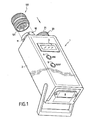
- FIG. 1 represents a reading device 1 of identification connectors according to the invention presented on the side of its upper face.
- the reading device 1 is formed of a housing 2 which comprises two buttons 4 and 5 and a display 3 such as an LCD screen for example.
- the buttons 4 and 5 serve as control means for the operator to display information on the display 3.
- the housing 2 comprises also two connectors 10 and 20 for receiving and adapting with identification connectors 100.
- the reading device according to the invention being portable, the housing 2 further comprises autonomous power supply means, such as for example four 1.5-volt batteries, which are housed in a drawer 6 inside the housing 2.
- the drawer 6 may constitute a housing for a rechargeable battery.
- the drawer 6 may include means for connecting a charger to the battery.
- Figure 2 shows the part of the reading apparatus that receives the identification connector or connectors to be tested.
- the housing 2 comprises on its front face two connectors 10 and 20 (male or female depending on the case) integral with the latter.
- the identification connector 100 is in the form of a male connector which comprises a plurality of pins 101 disposed inside a body 105.
- the connector 100 may also be a female connector.
- the body 105 of the connector encloses the electrical data coding circuit which is connected to the non-visible ends of the pins 101.
- the portion of the body 105 which surrounds the pins 101 is formed of a ring 103 which is free to rotate.
- the ring 103 comprises bayonets 104 intended to cooperate with grooves 11 of the corresponding connector 10.
- the fastening means may be of various shapes, for example a thread.
- the connector 20 of the apparatus shown in FIG. 2 the connector will comprise a corresponding thread 21 for screwing on the identification connector.
- the connectors 10 and 20 each respectively comprise a plurality of contact cavities 12 and 22 for receiving the pins of the connector and thereby establishing an electrical connection between the reading apparatus 1 and the coding circuit of the identification connector.
- the connectors 10 and 20 are respectively provided with protection connectors 30 and 40 as shown in FIG. 4.
- Each protective connector 30, respectively 40 is permanently attached to the connector. housing 2 by a fastening system 31, respectively 41, such as a cable or the like.
- the connectors 30 and 40 contain a decoding circuit which contains information for performing a self-test of the reading device as explained in more detail below.
- the decoding circuit may for example consist of a blank circuit where all the discrete elements are at 1. This feature of the protection connectors allows the operator to control the correct operation of the reading device before an operation. reading identification connectors to check.
- FIG. 5 shows the main components that are implemented in the electronic circuit of the reading apparatus of the present invention.
- the circuit 15 comprises a microcontroller 8 which implements programs stored in an associated memory unit 9.
- the memory unit 9 contains mainly a reading program (TEST MODE) for connectors equipped with a self-test circuit and three reading programs (MODE V.1, V.2 and V. 3) identification connectors each corresponding to a specific connector model.
- the apparatus according to the invention may advantageously comprise connecting means (not shown), such as an RS232 serial port, connected to the microcontroller for updating the programs in the apparatus.
- connecting means such as an RS232 serial port
- the microcontroller 8 reads the data contained in the identification connectors via a bus 13 and an input / output interface 7 which may be formed of a diode matrix for example. More precisely, with each press of an operator on one of the keys 4 or 5 the microcontroller 8 will read and decode the bit data of the identification connector corresponding to the information requested by the program. Once the data has been decoded, the microcontroller displays on the display 3 the corresponding information.
- control members may be software means for displaying information one after the other or all together on a display device of suitable size.
- the information is displayed successively after each press of an operator on one of the buttons 4 or 5.
- the The operator uses only the "USE" key 4.
- the program detects whether the connector in place is a protection connector with a self-test circuit as for the connectors 30 and 40 presented in FIG. 4. If this is the case, the result of the self-test is displayed. on the display 3 in a step ST2.
- the self-test operation of the apparatus will be described in detail later.
- the device To detect the presence of connectors, the device reads the binary values on the contacts of the connectors 10 and 20. If all the values are at 0 then there is no connector connected.
- step ST3 consists of detecting the model of the identification connector present in order to execute the program. appropriate reading of information.
- the information relating to the version of the connector is obtained by interrogation of one or more discrete elements of the circuit connected to the pins of the connector which form a code which will be interpreted by the program to decode and view the version of the engine concerned. More precisely, each pin of the connector is identified by a unique reference (eg a letter). Thus, by addressing one or more pins, the microcontroller can obtain the binary data or data that it must interpret to obtain the information.
- FIG. 3 shows an example of an identification connector for motors comprising 26 pins each referenced by a letter going from A to Z.
- the connector 20 of FIG. 2 is able to receive the identification connectors. for two different motor models while the connector 10 receives only identification connectors for the same engine model.
- the value of the discrete element connected to the pin W will determine the model of the motor that corresponds to the connector in place.
- the model (V.1, V.2 or V.3) of the identification connector is recognized by the microcontroller which will then load, from the memory unit 9, the software for reading the corresponding information (step ST4).
- the software first initiates a parity check step ST5 which consists in adding all or some binary values contained in the connector. If a problem of parity is detected, the microcontroller will then display a message "PARITE?" (Step ST6) on the display 3 to inform the operator. The operation of reading and checking the information contained in the identification connector by the operator can then begin in a step ST7 where the number of increments made by the operator on the button "USE" 4 is stored. Indeed, each time the "USE" button is pressed, the operator will successively display all the information contained in the connector in an order defined by the software. In the example of FIG. 6, the software loaded in the microcontroller will successively display the information as a function of the value n of increments of the button.
- step ST8 if the duration between two presses on the button is greater than a determined duration, the latter returns to the initial step ST0 which corresponds to the standby state of the apparatus.
- the microcontroller 8 also contains in its memory unit 9 a program which, in association with protection connectors equipped with a self-test circuit (eg blank circuit with discrete elements at 1), makes it possible to perform a self-test of the reading device 1.
- a self-test circuit eg blank circuit with discrete elements at 1
- This self-test operation of the device is useful in all cases where there may be a doubt about its operation (eg systematic parity problem).
- the self test is also useful for controlling the device after a change (eg microcontroller replacement or batteries).
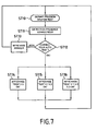
- Figure 7 illustrates the steps of the self-test operation of the apparatus.
- the "TEST MODE” program is executed from the memory unit 9 in the microcontroller (step ST10).
- This self-test program is also executed in the microcontroller when a protection connector with a self-test circuit is detected in step ST1 of FIG. 5.
- a step ST11 the program detects the location of the connector on the device.
- the connector 20 of FIG. 2 is able to receive the identification connectors V.1 and V.2 versions while the connector 10 only receives version V.3 identification connectors.
- a step ST12 for checking the presence of a self-test connector is initiated. If the present connector is not detected as a test connector (ie if all or some discrete elements are not at 1), an error message is displayed on the apparatus (step ST13). If the connector in place on the device is detected as a self-test connector (ie all the discrete elements to be considered are at 1), a message of test result is displayed.
- the device will display the corresponding message.
- the message "TEST V.3 OK” will be displayed (step ST4).
- the message "TEST V.1 V.2 OK” will be displayed (step ST5).
- the message "TEST V.1 V.2 V.3” will be displayed (step ST6).
- the reading apparatus constitutes a more reliable and practical tool than the manual control methods which makes it possible to read in any place and at any time the information contained in an identification connector to ensure their compatibility with the characteristics of the motor on which the connector is or must be installed.
- the information (name of the parameter and its attribute) is directly displayed in clear, which facilitates the verification task for the operator.
Landscapes
- Physics & Mathematics (AREA)
- General Physics & Mathematics (AREA)
- Engineering & Computer Science (AREA)
- Automation & Control Theory (AREA)
- Details Of Connecting Devices For Male And Female Coupling (AREA)
- Coupling Device And Connection With Printed Circuit (AREA)
- Mechanical Coupling Of Light Guides (AREA)
- Arrangements For Transmission Of Measured Signals (AREA)
- Manufacturing Of Electrical Connectors (AREA)
- Test And Diagnosis Of Digital Computers (AREA)
Claims (13)
- Gerät (1) zum Lesen von Identifikationssteckern (100), ausgelegt für einen Flugzeugmotor, wobei der Stecker eine Vielzahl von Kontakten (101) umfaßt, die mit einer Decodierungsschaltung verbunden sind, wobei jeder Kontakt einem binären Datum entspricht, wobei eines oder mehrere der binären Daten Informationen über die Merkmale des Motors entsprechen, wobei das Gerät zur Aufnahme wenigstens eines Identifikationsstecker ausgelegte Anschlußmittel (10, 20), Steuerelemente (4, 5), eine Anzeigevorrichtung (3) und Bearbeitungsmittel umfaßt,
dadurch gekennzeichnet, daß die Anschlußmittel mit den Bearbeitungsmitteln (8) verbunden sind, die auf die Steuerelemente reagieren, um die in dem Stecker enthaltenen Informationen auf der Anzeigevorrichtung (3) anzuzeigen, und daß die Bearbeitungsmittel (8) des Geräts (1) zum Lesen derart programmiert sind, daß sie einen oder mehrere Kontakte des an das Gerät angeschlossenen Identifikationssteckers adressieren, um das Binärdatum des diskreten Elements zu erhalten, das mit jedem abgefragten Kontakt verbunden ist, wobei die Bearbeitungsmittel Softwaremittel umfassen, um die Informationen über die Merkmale des Motors aus den an dem oder den Kontakten des Identifikationssteckers (100) ausgelesenen Binärdaten zu decodieren. - Gerät nach Anspruch 1, dadurch gekennzeichnet, daß die Steuerelemente mindestens einen Knopf (4) umfassen, um die Anzeige der in dem an das Gerät (1) zum Lesen angeschlossenen Identifikationsstecker (100) codierten Informationen zu steuern, wobei jede Information nacheinander als Antwort auf ein Drücken auf den Knopf angezeigt wird.
- Gerät nach Anspruch 1, dadurch gekennzeichnet, daß die Steuerelemente Softwaremittel umfassen, die die automatische Anzeige der Informationen ermöglichen.
- Gerät nach einem der Ansprüche 1 bis 3, dadurch gekennzeichnet, daß der Identifikationsstecker (100) ein Mehrfachstecker ist, und daß die Anschlußmittel des Geräts mindestens einen Mehrfachstecker (10) umfassen, der den Identifikationsstecker aufnehmen kann.
- Gerät nach einem der Ansprüche 1 bis 4, dadurch gekennzeichnet, daß die Anschlußmittel mindestens einen Stecker (10) umfassen, um mindestens ein spezifisches Modell eines Identifikationssteckers aufzunehmen.
- Gerät nach einem der Ansprüche 1 bis 5, dadurch gekennzeichnet, daß die Bearbeitungsmittel (8) Softwaremittel (9) umfassen, um das Modell des an das Gerät angeschlossenen Identifikationssteckers zu erfassen.
- Gerät nach einem der Ansprüche 1 bis 6, dadurch gekennzeichnet, daß die Bearbeitungsmittel (8) Softwaremittel (9) umfassen, um einen Paritätstest der Codierschaltung des Identifikationssteckers durchzuführen.
- Gerät nach einem der Ansprüche 1 bis 7, dadurch gekennzeichnet, daß es mindestens einen Schutzstecker (30) umfaßt, der eine Autotestschaltung besitzt.
- Gerät nach Anspruch 8, dadurch gekennzeichnet, daß die Bearbeitungsmittel (8) Softwaremittel umfassen, um einen Test des Geräts zum Lesen auf Basis der Autotestschaltung des Schutzsteckers (30) durchzuführen.
- Gerät nach Anspruch 9, dadurch gekennzeichnet, daß die Steuerelemente mindestens einen Knopf (5) umfassen, um die Anzeige des Resultats des Tests des Geräts zum Lesen zu steuern.
- Gerät nach Anspruch 9, dadurch gekennzeichnet, daß die Steuerelemente Softwaremittel umfassen, um automatisch die Anzeige des Resultats des Tests des Geräts zum Lesen zu steuern.
- Gerät nach einem der Ansprüche 1 bis 11, dadurch gekennzeichnet, daß es Mittel zur Aktualisierung der Bearbeitungsmittel umfaßt.
- Gerät nach einem der Ansprüche 1 bis 12, dadurch gekennzeichnet, daß es autonome Versorgungsmittel (6) umfaßt.
Applications Claiming Priority (2)
| Application Number | Priority Date | Filing Date | Title |
|---|---|---|---|
| FR0213094A FR2846110B1 (fr) | 2002-10-21 | 2002-10-21 | Appareil de lecture de connecteurs d'identification |
| FR0213094 | 2002-10-21 |
Publications (2)
| Publication Number | Publication Date |
|---|---|
| EP1418478A1 EP1418478A1 (de) | 2004-05-12 |
| EP1418478B1 true EP1418478B1 (de) | 2007-04-11 |
Family
ID=32050590
Family Applications (1)
| Application Number | Title | Priority Date | Filing Date |
|---|---|---|---|
| EP03292576A Expired - Lifetime EP1418478B1 (de) | 2002-10-21 | 2003-10-16 | Gerät zum Lesen eines Identifkationsverbinders |
Country Status (9)
| Country | Link |
|---|---|
| US (1) | US7078886B2 (de) |
| EP (1) | EP1418478B1 (de) |
| JP (1) | JP4074576B2 (de) |
| AT (1) | ATE359543T1 (de) |
| CA (1) | CA2444984C (de) |
| DE (1) | DE60313104T2 (de) |
| ES (1) | ES2285063T3 (de) |
| FR (1) | FR2846110B1 (de) |
| PT (1) | PT1418478E (de) |
Families Citing this family (5)
| Publication number | Priority date | Publication date | Assignee | Title |
|---|---|---|---|---|
| DE102005048248B4 (de) * | 2005-10-07 | 2015-12-03 | Amphenol-Tuchel Electronics Gmbh | Abschlussstecker für Antennenanlagen und Steckverbindung mit einem solchen Abschlussstecker |
| FR2951562B1 (fr) * | 2009-10-15 | 2012-06-29 | Airbus Operations Sas | Procede securise pour acceder a un systeme d'information d'un aeronef |
| DE102010028263A1 (de) * | 2010-04-27 | 2011-10-27 | Airbus Operations Gmbh | Verfahren und Vorrichtung zum Identifizieren einer Zuordnung von Regelkreisen zu mindestens einer Regelvorrichtung |
| DE102022129504A1 (de) * | 2022-11-08 | 2024-05-08 | Rolls-Royce Deutschland Ltd & Co Kg | Elektrische Antriebseinheit für ein Luftfahrzeug |
| CN118610834A (zh) * | 2024-05-27 | 2024-09-06 | 济南腊山航空科技有限公司 | 一种特情记录器处理系统 |
Family Cites Families (13)
| Publication number | Priority date | Publication date | Assignee | Title |
|---|---|---|---|---|
| US4280185A (en) * | 1979-08-06 | 1981-07-21 | United Technologies Corporation | Engine module life tracking system |
| US4787053A (en) * | 1981-12-30 | 1988-11-22 | Semco Instruments, Inc. | Comprehensive engine monitor and recorder |
| DE3229065C2 (de) * | 1982-08-04 | 1984-09-27 | Daimler-Benz Ag, 7000 Stuttgart | Drehzahlmesser mit Ökonomiefeld |
| US4571488A (en) * | 1985-01-29 | 1986-02-18 | E. I. Du Pont De Nemours And Company | Heat-fusion pipe fitting system |
| DE3505155A1 (de) * | 1985-02-15 | 1986-08-21 | Elastogran Maschinenbau GmbH, 2844 Lemförde | Vorrichtung zur herstellung von formteilen aus mehrkomponentenkunststoff, insbesondere polyurethan, mit einer programmsteuerung |
| US4975647A (en) * | 1987-06-01 | 1990-12-04 | Nova Biomedical Corporation | Controlling machine operation with respect to consumable accessory units |
| SE8802566L (sv) * | 1988-07-08 | 1990-01-09 | Atlas Copco Tools Ab | Motordrivet verktyg och drivsystem foer detta |
| US5146172A (en) * | 1990-08-15 | 1992-09-08 | Sundstrand Corp. | Engine identification system |
| DE19731283B4 (de) * | 1997-07-21 | 2018-07-26 | Bayerische Motoren Werke Aktiengesellschaft | Diagnoseprüfgerät für elektronische Steuergeräte in unterschiedlichen Kraftfahrzeugtypen |
| US6044700A (en) * | 1997-10-14 | 2000-04-04 | Endevco Corporation | Aircraft equipment configuration identification interface guide |
| ES2188444T3 (es) * | 2000-05-05 | 2003-07-01 | Edomat Deutschland Treuhand Un | Procedimiento para la gestion y control administrativo de aparatos de la industria aeronautica que deber ser sometidos a comprobaciones. |
| US6570385B1 (en) * | 2001-03-19 | 2003-05-27 | Actron Manufacturing Co. | Handheld tester for starting/charging systems |
| DE50107679D1 (de) * | 2001-03-23 | 2005-11-17 | Grundfos As | Elektromotor mit elektronischer Steuerung |
-
2002
- 2002-10-21 FR FR0213094A patent/FR2846110B1/fr not_active Expired - Fee Related
-
2003
- 2003-10-16 ES ES03292576T patent/ES2285063T3/es not_active Expired - Lifetime
- 2003-10-16 PT PT03292576T patent/PT1418478E/pt unknown
- 2003-10-16 DE DE60313104T patent/DE60313104T2/de not_active Expired - Lifetime
- 2003-10-16 AT AT03292576T patent/ATE359543T1/de not_active IP Right Cessation
- 2003-10-16 EP EP03292576A patent/EP1418478B1/de not_active Expired - Lifetime
- 2003-10-17 JP JP2003357857A patent/JP4074576B2/ja not_active Expired - Lifetime
- 2003-10-20 CA CA2444984A patent/CA2444984C/fr not_active Expired - Lifetime
- 2003-10-20 US US10/687,995 patent/US7078886B2/en not_active Expired - Lifetime
Also Published As
| Publication number | Publication date |
|---|---|
| DE60313104T2 (de) | 2008-01-03 |
| PT1418478E (pt) | 2007-07-18 |
| US7078886B2 (en) | 2006-07-18 |
| JP4074576B2 (ja) | 2008-04-09 |
| DE60313104D1 (de) | 2007-05-24 |
| FR2846110A1 (fr) | 2004-04-23 |
| ATE359543T1 (de) | 2007-05-15 |
| ES2285063T3 (es) | 2007-11-16 |
| US20040133396A1 (en) | 2004-07-08 |
| CA2444984A1 (fr) | 2004-04-21 |
| JP2004179152A (ja) | 2004-06-24 |
| CA2444984C (fr) | 2012-04-24 |
| FR2846110B1 (fr) | 2005-01-28 |
| EP1418478A1 (de) | 2004-05-12 |
Similar Documents
| Publication | Publication Date | Title |
|---|---|---|
| US7610176B2 (en) | Technique for collecting information about computing devices | |
| FR2800190A1 (fr) | Procede et systeme pour l'autodiagnostic d'une voiture | |
| MX2011000681A (es) | Modulo de interfaz de comunicacion de vehiculo acoplado/desacoplado. | |
| US20100039219A1 (en) | Electronic assembly having means to prevent non-permitted disassembling of its components | |
| CA2444984C (fr) | Appareil de lecture de connecteurs d'identification | |
| EP3842185A1 (de) | Verfahren zur unterstützung der wartung eines industriewerkzeugs, entsprechendes werkzeug und system, sowie programm zur durchführung des verfahrens | |
| EP2866106B1 (de) | Gerät zum Reproduzieren der Anwendungsparameter, die in einem nicht-flüchtigen Speicher eines Industriewerkzeugs gespeichert sind | |
| EP2204713B1 (de) | Verfahren zur Kontrolle der Integrität eines Flugzeugsystems und Kontrollvorrichtung zur Umsetzung des besagten Verfahrens | |
| EP3376388A1 (de) | Verfahren zur kommunikation von computerdaten zwischen mindestens einem flugzeug und mindestens einem separaten elektronischen gerät | |
| WO2003085469A2 (fr) | Procede de diagnostic d'un equipement a controler, systeme de diagnostic, serveur intermediaire et module de communication associes | |
| WO2017097429A1 (fr) | Procédé et système de rappel sélectif de véhicules automobiles | |
| WO2018189691A1 (fr) | Broche d'usinage | |
| WO2025214956A1 (fr) | Système et procédé associé de vérification des données d'un bouchon de codage d'une turbomachine d'aéronef | |
| EP1929379B1 (de) | Verfahren und vorrichtung zur steuerung eines gerätes | |
| FR2641095A1 (de) | ||
| WO2023227514A1 (fr) | Bretelle de raccordement, module et procédé de diagnostic de l'état de santé d'une pluralité de câbles électriques | |
| EP1079234A1 (de) | System und Verfahren zur Diagnose einer Panne eines elektrischen oder elektronischen Gerätes eines Fahrzeuges | |
| EP0297964A1 (de) | Verfahren zur Steuerung von Vorrichtungen durch ein lokales Netzwerk, insbesondere zur Automatisierung einer Werkstatt | |
| EP1105797A1 (de) | Informationsverarbeitungsvorrichtung für herunterladen insbesondere für flugverwaltung | |
| EP1076274B1 (de) | Verfahren zur Konfiguration eines Systems, welches aus mindestens einem digitalem Netzwerk aufgebaut ist, und welches mit mindestens einem analogen oder schaltenden intelligenten Bauteil versehen ist | |
| EP4113294A1 (de) | Generator und verfahren zur erzeugung von zweitverarbeitungen, und vorrichtung zur bereitstellung von diensten, die diesen verwendet | |
| EP1576476A1 (de) | Überwachungschaltung eines mikroprozessors und analysewerkzeug und seine ein- und ausgänge | |
| Oxer et al. | Vehicle Telemetry Platform | |
| FR2716017A1 (fr) | Structure électronique multi-applications, et procédés pour sa mise en Óoeuvre. | |
| FR2871260A1 (fr) | Dispositif d'aide a la maintenance d'equipements |
Legal Events
| Date | Code | Title | Description |
|---|---|---|---|
| PUAI | Public reference made under article 153(3) epc to a published international application that has entered the european phase |
Free format text: ORIGINAL CODE: 0009012 |
|
| 17P | Request for examination filed |
Effective date: 20031020 |
|
| AK | Designated contracting states |
Kind code of ref document: A1 Designated state(s): AT BE BG CH CY CZ DE DK EE ES FI FR GB GR HU IE IT LI LU MC NL PT RO SE SI SK TR |
|
| AX | Request for extension of the european patent |
Extension state: AL LT LV MK |
|
| AKX | Designation fees paid |
Designated state(s): AT BE BG CH CY CZ DE DK EE ES FI FR GB GR HU IE IT LI LU MC NL PT RO SE SI SK TR |
|
| RAP1 | Party data changed (applicant data changed or rights of an application transferred) |
Owner name: SNECMA SERVICES Owner name: HISPANO SUIZA |
|
| GRAP | Despatch of communication of intention to grant a patent |
Free format text: ORIGINAL CODE: EPIDOSNIGR1 |
|
| GRAS | Grant fee paid |
Free format text: ORIGINAL CODE: EPIDOSNIGR3 |
|
| GRAA | (expected) grant |
Free format text: ORIGINAL CODE: 0009210 |
|
| AK | Designated contracting states |
Kind code of ref document: B1 Designated state(s): AT BE BG CH CY CZ DE DK EE ES FI FR GB GR HU IE IT LI LU MC NL PT RO SE SI SK TR |
|
| PG25 | Lapsed in a contracting state [announced via postgrant information from national office to epo] |
Ref country code: FI Free format text: LAPSE BECAUSE OF FAILURE TO SUBMIT A TRANSLATION OF THE DESCRIPTION OR TO PAY THE FEE WITHIN THE PRESCRIBED TIME-LIMIT Effective date: 20070411 Ref country code: SI Free format text: LAPSE BECAUSE OF FAILURE TO SUBMIT A TRANSLATION OF THE DESCRIPTION OR TO PAY THE FEE WITHIN THE PRESCRIBED TIME-LIMIT Effective date: 20070411 |
|
| REG | Reference to a national code |
Ref country code: GB Ref legal event code: FG4D Free format text: NOT ENGLISH |
|
| REG | Reference to a national code |
Ref country code: CH Ref legal event code: EP |
|
| REG | Reference to a national code |
Ref country code: IE Ref legal event code: FG4D Free format text: LANGUAGE OF EP DOCUMENT: FRENCH |
|
| REF | Corresponds to: |
Ref document number: 60313104 Country of ref document: DE Date of ref document: 20070524 Kind code of ref document: P |
|
| REG | Reference to a national code |
Ref country code: PT Ref legal event code: SC4A Free format text: AVAILABILITY OF NATIONAL TRANSLATION Effective date: 20070706 |
|
| REG | Reference to a national code |
Ref country code: SE Ref legal event code: TRGR |
|
| GBT | Gb: translation of ep patent filed (gb section 77(6)(a)/1977) |
Effective date: 20070718 |
|
| REG | Reference to a national code |
Ref country code: ES Ref legal event code: FG2A Ref document number: 2285063 Country of ref document: ES Kind code of ref document: T3 |
|
| PG25 | Lapsed in a contracting state [announced via postgrant information from national office to epo] |
Ref country code: AT Free format text: LAPSE BECAUSE OF FAILURE TO SUBMIT A TRANSLATION OF THE DESCRIPTION OR TO PAY THE FEE WITHIN THE PRESCRIBED TIME-LIMIT Effective date: 20070411 |
|
| PG25 | Lapsed in a contracting state [announced via postgrant information from national office to epo] |
Ref country code: CZ Free format text: LAPSE BECAUSE OF FAILURE TO SUBMIT A TRANSLATION OF THE DESCRIPTION OR TO PAY THE FEE WITHIN THE PRESCRIBED TIME-LIMIT Effective date: 20070411 Ref country code: BG Free format text: LAPSE BECAUSE OF FAILURE TO SUBMIT A TRANSLATION OF THE DESCRIPTION OR TO PAY THE FEE WITHIN THE PRESCRIBED TIME-LIMIT Effective date: 20070711 Ref country code: DK Free format text: LAPSE BECAUSE OF FAILURE TO SUBMIT A TRANSLATION OF THE DESCRIPTION OR TO PAY THE FEE WITHIN THE PRESCRIBED TIME-LIMIT Effective date: 20070411 |
|
| PLBE | No opposition filed within time limit |
Free format text: ORIGINAL CODE: 0009261 |
|
| STAA | Information on the status of an ep patent application or granted ep patent |
Free format text: STATUS: NO OPPOSITION FILED WITHIN TIME LIMIT |
|
| PG25 | Lapsed in a contracting state [announced via postgrant information from national office to epo] |
Ref country code: SK Free format text: LAPSE BECAUSE OF FAILURE TO SUBMIT A TRANSLATION OF THE DESCRIPTION OR TO PAY THE FEE WITHIN THE PRESCRIBED TIME-LIMIT Effective date: 20070411 |
|
| 26N | No opposition filed |
Effective date: 20080114 |
|
| PG25 | Lapsed in a contracting state [announced via postgrant information from national office to epo] |
Ref country code: IT Free format text: LAPSE BECAUSE OF FAILURE TO SUBMIT A TRANSLATION OF THE DESCRIPTION OR TO PAY THE FEE WITHIN THE PRESCRIBED TIME-LIMIT Effective date: 20070411 Ref country code: GR Free format text: LAPSE BECAUSE OF FAILURE TO SUBMIT A TRANSLATION OF THE DESCRIPTION OR TO PAY THE FEE WITHIN THE PRESCRIBED TIME-LIMIT Effective date: 20070712 |
|
| PG25 | Lapsed in a contracting state [announced via postgrant information from national office to epo] |
Ref country code: MC Free format text: LAPSE BECAUSE OF NON-PAYMENT OF DUE FEES Effective date: 20071031 Ref country code: RO Free format text: LAPSE BECAUSE OF FAILURE TO SUBMIT A TRANSLATION OF THE DESCRIPTION OR TO PAY THE FEE WITHIN THE PRESCRIBED TIME-LIMIT Effective date: 20070411 |
|
| REG | Reference to a national code |
Ref country code: CH Ref legal event code: PL |
|
| PG25 | Lapsed in a contracting state [announced via postgrant information from national office to epo] |
Ref country code: LI Free format text: LAPSE BECAUSE OF NON-PAYMENT OF DUE FEES Effective date: 20071031 Ref country code: CH Free format text: LAPSE BECAUSE OF NON-PAYMENT OF DUE FEES Effective date: 20071031 |
|
| PG25 | Lapsed in a contracting state [announced via postgrant information from national office to epo] |
Ref country code: EE Free format text: LAPSE BECAUSE OF FAILURE TO SUBMIT A TRANSLATION OF THE DESCRIPTION OR TO PAY THE FEE WITHIN THE PRESCRIBED TIME-LIMIT Effective date: 20070411 |
|
| PG25 | Lapsed in a contracting state [announced via postgrant information from national office to epo] |
Ref country code: CY Free format text: LAPSE BECAUSE OF FAILURE TO SUBMIT A TRANSLATION OF THE DESCRIPTION OR TO PAY THE FEE WITHIN THE PRESCRIBED TIME-LIMIT Effective date: 20070411 |
|
| PG25 | Lapsed in a contracting state [announced via postgrant information from national office to epo] |
Ref country code: LU Free format text: LAPSE BECAUSE OF NON-PAYMENT OF DUE FEES Effective date: 20071016 |
|
| PG25 | Lapsed in a contracting state [announced via postgrant information from national office to epo] |
Ref country code: HU Free format text: LAPSE BECAUSE OF FAILURE TO SUBMIT A TRANSLATION OF THE DESCRIPTION OR TO PAY THE FEE WITHIN THE PRESCRIBED TIME-LIMIT Effective date: 20071012 Ref country code: TR Free format text: LAPSE BECAUSE OF FAILURE TO SUBMIT A TRANSLATION OF THE DESCRIPTION OR TO PAY THE FEE WITHIN THE PRESCRIBED TIME-LIMIT Effective date: 20070411 |
|
| PGFP | Annual fee paid to national office [announced via postgrant information from national office to epo] |
Ref country code: IE Payment date: 20090929 Year of fee payment: 7 |
|
| PGFP | Annual fee paid to national office [announced via postgrant information from national office to epo] |
Ref country code: SE Payment date: 20090924 Year of fee payment: 7 |
|
| REG | Reference to a national code |
Ref country code: FR Ref legal event code: TQ |
|
| REG | Reference to a national code |
Ref country code: FR Ref legal event code: TP |
|
| PGFP | Annual fee paid to national office [announced via postgrant information from national office to epo] |
Ref country code: NL Payment date: 20091002 Year of fee payment: 7 |
|
| PGFP | Annual fee paid to national office [announced via postgrant information from national office to epo] |
Ref country code: PT Payment date: 20091002 Year of fee payment: 7 |
|
| PGFP | Annual fee paid to national office [announced via postgrant information from national office to epo] |
Ref country code: BE Payment date: 20091001 Year of fee payment: 7 |
|
| BERE | Be: lapsed |
Owner name: SNECMA SERVICES Effective date: 20101031 Owner name: HISPANO SUIZA Effective date: 20101031 |
|
| REG | Reference to a national code |
Ref country code: NL Ref legal event code: V1 Effective date: 20110501 |
|
| PG25 | Lapsed in a contracting state [announced via postgrant information from national office to epo] |
Ref country code: PT Free format text: LAPSE BECAUSE OF NON-PAYMENT OF DUE FEES Effective date: 20110418 |
|
| PG25 | Lapsed in a contracting state [announced via postgrant information from national office to epo] |
Ref country code: BE Free format text: LAPSE BECAUSE OF NON-PAYMENT OF DUE FEES Effective date: 20101031 Ref country code: NL Free format text: LAPSE BECAUSE OF NON-PAYMENT OF DUE FEES Effective date: 20110501 |
|
| PG25 | Lapsed in a contracting state [announced via postgrant information from national office to epo] |
Ref country code: SE Free format text: LAPSE BECAUSE OF NON-PAYMENT OF DUE FEES Effective date: 20101017 |
|
| PG25 | Lapsed in a contracting state [announced via postgrant information from national office to epo] |
Ref country code: IE Free format text: LAPSE BECAUSE OF NON-PAYMENT OF DUE FEES Effective date: 20101018 |
|
| REG | Reference to a national code |
Ref country code: ES Ref legal event code: PC2A Owner name: SNECMA Effective date: 20120816 |
|
| REG | Reference to a national code |
Ref country code: GB Ref legal event code: 732E Free format text: REGISTERED BETWEEN 20120802 AND 20120808 |
|
| REG | Reference to a national code |
Ref country code: DE Ref legal event code: R082 Ref document number: 60313104 Country of ref document: DE Representative=s name: CBDL PATENTANWAELTE, DE |
|
| REG | Reference to a national code |
Ref country code: DE Ref legal event code: R081 Ref document number: 60313104 Country of ref document: DE Owner name: SNECMA, FR Free format text: FORMER OWNER: HISPANO SUIZA, SNECMA SERVICES, , FR Effective date: 20121005 Ref country code: DE Ref legal event code: R082 Ref document number: 60313104 Country of ref document: DE Representative=s name: CBDL PATENTANWAELTE, DE Effective date: 20121005 Ref country code: DE Ref legal event code: R081 Ref document number: 60313104 Country of ref document: DE Owner name: SAGEM DEFENSE SECURITE, FR Free format text: FORMER OWNER: HISPANO SUIZA, SNECMA SERVICES, , FR Effective date: 20121005 Ref country code: DE Ref legal event code: R081 Ref document number: 60313104 Country of ref document: DE Owner name: SAGEM DEFENSE SECURITE, FR Free format text: FORMER OWNERS: HISPANO SUIZA, COLOMBES, FR; SNECMA SERVICES, PARIS, FR Effective date: 20121005 Ref country code: DE Ref legal event code: R081 Ref document number: 60313104 Country of ref document: DE Owner name: SNECMA, FR Free format text: FORMER OWNERS: HISPANO SUIZA, COLOMBES, FR; SNECMA SERVICES, PARIS, FR Effective date: 20121005 |
|
| REG | Reference to a national code |
Ref country code: FR Ref legal event code: PLFP Year of fee payment: 13 |
|
| REG | Reference to a national code |
Ref country code: FR Ref legal event code: PLFP Year of fee payment: 14 |
|
| REG | Reference to a national code |
Ref country code: FR Ref legal event code: PLFP Year of fee payment: 15 |
|
| REG | Reference to a national code |
Ref country code: FR Ref legal event code: CD Owner name: SAFRAN ELECTRONICS & DEFENSE, FR Effective date: 20180525 |
|
| REG | Reference to a national code |
Ref country code: FR Ref legal event code: PLFP Year of fee payment: 16 |
|
| PGFP | Annual fee paid to national office [announced via postgrant information from national office to epo] |
Ref country code: GB Payment date: 20220922 Year of fee payment: 20 |
|
| PGFP | Annual fee paid to national office [announced via postgrant information from national office to epo] |
Ref country code: FR Payment date: 20220922 Year of fee payment: 20 |
|
| PGFP | Annual fee paid to national office [announced via postgrant information from national office to epo] |
Ref country code: ES Payment date: 20221102 Year of fee payment: 20 Ref country code: DE Payment date: 20220616 Year of fee payment: 20 |
|
| REG | Reference to a national code |
Ref country code: DE Ref legal event code: R082 Ref document number: 60313104 Country of ref document: DE Representative=s name: CBDL PATENTANWAELTE GBR, DE |
|
| REG | Reference to a national code |
Ref country code: DE Ref legal event code: R071 Ref document number: 60313104 Country of ref document: DE |
|
| REG | Reference to a national code |
Ref country code: ES Ref legal event code: FD2A Effective date: 20231026 |
|
| REG | Reference to a national code |
Ref country code: GB Ref legal event code: PE20 Expiry date: 20231015 |
|
| PG25 | Lapsed in a contracting state [announced via postgrant information from national office to epo] |
Ref country code: GB Free format text: LAPSE BECAUSE OF EXPIRATION OF PROTECTION Effective date: 20231015 |
|
| PG25 | Lapsed in a contracting state [announced via postgrant information from national office to epo] |
Ref country code: ES Free format text: LAPSE BECAUSE OF EXPIRATION OF PROTECTION Effective date: 20231017 |
|
| PG25 | Lapsed in a contracting state [announced via postgrant information from national office to epo] |
Ref country code: GB Free format text: LAPSE BECAUSE OF EXPIRATION OF PROTECTION Effective date: 20231015 Ref country code: ES Free format text: LAPSE BECAUSE OF EXPIRATION OF PROTECTION Effective date: 20231017 |