EP1418505A2 - Taskverwalter - Verfahren zum Weiterleiten von Nachrichten zwischen Taskblöcken - Google Patents
Taskverwalter - Verfahren zum Weiterleiten von Nachrichten zwischen Taskblöcken Download PDFInfo
- Publication number
- EP1418505A2 EP1418505A2 EP03103598A EP03103598A EP1418505A2 EP 1418505 A2 EP1418505 A2 EP 1418505A2 EP 03103598 A EP03103598 A EP 03103598A EP 03103598 A EP03103598 A EP 03103598A EP 1418505 A2 EP1418505 A2 EP 1418505A2
- Authority
- EP
- European Patent Office
- Prior art keywords
- message
- buffer
- input
- output
- task manager
- Prior art date
- Legal status (The legal status is an assumption and is not a legal conclusion. Google has not performed a legal analysis and makes no representation as to the accuracy of the status listed.)
- Withdrawn
Links
Images

Classifications
-
- G—PHYSICS
- G06—COMPUTING OR CALCULATING; COUNTING
- G06F—ELECTRIC DIGITAL DATA PROCESSING
- G06F9/00—Arrangements for program control, e.g. control units
- G06F9/06—Arrangements for program control, e.g. control units using stored programs, i.e. using an internal store of processing equipment to receive or retain programs
- G06F9/46—Multiprogramming arrangements
- G06F9/54—Interprogram communication
- G06F9/546—Message passing systems or structures, e.g. queues
-
- G—PHYSICS
- G06—COMPUTING OR CALCULATING; COUNTING
- G06F—ELECTRIC DIGITAL DATA PROCESSING
- G06F9/00—Arrangements for program control, e.g. control units
- G06F9/06—Arrangements for program control, e.g. control units using stored programs, i.e. using an internal store of processing equipment to receive or retain programs
- G06F9/46—Multiprogramming arrangements
- G06F9/50—Allocation of resources, e.g. of the central processing unit [CPU]
- G06F9/5005—Allocation of resources, e.g. of the central processing unit [CPU] to service a request
- G06F9/5027—Allocation of resources, e.g. of the central processing unit [CPU] to service a request the resource being a machine, e.g. CPUs, Servers, Terminals
- G06F9/5038—Allocation of resources, e.g. of the central processing unit [CPU] to service a request the resource being a machine, e.g. CPUs, Servers, Terminals considering the execution order of a plurality of tasks, e.g. taking priority or time dependency constraints into consideration
Definitions
- This invention is generally related to a chip based architecture that includes a task based methodology and more specifically to a process of forwarding proprietary messages among task blocks via a task manager's input ports and output ports.
- What is needed is a next -generation concept for chip design that allows for the addition of entirely new data flows with as little change to the underlying platform as possible. What is also needed is a method for the chip design to h andle communications with the various processes interfacing with the chip.
- one aspect of the invention contemplates a method of forwarding messages among task blocks using a task manager.
- the task manager receiving the message at an input port.
- the method further comprises determining the destination of the message.
- the message is stored in a pre -allocated segment that is selected from a plurality of segments within an input buffer.
- the pre -allocated segment is associated with an output buffer.
- the method also comprising moving the message to the output buffer associated with the pre-allocated segment.
- the pre-allocated segment is selected based on the destination of the message.
- the message may further comprise a priority, wherein the message is routed to a switch plane based on t he message control signals.
- Another aspect of the present invention is an apparatus comprising an input buffer with a plurality of pre -allocated segments and a plurality of output buffers. Each of the plurality of pre-allocated segments of the input buffer is matched to one of the plurality of output buffers.
- An arbitration state machine may be coupled to the input buffer and the plurality of output buffers to prevent more than one input buffer from simultaneously accessing the same output buffer.
- a first state machine may be coupled to the input buffer for routing a message to one of the pre-allocated segments of the input buffer.
- a second state machine may also be used for moving the message from the input buffer to the output buffer.
- An arbitrat ion state machine may be communicatively coupled to the second state machine to prevent more than one input port from simultaneously accessing the same output port.
- the apparatus may further comprise an input port interface, the input port interface compr ising a ready_h signal, a write_h signal, a ready_l signal, a write_l signal and a data bus.
- An output interface comprising a ready_h signal, a read_h signal, a ready_l signal, a read_l signal and a data bus may also be provided.
- the output buffer may b configurable and can be adjusted to act as a jitter buffer to control latency.
- the apparatus of the present invention may be comprised of a plurality of switch planes.
- Each switch plane having input and output buffers, wherein the input buffers have pre -allocated segments matched to an output buffer and state machines for routing a message from an input port to a pre -allocated segment of the input buffer, for routing a message from the input buffer to the output buffer, and for controlling the message flow between the input and output buffers such that only one input buffer is accessing an output buffer at any point in time.
- Each switch plane is assigned a priority so that higher priority messages are processed by high priority plane while low priority messages are processed by low priority plane.
- Another aspect of the present invention is a method for predicting the amount of time available to move a message into an input port wherein messages are removed from the input port by using a round robin scheme to determine the number of input buffers that are pending to be polled by an arbitrator and multiplying the number of input buffers the arbitrator must poll by the clock rate.
- the methods of the present invention may be embodied in hardware, software, or a combination thereof.
- the present invention is directed to a pr ocess to forward proprietary messages among task blocks via a task manager's input ports and output ports.
- the main function of the task manager is to route task messages and act as a centralized center to receive and distribute messages from/to task bloc ks.
- a Task message contains control information and parameters for the task.
- Each task block performs a pre -defined function with the control information.
- the task block may modify the task message and send it to the task manager.
- the task manager then distributing the task to the next task block.
- the task manager continuously processes the task.
- the task manager 200 is comprised of input ports 202 and output ports 204. Attached to each input port 202 and output port 204 is a task block 206. Each task block 206 performs at least one pre-defined function. The task manager receives and routes the tasks (not shown) from the various task blocks 206 via the input ports 202 and output ports 204. For each task block 206 connected to an input port 202, the connections comprise a ready_h line 208a, a write_h line 208b, a ready_l line 208c, a write_l line 208d and a data bus 208e.
- the connections comprise a ready_h line 210a, a read_h line 210b, a ready_l line 210c, a read_l line 201 d and a data bus 210e.
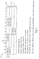
- the task message 100 comprises the following fields, TYPE 102, SRC 104, G_NUM 106, HEAD_PTR 108, TAIL_PTR 110, and MP_ID 112.
- the TYPE 102 field is the type of message.
- the TYPE 102 field defines the type of task wherein each task has a predefined path flow which specifies the order of the task blocks.
- the task manager 200 uses this information to route the task message 100.
- the SRC 104 field is the source task block 206 (Fig. 2). This SRC 104 field is used to specify the source inpu t port 202 of the task message 100.
- the TYPE 102 field is used by the task manager 200 to store the message into a corresponding input buffer 506 (FIG. 5) to prevent head -of-line blocking.
- the G_NUM 106 field specifies the number of granules of the corre sponding packet (not shown).
- the HEAD_PTR 108 and TAIL_PTR 110 fields are the Head and Tail Pointer of the corresponding packet (not shown).
- the MP_ID 112 field is a multipurpose ID field used to track the flow of the corresponding packet (not shown). It should be noted that Message and Packet as defined herein are different.
- a Message as defined herein means an identification of the packet. Because it is not practical to transport the packet among the task blocks, each packet is assigned an identification that is called Message and message is used as a way to pass the packet information among the Task blocks.
- the task manager 200 uses the message TYPE 102 field and its internal look -up table, LURAM 504 (FIG 5), to route the message to the task blocks 206.
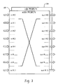
- the task manager 200 has two separate switch planes 302, 304 as shown in FIG 3.
- the two switch planes 302 and 304 perform the identical functions.
- One of the switch planes 302 is used for high priority traffic, and the other 304 is used for low priority traffic.
- Switch plane 302 comprises its own ready_h line 208a, a write_h line 208b, a ready_h line 210a, and a read_h line 210b.
- the other switch plane 304 comprises its own a ready_l line 208c, a write_l line 208d, a ready_l line 210c, and a read_l line 210d. Only the data bus 208e and 210e are shared between switch planes 302 and 304
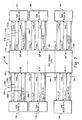
- the task manager 200 is comprised of a plurality of ports 402. Each port 402 has an input port 202 and an o utput port 204. Forwarding of messages from an input port 202 to an output port 204 is coordinated by an arbitration state machine 406.
- One function of the arbitration state machine 406 is to prevent more than one input port 202 from forwarding messages to the same output port 204.
- the arbitration state machine 406 uses a round -robin scheme wherein every input port 202 has equal access. This functionality may be implemented via a multiplexer or other standard switching equipment well known i n the art.
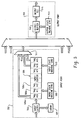
- Each input port 202 comprises input buffers 506, an input latch 502, a lookup RAM (LURAM) 504, and two input state machine (STM1) 508 and (STM2) 510.
- LURAM lookup RAM
- the input buffer 506 is a RAM based buffer and is configurable and divided into pre - allocated segments 506a, 506b, 506c.
- the segment is used to store messages before forwarding to the output port's 204 output bu ffer 512.
- the Host/CPU can dynamically allocate and configure each individual segment with a different amount of space to accommodate the traffic burst behavior of each input port 202.
- Each of the input buffer's 202 pre-allocated segments 506a, 506b, and 506c is a dedicated space to hold messages for an assigned output port 204.
- segment 1 506a is a space to hold messages for output port 1 (not shown)
- segment #2 506b is a space to hold messages for output port #2 (not shown).
- By providing multiple segments to store message within the input buffer 202 It can prevent head -of-line blocking. For example, when an input port's 202 traffic is bursty or the destination output port 204 is busy, this can cause t he port's output buffer 512 to fill up. If there are more messages arriving and the messages are destined to other non-busy ports, then these messages can be processed by the task manager 200 because they can be stored in the other segments. Otherwise, w hen the output buffer 512 is full, the output buffer 512 will stop accepting messages from the input port 202 and eventually the input port 202 will send back pressure to the source task block 206.
- a task block's 206 message 100 is sent to the tas k manger's 200 input port 202, the message 100 is latched by the input latch 502 and the message TYPE field 102 is extracted and used as an index to the internal LURAM 504.
- the LURAM 504 table determines the message's 100 destination.
- the message 100 is then presorted and tagged with the destination and forwarded directly into the pre -allocated segment, e.g. 506a, within the input buffer 506 corresponding to the output port 204 of the message's 100 destination.
- STM1 508 handles the message flow at the input port 202 into the input buffer 506 while STM2 510 is responsible for moving the message out of the input buffer 506 and into the output port 2 04.
- the input buffer 506 is a RAM both STM1 508 and STM2 510 will have to coordinate with each other when sharing access to the input buffer 506 to avoid data contention.
- the input port's 202 STM2 510 has to request access to the output port 204.
- the access request is handled by the arbitration state machine 406, which grants equal access to all ports by using a round robin access scheme.
- Multiplexer 511 selects the a ppropriate pre-allocated segment for the output buffer 512 currently selected by the arbitration state machine 406. While one input port 202 is granted access to an output port 204, the remaining request input port's will have to wait for access.
- Another aspect of the present invention is the ability to optimize the message rate from a source block (206) (FIG 1) to an input port 202).
- Logic is implemented to predict how much time is available for STM1 508 to move a task block's 206 message to the inp ut buffer 506 before STM2 510 will obtain access to the input buffer 506.
- the arbitration state machine 406 uses a round -robin scheme wherein every input port 202 is given equal access, the time available for STM1 508 to move a task block's messag e to the input buffer 506 can be predicted by sampling all of the other input port's 202 and determining how many input ports 202 have messages to be moved to an output port 204.
- the predicted time can be computed by 5 clocks x 7.5 nS x # request pending ports. The predict time allows the STM1 508 continuous to move message 100 into the input buffer 506.
- Each output port 204 has its own output buffer 512 which serves as a buffer to store messages before sending the messages to an output register 516 and to its destination task block 206 (FIG 2).
- the size of the output buffer 512 is configurable and can be act as a jitter buffer to control latency.
- An output state machine 514 routes the message from the output buffer 512 to its destination. When the output buffer 512 is full, it communicates to the input buffer 506 to indicate there is no space available and that no more messages will be accepted. Of course when the output buffer 512 again has space, it will communicate to the input buffer 506 to resume accepting messages.
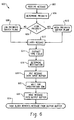
- the process 600 begins at step 602 when a message 100 is sent by a task block 206 to an input port 202.
- the message's 100 priority is determined by its control signals.
- the message 100 is routed according to its priori ty, if the message 100 is a high priority it is routed to the high priority switch plane 302, otherwise it is routed to the low priority switch plane 304. Because the switch planes 302, 304 perform the identical functions, the remaining steps are the same for either switch plane.
- a switch plane 302, 304 receives the message 100, it is latched as shown in step 612.
- the data in the TYPE 102 field of the message 100 is extracted.
- the LURAM 504 (FIG 5) is used to determine t he destination of the message 100.
- the message is then forwarded by STM1 508 into the appropriate pre -allocated segment appropriate for the destination, e.g. either 506a, 506b, 506c, etc. of the input buffer 506, as shown in step 618.
- the message 100 waits in the input buffer 506 until the arbitration state machine 406 polls the input buffer 506.
- the message 100 is moved by input state machine 510 via multiplexer 511 into the output buffer 512.
- a task block 206 at the destination then removes the message 100 from the output buffer at step 624.
Landscapes
- Engineering & Computer Science (AREA)
- Software Systems (AREA)
- Theoretical Computer Science (AREA)
- Physics & Mathematics (AREA)
- General Engineering & Computer Science (AREA)
- General Physics & Mathematics (AREA)
- Data Exchanges In Wide-Area Networks (AREA)
Applications Claiming Priority (2)
| Application Number | Priority Date | Filing Date | Title |
|---|---|---|---|
| US262308 | 1994-06-20 | ||
| US10/262,308 US20030163595A1 (en) | 2002-02-26 | 2002-10-01 | Task manager - method of forwarding messages among task blocks |
Publications (2)
| Publication Number | Publication Date |
|---|---|
| EP1418505A2 true EP1418505A2 (de) | 2004-05-12 |
| EP1418505A3 EP1418505A3 (de) | 2006-07-26 |
Family
ID=32106380
Family Applications (1)
| Application Number | Title | Priority Date | Filing Date |
|---|---|---|---|
| EP03103598A Withdrawn EP1418505A3 (de) | 2002-10-01 | 2003-09-29 | Taskverwalter - Verfahren zum Weiterleiten von Nachrichten zwischen Taskblöcken |
Country Status (2)
| Country | Link |
|---|---|
| US (1) | US20030163595A1 (de) |
| EP (1) | EP1418505A3 (de) |
Cited By (2)
| Publication number | Priority date | Publication date | Assignee | Title |
|---|---|---|---|---|
| CN101087256B (zh) * | 2007-07-13 | 2011-08-17 | 杭州华三通信技术有限公司 | 报文传输方法及系统 |
| US8307139B1 (en) * | 2003-03-14 | 2012-11-06 | Marvell International Ltd. | Method and apparatus for dynamically granting access of a shared resource among a plurality of requestors |
Families Citing this family (5)
| Publication number | Priority date | Publication date | Assignee | Title |
|---|---|---|---|---|
| US6424969B1 (en) * | 1999-07-20 | 2002-07-23 | Inmentia, Inc. | System and method for organizing data |
| US6944619B2 (en) * | 2001-04-12 | 2005-09-13 | Primentia, Inc. | System and method for organizing data |
| US6804525B2 (en) * | 2002-04-02 | 2004-10-12 | Motorola, Inc. | Method and apparatus for facilitating two-way communications between vehicles |
| US20040158561A1 (en) * | 2003-02-04 | 2004-08-12 | Gruenwald Bjorn J. | System and method for translating languages using an intermediate content space |
| US8407710B2 (en) * | 2010-10-14 | 2013-03-26 | International Business Machines Corporation | Systems and methods for dynamically scanning a plurality of active ports for priority schedule of work |
Family Cites Families (18)
| Publication number | Priority date | Publication date | Assignee | Title |
|---|---|---|---|---|
| US4333144A (en) * | 1980-02-05 | 1982-06-01 | The Bendix Corporation | Task communicator for multiple computer system |
| US4814979A (en) * | 1981-04-01 | 1989-03-21 | Teradata Corporation | Network to transmit prioritized subtask pockets to dedicated processors |
| US4412285A (en) * | 1981-04-01 | 1983-10-25 | Teradata Corporation | Multiprocessor intercommunication system and method |
| US5438680A (en) * | 1988-04-29 | 1995-08-01 | Intellectual Properties And Technology, Inc. | Method and apparatus for enhancing concurrency in a parallel digital computer |
| US5157654A (en) * | 1990-12-18 | 1992-10-20 | Bell Communications Research, Inc. | Technique for resolving output port contention in a high speed packet switch |
| JP3717951B2 (ja) * | 1993-03-02 | 2005-11-16 | ヒューレット・パッカード・カンパニー | デッドロック回避システムおよび方法 |
| US5774731A (en) * | 1995-03-22 | 1998-06-30 | Hitachi, Ltd. | Exclusive control method with each node controlling issue of an exclusive use request to a shared resource, a computer system therefor and a computer system with a circuit for detecting writing of an event flag into a shared main storage |
| US5517495A (en) * | 1994-12-06 | 1996-05-14 | At&T Corp. | Fair prioritized scheduling in an input-buffered switch |
| JPH08185380A (ja) * | 1994-12-28 | 1996-07-16 | Hitachi Ltd | 並列計算機 |
| US6539435B2 (en) * | 1995-06-21 | 2003-03-25 | International Business Machines Corporation | System and method for establishing direct communication between parallel programs |
| US6052373A (en) * | 1996-10-07 | 2000-04-18 | Lau; Peter S. Y. | Fault tolerant multicast ATM switch fabric, scalable speed and port expansion configurations |
| JPH10254843A (ja) * | 1997-03-06 | 1998-09-25 | Hitachi Ltd | クロスバスイッチ、該クロスバスイッチを備えた並列計算機及びブロードキャスト通信方法 |
| US6012084A (en) * | 1997-08-01 | 2000-01-04 | International Business Machines Corporation | Virtual network communication services utilizing internode message delivery task mechanisms |
| US6434115B1 (en) * | 1998-07-02 | 2002-08-13 | Pluris, Inc. | System and method for switching packets in a network |
| US6286026B1 (en) * | 1998-08-17 | 2001-09-04 | Xerox Corporation | Method and apparatus for integrating pull and push tasks in pipeline data processing |
| US6961781B1 (en) * | 2000-08-31 | 2005-11-01 | Hewlett-Packard Development Company, L.P. | Priority rules for reducing network message routing latency |
| US6925537B2 (en) * | 2001-06-11 | 2005-08-02 | Hewlett-Packard Development Company, L.P. | Multiprocessor cache coherence system and method in which processor nodes and input/output nodes are equal participants |
| US6839896B2 (en) * | 2001-06-29 | 2005-01-04 | International Business Machines Corporation | System and method for providing dialog management and arbitration in a multi-modal environment |
-
2002
- 2002-10-01 US US10/262,308 patent/US20030163595A1/en not_active Abandoned
-
2003
- 2003-09-29 EP EP03103598A patent/EP1418505A3/de not_active Withdrawn
Cited By (3)
| Publication number | Priority date | Publication date | Assignee | Title |
|---|---|---|---|---|
| US8307139B1 (en) * | 2003-03-14 | 2012-11-06 | Marvell International Ltd. | Method and apparatus for dynamically granting access of a shared resource among a plurality of requestors |
| US9037767B1 (en) | 2003-03-14 | 2015-05-19 | Marvell International Ltd. | Method and apparatus for dynamically granting access of a shared resource among a plurality of requestors |
| CN101087256B (zh) * | 2007-07-13 | 2011-08-17 | 杭州华三通信技术有限公司 | 报文传输方法及系统 |
Also Published As
| Publication number | Publication date |
|---|---|
| EP1418505A3 (de) | 2006-07-26 |
| US20030163595A1 (en) | 2003-08-28 |
Similar Documents
| Publication | Publication Date | Title |
|---|---|---|
| US4991172A (en) | Design of a high speed packet switching node | |
| US6633580B1 (en) | N×N crossbar packet switch | |
| US8352669B2 (en) | Buffered crossbar switch system | |
| US7773622B2 (en) | Deferred queuing in a buffered switch | |
| US20050036502A1 (en) | System and method for handling multicast traffic in a shared buffer switch core collapsing ingress VOQ's | |
| US20020064156A1 (en) | Switching arrangement and method | |
| CN116235469B (zh) | 网络芯片和网络设备 | |
| US5051985A (en) | Contention resolution in a communications ring | |
| EP1418505A2 (de) | Taskverwalter - Verfahren zum Weiterleiten von Nachrichten zwischen Taskblöcken | |
| US20020146033A1 (en) | Self-route multi-memory packet switch adapted to have an expandable number of input/output ports | |
| US8040907B2 (en) | Switching method | |
| US7206857B1 (en) | Method and apparatus for a network processor having an architecture that supports burst writes and/or reads | |
| WO1999029071A1 (en) | Resource sharing | |
| US7269158B2 (en) | Method of operating a crossbar switch | |
| US7424027B2 (en) | Head of line blockage avoidance system and method of operation thereof | |
| JP2002199000A (ja) | カスケード接続された制御部及びバッファ無しのカスケード接続されたスイッチング・マトリクスを有するパケット交換装置 | |
| US7254139B2 (en) | Data transmission system with multi-memory packet switch | |
| US7020149B1 (en) | Method for operating a switching system for data packets | |
| US7339943B1 (en) | Apparatus and method for queuing flow management between input, intermediate and output queues | |
| US7142515B2 (en) | Expandable self-route multi-memory packet switch with a configurable multicast mechanism | |
| KR100787225B1 (ko) | 입력버퍼장치 및 입력버퍼장치의 제어방법 | |
| US7130302B2 (en) | Self-route expandable multi-memory packet switch | |
| JPH0927812A (ja) | Atmスイッチのアドレス生成回路 | |
| JP2989263B2 (ja) | 高速データパケットスイッチング回路および方法 | |
| Kim et al. | A high-speed ATM switch architecture using random access input buffers and multi-cell-time arbitration |
Legal Events
| Date | Code | Title | Description |
|---|---|---|---|
| PUAI | Public reference made under article 153(3) epc to a published international application that has entered the european phase |
Free format text: ORIGINAL CODE: 0009012 |
|
| AK | Designated contracting states |
Kind code of ref document: A2 Designated state(s): AT BE BG CH CY CZ DE DK EE ES FI FR GB GR HU IE IT LI LU MC NL PT RO SE SI SK TR |
|
| AX | Request for extension of the european patent |
Extension state: AL LT LV MK |
|
| RAP1 | Party data changed (applicant data changed or rights of an application transferred) |
Owner name: ZARLINK SEMICONDUCTOR LIMITED |
|
| PUAL | Search report despatched |
Free format text: ORIGINAL CODE: 0009013 |
|
| AK | Designated contracting states |
Kind code of ref document: A3 Designated state(s): AT BE BG CH CY CZ DE DK EE ES FI FR GB GR HU IE IT LI LU MC NL PT RO SE SI SK TR |
|
| AX | Request for extension of the european patent |
Extension state: AL LT LV MK |
|
| AKX | Designation fees paid | ||
| REG | Reference to a national code |
Ref country code: DE Ref legal event code: 8566 |
|
| STAA | Information on the status of an ep patent application or granted ep patent |
Free format text: STATUS: THE APPLICATION IS DEEMED TO BE WITHDRAWN |
|
| 18D | Application deemed to be withdrawn |
Effective date: 20070127 |