EP1418543A2 - Kontrastausgleich in einem Digitalbild mittels Histogrammentzerrung - Google Patents
Kontrastausgleich in einem Digitalbild mittels Histogrammentzerrung Download PDFInfo
- Publication number
- EP1418543A2 EP1418543A2 EP03025452A EP03025452A EP1418543A2 EP 1418543 A2 EP1418543 A2 EP 1418543A2 EP 03025452 A EP03025452 A EP 03025452A EP 03025452 A EP03025452 A EP 03025452A EP 1418543 A2 EP1418543 A2 EP 1418543A2
- Authority
- EP
- European Patent Office
- Prior art keywords
- value
- unit
- pixel values
- image signal
- pixel
- Prior art date
- Legal status (The legal status is an assumption and is not a legal conclusion. Google has not performed a legal analysis and makes no representation as to the accuracy of the status listed.)
- Granted
Links
Images





Classifications
-
- G—PHYSICS
- G06—COMPUTING OR CALCULATING; COUNTING
- G06T—IMAGE DATA PROCESSING OR GENERATION, IN GENERAL
- G06T5/00—Image enhancement or restoration
- G06T5/90—Dynamic range modification of images or parts thereof
- G06T5/92—Dynamic range modification of images or parts thereof based on global image properties
-
- H—ELECTRICITY
- H04—ELECTRIC COMMUNICATION TECHNIQUE
- H04N—PICTORIAL COMMUNICATION, e.g. TELEVISION
- H04N5/00—Details of television systems
- H04N5/44—Receiver circuitry for the reception of television signals according to analogue transmission standards
- H04N5/57—Control of contrast or brightness
-
- G—PHYSICS
- G06—COMPUTING OR CALCULATING; COUNTING
- G06T—IMAGE DATA PROCESSING OR GENERATION, IN GENERAL
- G06T5/00—Image enhancement or restoration
- G06T5/40—Image enhancement or restoration using histogram techniques
Definitions
- the present invention relates to a contrast compensation apparatus using histogram equalization and a method thereof, and more particularly, to a contrast compensation apparatus having a simplified hardware structure and a low contrast distortion and a method thereof.
- the basic principle of histogram equalization is to change features of a given image by varying a histogram of the image.
- a histogram shows a gray-level luminance distribution of an image.
- Such a gray-level histogram shows ratios of brightness to darkness, that is, contrast ratios, of an image, and the contrast ratios change when the histogram varies.
- contrast ratios ratios of brightness to darkness
- a high contrast ratio renders an image sharp
- a low contrast ratio renders an image blurry.
- FIG. 1A and FIG. 1C are views illustrating the contrast concept
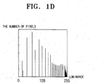
- FIG. 1 B and FIG. 1D are views illustrating histograms for FiG. 1A and FIG. 1 C, respectively.
- FIG. 1A and FiG. 1C illustrate an image and a contrast-enhanced image by histogram equalization, respectively.
- the distinct luminance contrast between individual pixels forming an image facilitates the recognition of an image.
- FiG. 1 B illustrates a histogram of luminance distribution for the image shown in FIG. 1A.
- FIG. 1B pixels are clustered around an area having a low luminance. Accordingly, the luminance differences among the respective pixels forming the image are small, making the image hardly recognizable.
- FIG. 1D illustrates a histogram for the image shown in FIG. 1C.
- the luminance in the histogram illustrated in FIG. 1B is ramified in an expanded form. Accordingly, the respective pixels forming the image have different degrees of luminance, making the image easily recognizable.
- FIG. 2 is a block diagram for showing a conventional contrast compensation device.
- the contrast compensation unit shown in FIG. 2 has a probability density function (PDF) calculation unit 10, a cumulative distribution function (CDF) calculation unit 20, and a mapping unit 30.
- PDF probability density function
- CDF cumulative distribution function
- the PDF calculation unit 10 detects luminance degrees of respective pixels forming an input image, and calculates a probability density function based on the detection.
- the probability density function is a function that graphs the number of pixels having a specified luminance.
- the mapping unit 30 tends to map low luminance values of pixels into high luminance values based on a cumulative distribution function obtained by Formula 1 when the overall luminance of an input image is high.
- FIG. 3A to FIG. 3H are views illustrating an image compensation process through the contrast compensation device of FIG. 2.
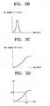
- FIG. 3A shows a night mountain image that looks dark on the whole. Accordingly, if a probability density function is expressed based on calculated luminance degrees of respective pixels forming the image of FIG. 3A, a distribution of a plurality of dark colors is seen as shown in FIG. 3B.
- FIG. 3C shows a cumulative distribution function obtained through Formula 1 for FIG. 3B, and FIG. 3D is obtained when the cumulative distribution function obtained for FIG. 3C is converted into a gray scale of 256 levels.
- FIG. 3D is used herein to illustrate a mapping function for mapping an image signal. For example, if the input image is dark overall and any one of the pixels forming the input image has 100 gray levels, the mapping unit 30 maps the image to have 80 gray levels.
- FIG. 3E if the moon C of high luminance emerges on the upper right side between night mountains A and the night sky B on an image, a probability density function is formed as shown in FIG. 3F.
- the left side of FIG. 3F indicates a distribution of pixels of low luminance, and the right side of the same indicates distribution of pixels of high luminance.
- a cumulative distribution function obtained for FIG. 3F based on Formula 1 is as shown in FIG. 3G.
- FIG. 3H is obtained when the accumulative distribution function of FIG. 3G is converted into a 256-level gray scale, and, when FIG.
- 3H is used as a mapping function, 100 gray levels are mapped into 120 gray levels, because a slope of the cumulative distribution function rapidly increases when the probability density function for the bright moon A is accumulated with the probability density function of FIG. 3F.
- FIG. 3H is used as a mapping function, an average luminance of all pixels forming the image increases. That is, not only is the position where the moon C emerges brightened, but the entire image also is brightened. Accordingly, the entire image has a high luminance, and the mountains A, sky B, and moon C become indistinct in luminance therebetween, and thus the image is blurred. That is, contrast ratios are degraded.
- an aspect of the present invention is to provide a contrast compensation apparatus having less contrast distortion than conventional hardware and having a simplified hardware structure, and a method thereof.
- a contrast compensation apparatus comprises a pixel value detection unit to detect a distribution of pixel values of respective pixels of an input image signal; a pixel value limit unit having pre-set luminance limit values, and to reconfigure the distribution of the pixel values of the respective pixels based on the pre-set luminance limit values; and a mapping unit to set a luminance for the respective pixels based on a cumulative distribution function with respect to the re-configured pixel values.
- the pre-set luminance limit values include a first setting value for setting an upper limit of the detected pixel values of the respective pixels; and a second setting value for setting a lower limit of the detected pixel values of the respective pixels.
- the pixel value limit unit includes a first comparison part to compare the pixel values of the respective pixels detected from the pixel value detection unit with a first setting value, and outputting the first setting value when the detected pixel values exceed the first setting value; and a second comparison part to compare the pixel values of the respective pixels detected from the pixel value detection unit with a second setting value, and outputting the second setting value when the detected pixel values of the respective pixels are smaller than the second setting value.
- the first comparison part includes a first buffer having an input terminal from which an image signal is inputted, and an output terminal connected to an output terminal of the first comparison part; a first storage to store the first setting value; and a first comparator to compare the image signal with the first setting value of the first storage, and enable either the first buffer or the first storage based on a result of the comparison.
- the second comparison part includes a second buffer having an input terminal from which an image signal is inputted, and an output terminal connected to an output terminal of the second comparison part; a second storage to store the second setting value; and a second comparator to compare the image signal with the second setting value of the second storage, and enable either the second buffer or the second storage based on a result of the comparison.
- a contrast compensation method comprises operations of calculating pixel values of an image signal; limiting the calculated pixel values based on pre-set luminance limit values, and re-configuring the calculated pixel values of the image signal; and calculating a cumulative distribution function for the reconfigured pixel values, and setting a contrast of the image signal based on the cumulative distribution function.
- the operation to reconfigure the pixel values includes operations of setting an upper limit value of the calculated pixel values; setting a lower limit value of the calculated pixel values; and mapping pixel values over the upper limit value and pixel values under the lower limit value into the upper limit value and the lower limit value, respectively.
- the operation to set the contrast of the image signal includes operations of converting the cumulative distribution function into a predetermined gray level; and mapping the pixel values of the image signal based on the cumulative distribution function converted to the gray level.
- the mapping operation includes operations of dividing the cumulative distribution function by the number of pixels forming the image signal; and multiplying, by the predetermined gray level, the cumulative distribution function divided by the number of pixels.
- FIG. 4 is a block diagram schematically representing a contrast compensation apparatus according to an embodiment of the present invention.
- the contrast compensation apparatus in the embodiment illustrated in FIG. 4 has a PDF calculation unit 100, a luminance value limit/restraint unit (or Bit Under threshold Bit over threshold (BUBO) unit) 200, a CDF unit 300, a CDF compensation unit 400, and a mapping unit 500.
- BUBO Bit Under threshold Bit over threshold
- the PDF unit 100 detects a pixel value distribution of an input image, and calculates a probability density function (PDF) based on the distribution.
- PDF probability density function
- the probability density function is defined as in previous Formula 1.
- the pixel value can be the luminance value, a grayscale value of three primary colors R, G, B, or a grayscale value of color difference signals Y, Cb, Cr. Representing the grayscale value by 8-bits will render the primary colors R, G, B and the saturation in 256 levels (i.e., 2 8 levels).
- the luminance value can also be expressed by 256 levels, and the color difference signals Y, Cb, Cr can be expressed by 8 bits, respectively. Accordingly, the luminance value, grayscale value of the primary color signals and grayscale value of the color difference signal are varied in accordance with the variation of the brightness value by the input image signal, and the PDF corresponding to the variation of luminance of input image signal can be calculated.
- the contrast compensation apparatus according to the present invention will be described mainly with reference to the luminance value of the input image signal.
- the present invention is equally applicable to the grayscale values of the three primary colors R, G, B and the color difference signals.
- the BUBO unit 200 contains a first setting value to set over-threshold values (or values over an upper limit value) of the detected luminance value and a second setting value to set under-threshold values (or values under a lower limit value) of the detected luminance value, and maps luminance values over the first setting value or under the second setting value, out of the luminance values detected from the PDF calculation unit 100, into the first setting value or the second setting value.
- the BUBO unit 200 when the first and second setting values are set to a 20-level gray scale and a 200-level gray scale, respectively, for an input image having 256 gray levels (0 ⁇ 255 gray levels), the BUBO unit 200 outputs a 20- to 200-level image as is to the CDF calculation unit 300, whereas the BUBO unit 200 maps the luminance values under 20-level gray scale (for example, 15) into the 20-level gray scale, and luminance values over 200-level gray scale (for example, 210) into the 200-level gray scale, before outputting to the CDF calculation unit 300.
- the luminance values thusly, even though certain image portions have excessively high or low luminance values, the luminance of an entire image may be prevented from being excessively high or low when an image is displayed.
- the CDF calculation unit 300 sequentially accumulates and calculates probability density functions outputted from the BUBO unit 200. Then, a cumulative distribution function is defined as in previous Formula 2.
- the CDF compensation unit 400 divides a cumulative calculation value outputted from the CDF calculation unit 300 by the number of pixels forming an image to obtain an average value. This process will be described in detail later.
- FIG. 5 is an illustrative block diagram for an embodiment of the BUBO unit 200 shown in FIG. 4.
- the BUBO unit 200 shown in FIG. 5 has a first comparison part 210 and a second comparison part 220.
- the first comparison part 210 compares a first setting value with a luminance value detected from the PDF calculation unit 100, and, if the detected luminance value exceeds the first setting value as a result of the comparison, outputs the first setting value. If the detected luminance value does not exceed the first setting value, the first comparison part 210 outputs the detected luminance value to the second comparison part 220.
- the second comparison part 220 compares a second setting value with a luminance value detected from the BUBO unit 200, and, if the luminance value is smaller than the second setting value as a result of the comparison, outputs the second setting value. If the luminance value is larger than the second setting value, the detected luminance value is outputted to the CDF calculation unit 300.
- the first comparison part 210 has a first setting value storage (first storage) 211, a first comparator 212, and a first buffer 213.
- the first setting value storage (first storage) 211 stores a first setting value, and is enabled when logic "high” is outputted from the first comparator 212.
- the first comparator 212 compares a luminance value detected from the PDF calculation unit 100 with the first setting value stored in the first setting value storage (first storage) 211. If the detected luminance value does not exceed the first setting value as a result of the comparison, the first comparator 212 outputs logic "low". Accordingly, the first buffer 213 is enabled so that the detected luminance value is outputted to the second comparison part 220.
- logic "high” is outputted to enable the first setting value storage (first storage) 211, and the first setting value stored in the first setting value storage (first storage) 211 is outputted to the second comparison unit 220.
- the second comparison part 220 has a second setting value storage (second storage) 221, a second comparator 222, and a second buffer 223.
- the second setting value storage (second storage) 221 stores a second setting value, and is enabled when the second comparator 222 outputs logic "high”.
- the second comparator 222 compares the second setting value with a luminance value outputted from the first comparison part 210. If the applied luminance value is smaller than the second setting value as a result of the comparison, the second comparator 222 outputs logic "low", and, if the applied luminance value is larger than the second setting value, outputs logic "high".
- an output value of the second comparator 222 is logic "low”
- an output value of the first comparison part 210 is outputted from the CDF calculation unit 300
- the output value of the second comparator 222 is logic "high”
- the second setting value is outputted to the CDF calculation unit 300.
- FIG. 6A and FIG. 6B are views schematically illustrating the operation of the first and second comparison parts 210 and 220 in FIG. 5, respectively.
- FIG. 6A is a view illustrating the operation of the first comparison part 210 of FIG 5, wherein (1) of FIG. 6 A denotes a probability density function of an image, (2) of FIG. 6 A denotes a portion having luminance values larger than a first setting value, and (3) of FIG. 6A denotes mapping the luminance values over the first setting value which have been mapped into the first setting value.
- FIG. 6B is a view illustrating operations of the second comparison part 220 of FIG. 4, wherein (1) of FIG. 6B denotes a probability density function of an image, (2) of FIG. 6B denotes luminance values smaller than the second setting value, and (3) of FIG. 6B denotes the luminance values smaller than the second setting value which have been mapped into the second setting value.
- the contrast compensation apparatus according to the schematics shown in FIG. 6A and FIG. 6B reduces the influence on the luminance of an entire image due to luminance of specified portions forming the image.
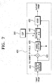
- FIG. 7 is a block diagram illustrating an embodiment of the CDF compensation unit 400 of FIG. 4 in detail.
- the CDF compensation unit 400 has a luminance value detector 410, a multiplier 420, a barrel shifter 430, a subtractor 440, and an adder 450.
- the luminance detector 410 inputs an image and detects a luminance Value of the inputted image.
- the multiplexer 420 multiplies the luminance value detected from the luminance value detector 410 by the number of pixels used to form a selected image from the inputted image.
- the barrel shifter 430 shifts an image signal outputted from the multiplexer 420 by the number of luminance (i.e., luminance value), for example, 255, used to form the selected image.
- the shift operations of the barrel shifter 430 herein act as a divider that divides the output of the multiplexer 420 by the number of the luminance.
- the subtractor 440 inputs an output of the CDF calculation unit 300 and an output of the barrel shifter 430, and calculates a difference between the output of the CDF calculation unit 300 and the output of the barrel shifter 430.
- the adder 450 adds the luminance value detected from the luminance value detector 410 and the output of the subtractor 440.
- a lowest value of a luminance signal is "1", and the highest value is "4".
- the luminance values are limited to, for example, 4 kinds for simplicity but, actually, the luminance signal has a 256-level (0 ⁇ 255) luminance.
- the above values indicate that the number of pixels having a luminance value of "1" is 4, the number of pixels having a luminance value of "2" is 8, the number of pixels having a luminance value of "3” is 8, and the number of pixels having a luminance value of "4" is 13.
- CDF ⁇ 1 ⁇ 4
- CDF ⁇ 2 ⁇ 12
- CDF ⁇ 3 ⁇ 20
- CDF ⁇ 4 ⁇ 33
- CDF ⁇ 2 ⁇ PDF ⁇ 1 ⁇ + PDF ⁇ 2 ⁇
- CDF ⁇ 4 ⁇ PDF ⁇ 1 ⁇ + PDF ⁇ 2 ⁇ + PDF ⁇ 3 ⁇ + PDF ⁇ 4 ⁇ .
- the cumulative distribution functions re-configured as above are stored in the mapping unit 500 as a look-up table.
- the contrast compensation apparatus maps and outputs luminance values of an image signal according to the reconfigured cumulative distribution functions. For example, if the luminance values of an image signal are 1, 2, and 3, the values are mapped to a luminance value "1" for outputs, and a luminance value "4" is outputted only when the luminance value of an image signal is "4". Accordingly, when an image signal is converted into an image, the entire image does not become bright even though the image mainly has the high luminance value "4", which would degrade its contrast ratio.
- the implementation of Formula 2 in hardware requires an adder, a subtractor, a multiplier, and a divider, but the barrel shifter 430 is used as the divider in implementing the contrast compensation apparatus, so that the hardware structure is greatly reduced.
- a shift amount in the barrel shifter 430 is decided based on a displayable maximum luminance value "N", and, upon general contrast compensation, the value "N" becomes "255".
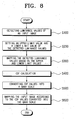
- FIG. 8 is a flow chart illustrating operations of a contrast compensation method according to an embodiment of the present invention.
- the PDF calculation unit 100 detects pixel values of an inputted image signal, and calculates probability density functions based on the pixel values (S100).
- the pixel value can be the luminance value, a grayscale value of three primary colors R, G, B, or a grayscale value of color difference signals Y, Cb, Cr. Representing the grayscale value by 8-bits will render the primary colors R, G, B and the saturation in 256 levels (i.e., 2 8 levels).
- the luminance value can also be expressed by 256 levels, and the color difference signals Y, Cb, Cr can be expressed by 8 bits, respectively.
- the luminance value, grayscale value of the primary color signals and grayscale value of the color difference signal are varied in accordance with the variation of the luminance value by the input image signal, and the PDF corresponding to the variation of luminance of input image signal can be calculated.
- the contrast compensation apparatus according to the present invention will be described mainly with reference to the luminance value of the input image signal.
- the present invention is equally applicable to the grayscale values of the three primary colors R, G, B and the color difference signals.
- an over-threshold value and an under-threshold value are set to remove luminance values such as "0" or "255" that greatly affect the luminance values of an entire image compared to a portion occupied on the image, that is, luminance values rendering the image excessively dark or bright (S200).
- the over-threshold values and the under-threshold values may be set to 10% from the highest luminance value and 10% from the lowest luminance value, respectively, but such values are not fixed, but vary when an image is rendered dark or bright.
- the conversion method into a gray scale and the mapping method based on the probability distribution function (LUT) are well-known technologies, so descriptions will be omitted. Accordingly, when certain portions of an image are rendered very bright or dark, the phenomenon in which the entire image becomes bright or dark may be reduced by the upper limit value and the lower limit value.
- the contrast compensation apparatus only uses the minimum number of multipliers, adders, and subtractors, so that the structure is simplified, and less electric power is consumed when the apparatus is implemented in hardware.
Landscapes
- Engineering & Computer Science (AREA)
- Physics & Mathematics (AREA)
- General Physics & Mathematics (AREA)
- Theoretical Computer Science (AREA)
- Multimedia (AREA)
- Signal Processing (AREA)
- Image Processing (AREA)
- Facsimile Image Signal Circuits (AREA)
- Picture Signal Circuits (AREA)
Applications Claiming Priority (2)
| Application Number | Priority Date | Filing Date | Title |
|---|---|---|---|
| KR2002068898 | 2002-11-07 | ||
| KR1020020068898A KR20040040699A (ko) | 2002-11-07 | 2002-11-07 | 콘트라스트 보정 장치 및 방법 |
Publications (3)
| Publication Number | Publication Date |
|---|---|
| EP1418543A2 true EP1418543A2 (de) | 2004-05-12 |
| EP1418543A3 EP1418543A3 (de) | 2004-11-24 |
| EP1418543B1 EP1418543B1 (de) | 2008-05-07 |
Family
ID=32105678
Family Applications (1)
| Application Number | Title | Priority Date | Filing Date |
|---|---|---|---|
| EP03025452A Expired - Lifetime EP1418543B1 (de) | 2002-11-07 | 2003-11-05 | Kontrastausgleich in einem Digitalbild mittels Histogrammentzerrung |
Country Status (6)
| Country | Link |
|---|---|
| US (1) | US7359573B2 (de) |
| EP (1) | EP1418543B1 (de) |
| JP (1) | JP2004159344A (de) |
| KR (1) | KR20040040699A (de) |
| CN (1) | CN1302436C (de) |
| DE (1) | DE60320735D1 (de) |
Cited By (5)
| Publication number | Priority date | Publication date | Assignee | Title |
|---|---|---|---|---|
| US7573533B2 (en) | 2004-10-15 | 2009-08-11 | Genesis Microchip Inc. | Method of generating transfer curves for adaptive contrast enhancement |
| US7760961B2 (en) * | 2004-10-15 | 2010-07-20 | Caba Moldvai | Adaptive contrast enhancement |
| US7936920B2 (en) | 2004-10-25 | 2011-05-03 | Athentech Technologies Inc | Method and apparatus for multiple data channel analysis using relative strength histograms |
| CN103137098A (zh) * | 2011-12-02 | 2013-06-05 | 联咏科技股份有限公司 | 色调对应方法及图像处理装置 |
| CN114511455A (zh) * | 2021-12-31 | 2022-05-17 | 上海盈方微电子有限公司 | 一种基于累计直方图的实时色调映射方法 |
Families Citing this family (30)
| Publication number | Priority date | Publication date | Assignee | Title |
|---|---|---|---|---|
| US7483083B2 (en) * | 2003-04-16 | 2009-01-27 | Intervideo, Inc. | Movie enhancement |
| KR100513273B1 (ko) * | 2003-07-04 | 2005-09-09 | 이디텍 주식회사 | 동영상 신호의 실시간 밝기 제어 장치 및 방법 |
| JP4610182B2 (ja) * | 2003-12-05 | 2011-01-12 | 株式会社日立ハイテクノロジーズ | 走査型電子顕微鏡 |
| JP4289225B2 (ja) * | 2004-06-18 | 2009-07-01 | 株式会社ニコン | 画像処理装置および画像処理方法 |
| US7760210B2 (en) * | 2005-05-04 | 2010-07-20 | Honeywood Technologies, Llc | White-based power savings |
| US7609244B2 (en) * | 2005-06-30 | 2009-10-27 | Lg. Display Co., Ltd. | Apparatus and method of driving liquid crystal display device |
| CN100550980C (zh) * | 2005-08-22 | 2009-10-14 | 广达电脑股份有限公司 | 影像传感器的周边暗角补偿方法及其装置 |
| KR100756318B1 (ko) * | 2006-01-16 | 2007-09-06 | 삼성전자주식회사 | 이득 조절 가능한 절단 빈도함수 평활화를 이용한 영상처리 방법 및 시스템 |
| US7865032B2 (en) * | 2006-09-22 | 2011-01-04 | Hewlett-Packard Development Company, L.P. | Methods and systems for identifying an ill-exposed image |
| TWI351212B (en) * | 2006-12-28 | 2011-10-21 | Altek Corp | Brightness adjusting method |
| WO2009072207A1 (ja) * | 2007-12-06 | 2009-06-11 | Fujitsu Limited | 画像補正装置、画像補正プログラムおよび画像補正方法 |
| JP5181970B2 (ja) * | 2008-09-25 | 2013-04-10 | オムロン株式会社 | 画像処理装置および画像処理方法 |
| TW201027407A (en) * | 2009-01-13 | 2010-07-16 | Quanta Comp Inc | Light compensation method |
| JP4575501B2 (ja) * | 2009-02-26 | 2010-11-04 | 株式会社東芝 | 映像信号処理装置及びその制御方法及びテレビジョン信号受信装置 |
| JP2010278724A (ja) * | 2009-05-28 | 2010-12-09 | Olympus Corp | 画像処理装置、画像処理方法及び画像処理プログラム |
| FR2947082B1 (fr) * | 2009-06-22 | 2014-12-12 | St Ericsson France Sas | Procede et dispositif de traitement d'une image numerique pour eclaircir ladite image. |
| TWI408619B (zh) * | 2009-11-16 | 2013-09-11 | Inst Information Industry | 影像對比提昇裝置及其方法 |
| TWI423166B (zh) * | 2009-12-04 | 2014-01-11 | Huper Lab Co Ltd | 判斷輸入影像是否為霧化影像之方法、判斷輸入影像的霧級數之方法及霧化影像濾清方法 |
| US8781248B2 (en) * | 2010-01-28 | 2014-07-15 | Stmicroelectronics Asia Pacific Pte. Ltd. | Image details preservation and enhancement |
| US8600190B1 (en) * | 2010-07-29 | 2013-12-03 | Exelis, Inc. | Method for combining two image data sets using fixed distribution |
| KR101851577B1 (ko) * | 2012-09-17 | 2018-04-24 | 삼성전자주식회사 | 유기 발광 다이오드 디스플레이의 동작을 제어할 수 있는 방법들과 장치들 |
| CN104282291A (zh) * | 2013-07-08 | 2015-01-14 | 联咏科技股份有限公司 | 图像处理装置及应用其的图像处理方法 |
| KR102196912B1 (ko) * | 2014-02-13 | 2020-12-31 | 삼성디스플레이 주식회사 | 표시장치 및 그 구동방법 |
| KR102157245B1 (ko) * | 2014-02-18 | 2020-09-18 | 삼성디스플레이 주식회사 | 광원 구동 방법 및 이를 수행하기 위한 표시 장치 |
| CN105184754B (zh) * | 2015-09-25 | 2018-03-06 | 深圳市华星光电技术有限公司 | 图像对比度增强方法 |
| CN106557729B (zh) * | 2015-09-30 | 2021-12-21 | 日本电气株式会社 | 用于处理人脸图像的设备和方法 |
| KR102524671B1 (ko) * | 2018-01-24 | 2023-04-24 | 삼성전자주식회사 | 전자 장치 및 그의 제어 방법 |
| US11398017B2 (en) | 2020-10-09 | 2022-07-26 | Samsung Electronics Co., Ltd. | HDR tone mapping based on creative intent metadata and ambient light |
| US11526968B2 (en) | 2020-11-25 | 2022-12-13 | Samsung Electronics Co., Ltd. | Content adapted black level compensation for a HDR display based on dynamic metadata |
| US20220237755A1 (en) * | 2021-01-28 | 2022-07-28 | Novatek Microelectronics Corp. | Image enhancement method and image processing device |
Family Cites Families (24)
| Publication number | Priority date | Publication date | Assignee | Title |
|---|---|---|---|---|
| JP2768786B2 (ja) | 1990-02-20 | 1998-06-25 | キヤノン株式会社 | 画像読み取り装置 |
| JP2936791B2 (ja) * | 1991-05-28 | 1999-08-23 | 松下電器産業株式会社 | 階調補正装置 |
| US5289282A (en) | 1991-05-28 | 1994-02-22 | Matsushita Electric Industrial Co., Ltd. | Video signal gradation corrector |
| JP3019479B2 (ja) | 1991-06-28 | 2000-03-13 | 松下電器産業株式会社 | 階調補正装置 |
| DE69229085T2 (de) * | 1991-07-12 | 1999-11-18 | Educational Testing Service, Princeton | System zur Bildverarbeitung |
| US5339368A (en) * | 1991-11-21 | 1994-08-16 | Unisys Corporation | Document image compression system and method |
| US5862234A (en) * | 1992-11-11 | 1999-01-19 | Todter; Chris | Active noise cancellation system |
| US5414538A (en) * | 1993-10-07 | 1995-05-09 | Xerox Corporation | Image-dependent exposure enhancement |
| US5982926A (en) * | 1995-01-17 | 1999-11-09 | At & T Ipm Corp. | Real-time image enhancement techniques |
| JP3501252B2 (ja) * | 1995-06-16 | 2004-03-02 | 三菱電機株式会社 | 階調補正装置 |
| US6463173B1 (en) | 1995-10-30 | 2002-10-08 | Hewlett-Packard Company | System and method for histogram-based image contrast enhancement |
| ES2185874T3 (es) * | 1996-04-10 | 2003-05-01 | Samsung Electronics Co Ltd | Procedimiento para mejorar la calidad de imagen mediante la ecualizacion de histograma por ajuste a la media y circuito para su realizacion. |
| EP0897634B1 (de) * | 1996-05-06 | 2005-02-02 | Cimatrix | Intelligente ccd-kamera mit progressiver abtastung |
| KR100189922B1 (ko) | 1996-06-20 | 1999-06-01 | 윤종용 | 히스토그램 등화를 이용한 동영상의 콘트라스트개선회로 및 그 방법 |
| US5949918A (en) * | 1997-05-21 | 1999-09-07 | Sarnoff Corporation | Method and apparatus for performing image enhancement |
| KR100243301B1 (ko) * | 1997-11-24 | 2000-02-01 | 윤종용 | 다이나믹 레인지 확대장치 및 방법 |
| US6714674B1 (en) * | 1998-04-30 | 2004-03-30 | General Electric Company | Method for converting digital image pixel values |
| KR100322596B1 (ko) * | 1998-12-15 | 2002-07-18 | 윤종용 | 입력 영상의 밝기를 유지하는 화질 개선 장치 및 그 방법 |
| KR100343692B1 (ko) * | 1998-12-31 | 2002-07-20 | 엘지전자주식회사 | 영상신호의 콘트라스트 향상장치 |
| US6504954B1 (en) * | 1999-02-05 | 2003-01-07 | Raytheon Company | Closed loop piecewise-linear histogram specification method and apparatus |
| AU769305B2 (en) * | 1999-03-31 | 2004-01-22 | Canon Kabushiki Kaisha | Image quality correcting circuit |
| DE50001023D1 (de) * | 1999-06-15 | 2003-02-06 | Infineon Technologies Ag | Verfahren und schaltungsanordnung zur kontrastverbesserung eines bildes |
| JP2002247393A (ja) | 2001-02-14 | 2002-08-30 | Konica Corp | 画像処理方法 |
| JP3992177B2 (ja) * | 2001-11-29 | 2007-10-17 | 株式会社リコー | 画像処理装置、画像処理方法及びコンピュータ・プログラム |
-
2002
- 2002-11-07 KR KR1020020068898A patent/KR20040040699A/ko not_active Withdrawn
-
2003
- 2003-11-04 US US10/699,658 patent/US7359573B2/en not_active Expired - Fee Related
- 2003-11-05 DE DE60320735T patent/DE60320735D1/de not_active Expired - Lifetime
- 2003-11-05 EP EP03025452A patent/EP1418543B1/de not_active Expired - Lifetime
- 2003-11-07 CN CNB2003101148173A patent/CN1302436C/zh not_active Expired - Fee Related
- 2003-11-07 JP JP2003379073A patent/JP2004159344A/ja active Pending
Cited By (6)
| Publication number | Priority date | Publication date | Assignee | Title |
|---|---|---|---|---|
| US7573533B2 (en) | 2004-10-15 | 2009-08-11 | Genesis Microchip Inc. | Method of generating transfer curves for adaptive contrast enhancement |
| US7760961B2 (en) * | 2004-10-15 | 2010-07-20 | Caba Moldvai | Adaptive contrast enhancement |
| US7936920B2 (en) | 2004-10-25 | 2011-05-03 | Athentech Technologies Inc | Method and apparatus for multiple data channel analysis using relative strength histograms |
| CN103137098A (zh) * | 2011-12-02 | 2013-06-05 | 联咏科技股份有限公司 | 色调对应方法及图像处理装置 |
| CN103137098B (zh) * | 2011-12-02 | 2015-06-17 | 联咏科技股份有限公司 | 色调对应方法 |
| CN114511455A (zh) * | 2021-12-31 | 2022-05-17 | 上海盈方微电子有限公司 | 一种基于累计直方图的实时色调映射方法 |
Also Published As
| Publication number | Publication date |
|---|---|
| US20040091169A1 (en) | 2004-05-13 |
| US7359573B2 (en) | 2008-04-15 |
| JP2004159344A (ja) | 2004-06-03 |
| EP1418543B1 (de) | 2008-05-07 |
| EP1418543A3 (de) | 2004-11-24 |
| CN1302436C (zh) | 2007-02-28 |
| KR20040040699A (ko) | 2004-05-13 |
| DE60320735D1 (de) | 2008-06-19 |
| CN1499441A (zh) | 2004-05-26 |
Similar Documents
| Publication | Publication Date | Title |
|---|---|---|
| EP1418543A2 (de) | Kontrastausgleich in einem Digitalbild mittels Histogrammentzerrung | |
| US6040860A (en) | Imaging apparatus for supplying images with rich gradation across the entire luminance range for all subject types | |
| US5517333A (en) | Gradation correction device and image sensing device therewith for supplying images with good gradation for both front-lit and back-lit objects | |
| JP3375921B2 (ja) | 入力映像の輝度を維持する画質改善装置及びその方法 | |
| US7570390B2 (en) | Image processing device and method | |
| CN108090879B (zh) | 一种对输入的高动态范围图像进行处理的方法和显示设备 | |
| US20010033260A1 (en) | Liquid crystal display device for displaying video data | |
| CN102438097B (zh) | 图像处理装置与图像处理方法 | |
| JP3130266B2 (ja) | 平均分離ヒストグラム等化を用いる映像改善方法及びその回路 | |
| EP0794513B1 (de) | Verfahren und Schaltungsanordnung zur Bildverbesserung durch verteilten Histogrammausgleich mit Hilfe einer quantisierten mittleren Bildhelligkeit | |
| US6259472B1 (en) | Histogram equalization apparatus for contrast enhancement of moving image and method therefor | |
| US7920183B2 (en) | Image processing device and digital camera | |
| JP4912398B2 (ja) | 画像処理装置、画像処理方法、プログラム、記録媒体および集積回路 | |
| US6137541A (en) | Image processing method and image processing apparatus | |
| US7643180B2 (en) | Image processing and display apparatus and method for tone resolution expansion of digital images | |
| US20080063295A1 (en) | Imaging Device | |
| US6768514B1 (en) | Image processing apparatus and image processing method | |
| JP5558240B2 (ja) | 画像処理装置 | |
| JPH09224174A (ja) | 積分ルックアップテーブルを用いる適応型ガンマ補正装置 | |
| JP2004007202A (ja) | 画像処理装置 | |
| KR20060081536A (ko) | 영상의 rgb 정보를 이용한 블랙/화이트 스트레칭 시스템 | |
| EP2541497A1 (de) | Vorrichtung, Methode, Programm und Speichermedium zur Bildverarbeitung | |
| JP2000102033A (ja) | 自動階調補正方法 | |
| JPH089197A (ja) | 画像表示装置 | |
| US20100189350A1 (en) | Image processing apparatus, image processing method, and program |
Legal Events
| Date | Code | Title | Description |
|---|---|---|---|
| PUAI | Public reference made under article 153(3) epc to a published international application that has entered the european phase |
Free format text: ORIGINAL CODE: 0009012 |
|
| 17P | Request for examination filed |
Effective date: 20031105 |
|
| AK | Designated contracting states |
Kind code of ref document: A2 Designated state(s): AT BE BG CH CY CZ DE DK EE ES FI FR GB GR HU IE IT LI LU MC NL PT RO SE SI SK TR |
|
| AX | Request for extension of the european patent |
Extension state: AL LT LV MK |
|
| PUAL | Search report despatched |
Free format text: ORIGINAL CODE: 0009013 |
|
| AK | Designated contracting states |
Kind code of ref document: A3 Designated state(s): AT BE BG CH CY CZ DE DK EE ES FI FR GB GR HU IE IT LI LU MC NL PT RO SE SI SK TR |
|
| AX | Request for extension of the european patent |
Extension state: AL LT LV MK |
|
| RIC1 | Information provided on ipc code assigned before grant |
Ipc: 7H 04N 5/20 B Ipc: 7G 06T 5/40 A |
|
| AKX | Designation fees paid |
Designated state(s): DE FR GB NL |
|
| GRAP | Despatch of communication of intention to grant a patent |
Free format text: ORIGINAL CODE: EPIDOSNIGR1 |
|
| GRAS | Grant fee paid |
Free format text: ORIGINAL CODE: EPIDOSNIGR3 |
|
| GRAA | (expected) grant |
Free format text: ORIGINAL CODE: 0009210 |
|
| AK | Designated contracting states |
Kind code of ref document: B1 Designated state(s): DE FR GB NL |
|
| REG | Reference to a national code |
Ref country code: GB Ref legal event code: FG4D |
|
| REF | Corresponds to: |
Ref document number: 60320735 Country of ref document: DE Date of ref document: 20080619 Kind code of ref document: P |
|
| PLBE | No opposition filed within time limit |
Free format text: ORIGINAL CODE: 0009261 |
|
| STAA | Information on the status of an ep patent application or granted ep patent |
Free format text: STATUS: NO OPPOSITION FILED WITHIN TIME LIMIT |
|
| 26N | No opposition filed |
Effective date: 20090210 |
|
| REG | Reference to a national code |
Ref country code: FR Ref legal event code: PLFP Year of fee payment: 14 |
|
| PGFP | Annual fee paid to national office [announced via postgrant information from national office to epo] |
Ref country code: FR Payment date: 20161025 Year of fee payment: 14 Ref country code: GB Payment date: 20161021 Year of fee payment: 14 Ref country code: NL Payment date: 20161021 Year of fee payment: 14 Ref country code: DE Payment date: 20161020 Year of fee payment: 14 |
|
| REG | Reference to a national code |
Ref country code: DE Ref legal event code: R119 Ref document number: 60320735 Country of ref document: DE |
|
| REG | Reference to a national code |
Ref country code: NL Ref legal event code: MM Effective date: 20171201 |
|
| GBPC | Gb: european patent ceased through non-payment of renewal fee |
Effective date: 20171105 |
|
| REG | Reference to a national code |
Ref country code: FR Ref legal event code: ST Effective date: 20180731 |
|
| PG25 | Lapsed in a contracting state [announced via postgrant information from national office to epo] |
Ref country code: NL Free format text: LAPSE BECAUSE OF NON-PAYMENT OF DUE FEES Effective date: 20171201 Ref country code: DE Free format text: LAPSE BECAUSE OF NON-PAYMENT OF DUE FEES Effective date: 20180602 Ref country code: FR Free format text: LAPSE BECAUSE OF NON-PAYMENT OF DUE FEES Effective date: 20171130 |
|
| PG25 | Lapsed in a contracting state [announced via postgrant information from national office to epo] |
Ref country code: GB Free format text: LAPSE BECAUSE OF NON-PAYMENT OF DUE FEES Effective date: 20171105 |