EP1418604A1 - Relais électromagnétique - Google Patents
Relais électromagnétique Download PDFInfo
- Publication number
- EP1418604A1 EP1418604A1 EP03024555A EP03024555A EP1418604A1 EP 1418604 A1 EP1418604 A1 EP 1418604A1 EP 03024555 A EP03024555 A EP 03024555A EP 03024555 A EP03024555 A EP 03024555A EP 1418604 A1 EP1418604 A1 EP 1418604A1
- Authority
- EP
- European Patent Office
- Prior art keywords
- base
- coil
- electromagnetic relay
- spool
- contact plate
- Prior art date
- Legal status (The legal status is an assumption and is not a legal conclusion. Google has not performed a legal analysis and makes no representation as to the accuracy of the status listed.)
- Granted
Links
Images






Classifications
-
- H—ELECTRICITY
- H01—ELECTRIC ELEMENTS
- H01H—ELECTRIC SWITCHES; RELAYS; SELECTORS; EMERGENCY PROTECTIVE DEVICES
- H01H50/00—Details of electromagnetic relays
- H01H50/44—Magnetic coils or windings
- H01H50/443—Connections to coils
-
- H—ELECTRICITY
- H01—ELECTRIC ELEMENTS
- H01H—ELECTRIC SWITCHES; RELAYS; SELECTORS; EMERGENCY PROTECTIVE DEVICES
- H01H50/00—Details of electromagnetic relays
- H01H50/02—Bases; Casings; Covers
- H01H50/023—Details concerning sealing, e.g. sealing casing with resin
Definitions
- This invention relates to an electromagnetic relay.
- a known electromagnetic relay employs a construction in which a coil block produced by winding a coil on a core through a spool and connecting the coil to coil terminals disposed at flanges of the spool is mounted to a base and a through-hole formed in the base is sealed under the state where each coil terminal protrudes from the through-hole (refer to patent reference 1, for example).
- Patent Reference 1
- the invention provides an electromagnetic relay in which a coil block formed by winding a coil on a core through a spool and connecting the coil to coil terminals disposed at flanges of the spool is mounted to a base and a through-hole formed in the base is sealed under the state where each coil terminal protrudes from the through-hole, wherein an attraction surface of the core is positioned on the side of the base so that a moving iron plate can be attracted and operated between the coil block and the base; and an increased thickness portion into which the coil terminal can be pushed is disposed in the flange of the spool, and a recess for storing a sealant entering through the through-hole is formed around the coil terminal in the increased thickness portion.
- the sealant even when the sealant in an amount capable of sufficiently sealing the gap between the through-hole and the coil terminal is filled, the sealant is stored in the recess formed in the increased thickness portion of the spool and does not any more enter the inside.
- the recess is preferably formed in such a fashion that its depth progressively increases in a direction of an outer diameter. For, the support state of the coil terminal at the increased thickness portion can be stabilized and invasion of the sealant can be more readily prevented.
- a partition wall for preventing expansion of the sealant entering from the through-hole is preferably formed on the upper surface of the base because invasion of the sealant can be more readily prevented.
- Ribs continuing the sidewall portions of the base are preferably used to constitute the partition wall because invasion of the sealant can be prevented while the flow of a resin for molding can be kept under a satisfactory state even when the base is formed to a reduced thickness.
- the base and the coil block come into mutual surface contact with each other when the coil block is put on the base. According to this construction, positioning of the coil block becomes easier and invasion of the sealant can be prevented more reliably and desirably.
- the recess described above is preferably formed in such a fashion that its capacity on the side opposite to the moving iron plate becomes greater. According to this construction, the flowing direction of the invading sealant becomes opposite to the moving plate.
- Figs. 1 and 2 show an electromagnetic relay according to an embodiment.
- the electromagnetic relay briefly has a construction in which a contact switch mechanism 2 and a coil block 3 are arranged on a base 1 and these constituents are covered with a case 4.
- An insulating wall 5 divides the base 1 into a coil block-fitting portion 6 and a contact switch mechanism-fitting portion 7 as shown in Figs. 8 to 10.
- the insulating wall 5 has a partition portion 8 and both side portions 9.
- Protuberance portions 10 are so formed at the center of the partition portion 8 as to extend in a vertical direction with a predetermined gap between them.
- the protuberance portions 10 reinforce the partition portion 8 and guide with their upper edge protuberance portions 10a a card 100 that will be later described.
- An auxiliary insulating wall 11 is formed at a lower part of each protuberance portion 10 in such a fashion as to define a recess in cooperation with the insulating wall 5.
- a guide groove 11a extending in the vertical direction is formed at the center of the inner surface of the auxiliary insulating wall 11.
- groove portions 9a and 9b extending in the vertical direction while their positions are deviated from each other are formed on the inner and outer surfaces of both side portions 9, respectively.
- the inner surface groove portion 9a guides a yoke 30 to be later described.
- the outer surface groove portion 9b is a recession for molding the base 1.
- a partition wall 12 partitions the coil block-fitting portion 6.
- An escape recess portion 13 is defined in the bottom surface on the side of the insulating wall so partitioned.
- a notch portion 14 is defined in each sidewall.
- Through-holes 15 are defined in the remaining partitioned portions and coil terminals 42 are fitted into both end portions of the through-hole 15.
- Three base reinforcement ribs 16 defined between both through-holes 15 connect the partition wall 12 to the sidewall on one of the sides.
- the base reinforcement ribs 16 allow a resin to smoothly fluidize when the base 1 is molded even when the thickness of the bottom surface is small and also play the role of reinforcement.
- the partition wall 12 and the base reinforcement ribs 16 together constitute a push-in acceptance portion 17 for pushing and fixing an increased thickness portion 41 of the coil block 3 that will be later described.
- reference numeral 1a denotes a standoff.
- the standoff 1a forms a clearance with the bottom surface of the base when the electromagnetic relay is mounted to a printed board and eliminates influences of a solder at the time of soldering.
- the contact switch mechanism-fitting portion 7 has contact plate push-in portions 18a, 18b and 18c at three positions as shown in Fig. 8.
- the contact switch mechanism 2 includes a first fixed contact plate 19, a moving contact plate 20 and a second fixed contact plate 21 that are serially pushed into the contact plate push-in portions 18a, 18b and 18c from one of the ends 18a of these contact plate push-in portions 18a, 18b and 18c.
- the first fixed contact plate 19 is substantially flat as shown in Fig. 3(c) and has at its upper end the first fixed contact 22 and at its lower end a protuberance 19a to be pushed into the contact plate push-in portion 18. Terminal portions 19b and 19c extend downward from both sides of the first fixed contact plate 19.
- the moving contact plate 20 has on both surfaces of its upper end a moving contact 23 having a contact surface with respect to the fixed contacts 22 and 26 as shown in Fig. 3(b).
- Card acceptance portions 24a and 24b extending obliquely vertically are formed at the upper edge of the moving contact plate 20.
- a protruding distance of the card acceptance portions 24a and 24b is set to a value at which the card 100 to be later described does not fall off even when the moving contact plate 20 undergoes elastic deformation.
- the intermediate part of each card acceptance portion 24a, 24b constitutes an escape portion 25 lest it becomes an obstacle when the second fixed contact plate 21 is inserted from above.
- Push-in protuberance portions 20a are formed at the lower end of the moving contact plate 20 in the same way as the first fixed contact plate 19.
- Terminal portions 20b and 20c extend from both sides of the moving contact plate 20.
- the center portion is bent into a crank shape and a slit 20d is formed at the center so that the moving contact plate 20 can easily undergo
- the second fixed contact 26 is fitted and fixed to the upper end of the second fixed contact plate 21.
- the second fixed contact plate 21 is bent into a crank shape from its part in the proximity of the second fixed contact 26.
- Push-in protuberance portions 21a are formed at the lower end of the second fixed contact plate 21 in the same way as both contact plates 19 and 20.
- the lower portion of the second fixed contact plate 21 below the push-in protuberance portions 21a is bent substantially at right angles in the horizontal direction and terminal portions 21b and 21c extend downward from both ends of the bent portion.
- the second fixed contact plate 21 is fitted to the base 1 under the state where it is guided by the guide groove 11a of the auxiliary insulating wall 11.
- the auxiliary insulating wall 11 secures desired insulating performance (creep distance) with the moving contact plate 20 when the moving contact 23 is spaced apart from the second fixed contact 26.
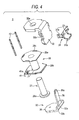
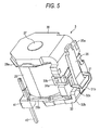
- the coil block 3 is obtained by winding a coil 29 onto a core 27 through a spool 28 as shown in Figs. 4 and 5.
- a yoke 30 is fixed to the upper end of the core 27.
- a flange-like lower end of the core 27 operates as an attraction surface 27a.
- the yoke 30 is constituted by a substantially L-shaped magnetic material and has an opening 30a into which the core 27 is fitted and fixed by inserting therein, at the center of one of its ends.
- An anchor acceptance portion 30b for fitting a hinge spring 31 is formed at a side edge of the other end of the yoke 30.
- the other end of the yoke 30 operates as a support point for rotation.
- a substantially L-shaped moving iron plate 32 is supported under the state where it is held by the hinge spring 31 in such a fashion that a bent portion 33 can freely rock.
- the hinge spring 31 includes an anchor portion 31a anchored to the anchor acceptance portion 30b of the yoke 30 described above and a rectangular pressure contact portion 31b into which the reduced width portion 35 of the moving iron plate 32 is fitted and which comes into pressure contact with the bent portion 33.
- the rectangular pressure contact portion 31b comes into pressure contact with a step portion 32a and a curved surface 32b of the bent portion 33 of the moving iron plate 32 and urges the moving iron plate 32 counter-clockwise in Fig. 2, that is, in a direction in which the attracted portion 34b comes away from the attraction surface 27a of the core 27.
- the card 100 is interposed between the anchor portion 35a of the moving iron plate 32 and the card acceptance portion 24 of the moving contact plate 20.
- the card 100 has at one of its ends an anchor holding portion 36 to which the anchor portion 35a of the moving iron plate 32 is anchored and at its other end a push-in portion 37 into which the card acceptance portion 24 is pushed.
- the anchor holding portion 36 has a contact plate 38 that comes into contact with the anchor portion 35a of the moving iron plate 32, and a flexible holding plate 39 that flexibly holds the anchor portion 35a from both sides.
- a clearance is defined between the contact plate 38 and the flexible holding plate 39.
- the push-in portion 37 has a reduced thickness portion 37a and guide plates 37b, 37b that are positioned on both sides of the reduced thickness portion 37a and are supported by the card acceptance portions 24b on the lower side.
- the distal end of the reduced thickness portion 37a is preferably shaped into a taper surface or a curve surface so that the reduced thickness portion 37a can come into surface contact with the card acceptance portions 24a and 24b of the moving contact plate 20.
- a card reinforcement rib 40 having a substantial E shape when viewed on a plane reinforces the reduced thickness portion 37a.
- Upper and lower card acceptance portions 24a and 24b of the moving contact plate 20 come into contact with the upper and lower surface edge portions of the reduced thickness portion 37a, respectively.
- the card reinforcement rib 40 not only reinforces the reduced thickness portion 37a but also allows a resin to smoothly flow when the card 100 is molded, and prevents the occurrence of problems such as short shot.
- the guide plates 37b and 37b guide from both sides the card acceptance portion 24a on the upper side.
- the spool 28 has a cylindrical shape and the core 27 is inserted through the spool 28.
- the spool 28 has flanges 28a and 28b at its both ends. Protuberances 28c are formed at three positions on the periphery of the upper flange 28a and guide the yoke 30.
- Increased thickness portions 41 are formed on both sides of the lower flange 28b. Each increased thickness portion 41 has a terminal hole 41a into which the coil terminal 42 is pushed.
- a ring-like recess 43 is formed around the terminal hole 41a on the bottom surface side.
- Each increased thickness portion 41 is pushed into each push-in acceptance portion 17 of the base 1 when the coil block 3 is fitted to the base 1, stores a sealant entering from the through-hole 15 in its ring-like recess 43 and prevents further inflow.
- the ring-like recess 43 is formed in such a fashion that its depth progressively increases towards the outer diameter side. In this way, the length of the terminal hole 41a can be sufficiently secured, the push-in margin of the coil terminal 42 can be secured and the push-in state can be stabilized.
- the ring-like recess 43 may be constituted in such a fashion that it is deeper or broader on the side opposite to the region in which the moving iron plate 32 rotates. According to this construction, the fluidization direction of the inflowing sealant can be directed to the side opposite to the region described above. Even when the sealant fluidizes beyond the ring-like recess 43, for example, adverse influences are not exerted on the operation of the moving iron plate 32.
- the increased thickness portion 41 preferably has a construction capable of coming into surface contact on its slope with the partition wall 12.
- a slope that progressively inclines inwards towards the bottom surface is formed in the increased thickness portion 41.
- a slope is formed on the partition wall 12 in such a fashion as to gradually expand the open area of the push-in acceptance portion 17.
- the coil 29 is wound on a drum portion of the spool 28 and both of its ends are wound on the coil terminal 42, respectively.
- the case 4 has substantially a box shape the lower surface of which is open.
- the case 4 covers constituent components.
- a gas vent hole 44 is formed at a corner of the upper surface to emit the gas resulting from the seal work to the outside.
- the gas vent hole 44 is thermally sealed when the electromagnetic relay is completed.
- First and second protuberance portions 45 and 46 protruding inward are formed at a corner and a substantially center portion of the ceiling surface of the base 1 as shown in Fig. 2, respectively.
- the first protuberance portion 45 guides the yoke 30 and the second protuberance portion 46 restricts the moving range of the card 100.
- the coil block 3 is formed in a separate step.
- the coil 29 is wound on the core 27 through the spool 28 as shown in Fig. 4 and both ends of the coil 29 are wound on the coil terminals 42 pushed into and fixed to the increased thickness portion 41, respectively.
- One of the ends of the yoke 30 is fixed to the upper end of the core 27 and the moving iron plate 32 is arranged at the other end of the yoke 30 in such a fashion as to be capable of rocking.
- the moving iron plate 32 is fitted to the yoke 30 through the hinge spring 31 and is urged to come away from the attraction surface 27a of the core 27.
- the coil block 3 shown in Fig. 5 is thus completed.
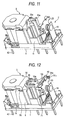
- the moving contact plate 20 and the first and second fixed contact plates 19 and 21 are pushed into and fixed to the base 1 as shown in Fig. 9 and the completed coil block 3 is assembled to the base 1 as shown in Figs. 10 and 11.
- the coil block 3 is fixed as the increased thickness portion 41 is pushed into the push-in acceptance portion 17 and both side portions 9 of the yoke 30 are pushed into the inner surface groove portion 9a.
- a space is defined under this state between the base 1 and the coil block 3 and a rotation space of the moving iron plate 32 can be secured.
- the escape recess 13 formed in the base 1 restricts the height of the electromagnetic relay.
- Each contact plate is pushed into and fixed to the base 1 in the sequence of the first fixed contact plate 19, the moving contact plate 20 and the second fixed contact plate 21.
- the second fixed contact plate 21 When the second fixed contact plate 21 is first pushed in, its bent portion prevents the push-in operation of the moving contact plate 20. Therefore, the moving contact plate 20 is first pushed in and then the second fixed contact plate 21 is pushed in and fixed. In this case, the escape portion 25 prevents the interference of the second fixed contact 26 though the card acceptance portion 24 is formed at the upper end of the moving contact plate 20.
- the anchor holding portion 36 of the card 100 is anchored to the anchor portion 35a of the moving iron plate 32 as shown in Fig. 12.
- the flexible holding plate 39 undergoes elastic deformation and then returns to its original shape.
- the flexible holding plate 39 and the contact plate 38 hold the anchor portion 35a.
- the reduced thickness portion 37a of the card 100 is positioned between the upper and lower card acceptance portions 24 formed at the upper end of the moving contact plate 20. As shown in Figs. 14 and 15, the card acceptance portions 24 prevent fall-off of the card 100 in the vertical direction and the guide plate 37b formed on the card 100 prevents a positioning error of the card 100 in the transverse direction.
- the case 4 is fitted to the base 1 as shown in Fig. 13 to cover the constituent components.
- the base 1 is turned upside down so that its bottom surface faces upward, and the terminal holes and the fitting portion between the base 1, the case 4, and so forth, are sealed with the sealant by use of a nozzle, or the like.
- the sealant enters the inside due to capillary.
- the sealant entering from the clearance between each terminal portion 19b, 19c, 20b, 20c, 21b, 21c of each contact plate 19, 20, 21 and the terminal hole is far from the region in which the contacts are opened and closed, and improves the fixing strength of the contact plates to the base 1.
- the sealant entering from the clearance between the coil terminal 42 and the through-hole 15 is stored in the ring-like recess 43 formed in the increased thickness portion 41 of the coil block 3 and its further invasion is checked. Even when the sealant enters beyond the ring-like recess portion 43, the partition wall 12 prevents the sealant from reaching the driving region of the moving iron plate 32. Therefore, even when the driving region of the moving iron plate 32 is positioned in the proximity of the region that the sealant enters, the problem due to adhesion, etc does not occur.
- the electromagnetic relay is completed in the manner described above.
- the gas vent hole 44 formed in the case 4 may well be used while left open or under the sealed state after it is thermally sealed depending on the environment of use. Even when impact force acts on the internal constituent components due to fall, or the like, no problem occurs because each component is firmly fixed to the base 1.
- the card 100 in particular, has the simple construction in which the moving iron plate 32 and the moving contact plate 20 are merely interconnected. One of the ends of the card is interconnected to the moving iron plate 32 through the anchor holding portion 36 and the other end guides the reduced thickness portion 37a of the push-in portion 37 within the range in which the moving contact plate 20 can undergo deformation.
- the upper end protuberance portion 10a formed on the insulating wall 5 of the base 1 is positioned between the contact plate 38 and the flexible holding plate 39 constituting the anchor holding portion 36 and the second protuberance portion 46 formed on the case 4 is positioned above the card 100. Therefore, even when any impact force operates, the card 100 does not fall off.
- the moving iron plate 32 rotates counter-clockwise in Fig. 2 due to the urging force of the hinge spring 31 with the rotation support point at the distal end of the yoke 30 being the center.
- the moving contact plate 20 is under the erected state due to its own flexible force and keeps the moving contact 23 under the closed state relative to the second fixed contact 26.
- the fixed contact plates 19 and 20 are disposed on both sides of the moving contact plate 20, but they may be disposed on only one side. In other words, it is possible to employ a construction in which only the second fixed contact plate 21 is not disposed but the rest of the constituent components are as such used as shown in Fig. 16.
- the guide plate 37b of the card 100 is disposed separately from the card reinforcement ribs 40.
- the card reinforcement ribs 40 operate also as the guide plate 37b.
- the card reinforcement ribs 40 positioned on both sides guide both sides 9 of the upper card acceptance portion 24.
- At least one each card acceptance portion 24 of the moving contact plate 20 may well exist at the upper and lower positions.
- the card acceptance portion 24 may well be formed at the center.
- the recess is formed in the increased thickness portion of the spool in the invention. Therefore, the sealant entering from the through-hole of the base does not enter the inside beyond the recess, and does not exert adverse influences on the operation portion even in the construction in which the moving iron plate is operated inside the space defined between the coil block and the base.
Landscapes
- Physics & Mathematics (AREA)
- Electromagnetism (AREA)
- Electromagnets (AREA)
Applications Claiming Priority (2)
| Application Number | Priority Date | Filing Date | Title |
|---|---|---|---|
| JP2002325242A JP4131160B2 (ja) | 2002-11-08 | 2002-11-08 | 電磁継電器 |
| JP2002325242 | 2002-11-08 |
Publications (2)
| Publication Number | Publication Date |
|---|---|
| EP1418604A1 true EP1418604A1 (fr) | 2004-05-12 |
| EP1418604B1 EP1418604B1 (fr) | 2006-05-03 |
Family
ID=32105495
Family Applications (1)
| Application Number | Title | Priority Date | Filing Date |
|---|---|---|---|
| EP03024555A Expired - Lifetime EP1418604B1 (fr) | 2002-11-08 | 2003-10-27 | Relais électromagnétique |
Country Status (6)
| Country | Link |
|---|---|
| US (1) | US6903639B2 (fr) |
| EP (1) | EP1418604B1 (fr) |
| JP (1) | JP4131160B2 (fr) |
| CN (1) | CN1294605C (fr) |
| DE (1) | DE60304969T8 (fr) |
| ES (1) | ES2258692T3 (fr) |
Cited By (2)
| Publication number | Priority date | Publication date | Assignee | Title |
|---|---|---|---|---|
| EP2466608A3 (fr) * | 2010-12-16 | 2013-07-31 | Tyco Electronics Austria GmbH | Relais doté d'un ressort de contact amélioré |
| EP3770940A4 (fr) * | 2018-03-27 | 2021-12-29 | Omron Corporation | Relais |
Families Citing this family (18)
| Publication number | Priority date | Publication date | Assignee | Title |
|---|---|---|---|---|
| ITPC20050004U1 (it) * | 2005-03-10 | 2006-09-11 | Electrica Srl | Rele' voltmetrico con aggancio migliorato dei terminali |
| DE102006021203B3 (de) * | 2006-05-06 | 2008-01-17 | Tyco Electronics Austria Gmbh | Elektrisches Relais |
| DE102006036613B3 (de) * | 2006-08-04 | 2008-04-10 | Tyco Electronics Austria Gmbh | Relais mit einer Konkaktanordnung aus Kontaktfedern |
| JP4952324B2 (ja) * | 2007-03-22 | 2012-06-13 | オムロン株式会社 | 電磁継電器 |
| JP2014139898A (ja) * | 2013-01-21 | 2014-07-31 | Fujitsu Component Ltd | 電磁継電器 |
| JP2015035403A (ja) * | 2013-08-09 | 2015-02-19 | オムロン株式会社 | 接点機構およびこれを用いた電磁継電器 |
| JP6263904B2 (ja) * | 2013-08-23 | 2018-01-24 | オムロン株式会社 | 電磁石装置およびこれを用いた電磁継電器 |
| US9159514B2 (en) * | 2013-11-18 | 2015-10-13 | Tyco Electronics Corporation | Relay connector assembly for a relay system |
| JP6422249B2 (ja) * | 2014-07-03 | 2018-11-14 | 富士通コンポーネント株式会社 | 電磁継電器 |
| WO2016013485A1 (fr) * | 2014-07-23 | 2016-01-28 | 富士通コンポーネント株式会社 | Relais électromagnétique |
| JP6433706B2 (ja) * | 2014-07-28 | 2018-12-05 | 富士通コンポーネント株式会社 | 電磁継電器及びコイル端子 |
| CN104752100B (zh) * | 2015-01-30 | 2017-03-29 | 厦门宏发汽车电子有限公司 | 一种车载pcb电磁继电器 |
| CN105551889B (zh) * | 2015-12-03 | 2019-02-19 | 厦门宏发电力电器有限公司 | 一种磁保持继电器及其装配方法 |
| JP6664978B2 (ja) * | 2016-01-29 | 2020-03-13 | 富士通コンポーネント株式会社 | 電磁継電器 |
| JP6787182B2 (ja) * | 2017-02-28 | 2020-11-18 | オムロン株式会社 | 電子機器のシール構造、シール構造を備えた電子機器、および、電子機器の製造方法 |
| JP6973200B2 (ja) * | 2018-03-13 | 2021-11-24 | オムロン株式会社 | 接点開閉装置 |
| JP7003787B2 (ja) | 2018-03-27 | 2022-01-21 | オムロン株式会社 | リレー |
| JP2025105260A (ja) * | 2023-12-28 | 2025-07-10 | Fclコンポーネント株式会社 | 電磁継電器 |
Citations (4)
| Publication number | Priority date | Publication date | Assignee | Title |
|---|---|---|---|---|
| US4246437A (en) * | 1977-12-02 | 1981-01-20 | International Standard Electric Corporation | Sealing apertures through which electrical terminals protrude |
| JPH05242784A (ja) * | 1992-02-28 | 1993-09-21 | Matsushita Electric Works Ltd | 電磁リレー |
| JPH0896683A (ja) * | 1994-09-27 | 1996-04-12 | Matsushita Electric Works Ltd | 電磁リレー |
| EP1246214A2 (fr) * | 2001-03-26 | 2002-10-02 | Takamisawa Electric Co., Ltd. | Relais électromagnétique |
Family Cites Families (10)
| Publication number | Priority date | Publication date | Assignee | Title |
|---|---|---|---|---|
| JPS636647U (fr) * | 1986-06-28 | 1988-01-18 | ||
| JPS63149039U (fr) * | 1987-03-20 | 1988-09-30 | ||
| JPH0198447U (fr) * | 1987-12-23 | 1989-06-30 | ||
| US5021760A (en) * | 1989-10-03 | 1991-06-04 | Clum Manufacturing Company, Inc. | Solenoid switch contact and mounting assembly |
| JPH067398U (ja) * | 1992-06-26 | 1994-01-28 | 京セラ株式会社 | 発音体 |
| JP3675867B2 (ja) * | 1995-01-13 | 2005-07-27 | 東光株式会社 | コイル装置 |
| DE69612771T2 (de) * | 1995-02-15 | 2002-04-18 | Matsushita Electric Works, Ltd. | Elektromagnetisches Relais |
| JPH10162710A (ja) * | 1996-11-28 | 1998-06-19 | Matsushita Electric Works Ltd | 電磁リレー及びその製造方法 |
| JP3948091B2 (ja) * | 1998-01-27 | 2007-07-25 | 松下電工株式会社 | 電磁継電器 |
| JP4096029B2 (ja) * | 2002-11-06 | 2008-06-04 | Smc株式会社 | 電磁弁 |
-
2002
- 2002-11-08 JP JP2002325242A patent/JP4131160B2/ja not_active Expired - Lifetime
-
2003
- 2003-10-27 DE DE60304969T patent/DE60304969T8/de active Active
- 2003-10-27 ES ES03024555T patent/ES2258692T3/es not_active Expired - Lifetime
- 2003-10-27 EP EP03024555A patent/EP1418604B1/fr not_active Expired - Lifetime
- 2003-10-28 US US10/695,406 patent/US6903639B2/en not_active Expired - Lifetime
- 2003-11-10 CN CNB2003101156413A patent/CN1294605C/zh not_active Expired - Fee Related
Patent Citations (4)
| Publication number | Priority date | Publication date | Assignee | Title |
|---|---|---|---|---|
| US4246437A (en) * | 1977-12-02 | 1981-01-20 | International Standard Electric Corporation | Sealing apertures through which electrical terminals protrude |
| JPH05242784A (ja) * | 1992-02-28 | 1993-09-21 | Matsushita Electric Works Ltd | 電磁リレー |
| JPH0896683A (ja) * | 1994-09-27 | 1996-04-12 | Matsushita Electric Works Ltd | 電磁リレー |
| EP1246214A2 (fr) * | 2001-03-26 | 2002-10-02 | Takamisawa Electric Co., Ltd. | Relais électromagnétique |
Non-Patent Citations (2)
| Title |
|---|
| PATENT ABSTRACTS OF JAPAN vol. 017, no. 698 (E - 1481) 20 December 1993 (1993-12-20) * |
| PATENT ABSTRACTS OF JAPAN vol. 1996, no. 08 30 August 1996 (1996-08-30) * |
Cited By (2)
| Publication number | Priority date | Publication date | Assignee | Title |
|---|---|---|---|---|
| EP2466608A3 (fr) * | 2010-12-16 | 2013-07-31 | Tyco Electronics Austria GmbH | Relais doté d'un ressort de contact amélioré |
| EP3770940A4 (fr) * | 2018-03-27 | 2021-12-29 | Omron Corporation | Relais |
Also Published As
| Publication number | Publication date |
|---|---|
| US6903639B2 (en) | 2005-06-07 |
| CN1294605C (zh) | 2007-01-10 |
| DE60304969D1 (de) | 2006-06-08 |
| CN1499556A (zh) | 2004-05-26 |
| JP2004158382A (ja) | 2004-06-03 |
| JP4131160B2 (ja) | 2008-08-13 |
| DE60304969T8 (de) | 2007-05-03 |
| EP1418604B1 (fr) | 2006-05-03 |
| US20040130419A1 (en) | 2004-07-08 |
| ES2258692T3 (es) | 2006-09-01 |
| DE60304969T2 (de) | 2007-01-04 |
Similar Documents
| Publication | Publication Date | Title |
|---|---|---|
| EP1420429B1 (fr) | Relais électromagnétique | |
| EP1420428B1 (fr) | Relais électromagnétique | |
| EP1418604B1 (fr) | Relais électromagnétique | |
| US7750769B2 (en) | Electromagnetic relay | |
| US7956710B2 (en) | Electromagnetic relay | |
| JP4952325B2 (ja) | 電磁継電器 | |
| KR20140102126A (ko) | 전자 계전기 | |
| JP2003346624A (ja) | 高周波リレー | |
| JP2004158381A (ja) | 電磁継電器 | |
| JP4039122B2 (ja) | 高周波リレー | |
| JP3932700B2 (ja) | 電磁継電器 | |
| JP3932716B2 (ja) | 電磁継電器 | |
| JP4172205B2 (ja) | 高周波リレー | |
| JP4250912B2 (ja) | 高周波リレー | |
| CN120236936A (zh) | 电磁继电器 |
Legal Events
| Date | Code | Title | Description |
|---|---|---|---|
| PUAI | Public reference made under article 153(3) epc to a published international application that has entered the european phase |
Free format text: ORIGINAL CODE: 0009012 |
|
| AK | Designated contracting states |
Kind code of ref document: A1 Designated state(s): AT BE BG CH CY CZ DE DK EE ES FI FR GB GR HU IE IT LI LU MC NL PT RO SE SI SK TR |
|
| AX | Request for extension of the european patent |
Extension state: AL LT LV MK |
|
| 17P | Request for examination filed |
Effective date: 20040628 |
|
| AKX | Designation fees paid |
Designated state(s): DE ES FR GB IT |
|
| GRAP | Despatch of communication of intention to grant a patent |
Free format text: ORIGINAL CODE: EPIDOSNIGR1 |
|
| GRAS | Grant fee paid |
Free format text: ORIGINAL CODE: EPIDOSNIGR3 |
|
| GRAA | (expected) grant |
Free format text: ORIGINAL CODE: 0009210 |
|
| AK | Designated contracting states |
Kind code of ref document: B1 Designated state(s): DE ES FR GB IT |
|
| PG25 | Lapsed in a contracting state [announced via postgrant information from national office to epo] |
Ref country code: IT Free format text: LAPSE BECAUSE OF FAILURE TO SUBMIT A TRANSLATION OF THE DESCRIPTION OR TO PAY THE FEE WITHIN THE PRESCRIBED TIME-LIMIT;WARNING: LAPSES OF ITALIAN PATENTS WITH EFFECTIVE DATE BEFORE 2007 MAY HAVE OCCURRED AT ANY TIME BEFORE 2007. THE CORRECT EFFECTIVE DATE MAY BE DIFFERENT FROM THE ONE RECORDED. Effective date: 20060503 |
|
| REG | Reference to a national code |
Ref country code: GB Ref legal event code: FG4D |
|
| REF | Corresponds to: |
Ref document number: 60304969 Country of ref document: DE Date of ref document: 20060608 Kind code of ref document: P |
|
| REG | Reference to a national code |
Ref country code: ES Ref legal event code: FG2A Ref document number: 2258692 Country of ref document: ES Kind code of ref document: T3 |
|
| ET | Fr: translation filed | ||
| PLBE | No opposition filed within time limit |
Free format text: ORIGINAL CODE: 0009261 |
|
| STAA | Information on the status of an ep patent application or granted ep patent |
Free format text: STATUS: NO OPPOSITION FILED WITHIN TIME LIMIT |
|
| 26N | No opposition filed |
Effective date: 20070206 |
|
| REG | Reference to a national code |
Ref country code: DE Ref legal event code: R082 Ref document number: 60304969 Country of ref document: DE Representative=s name: KILIAN KILIAN & PARTNER, DE Ref country code: DE Ref legal event code: R082 Ref document number: 60304969 Country of ref document: DE Representative=s name: KILIAN KILIAN & PARTNER MBB PATENTANWAELTE, DE |
|
| PGFP | Annual fee paid to national office [announced via postgrant information from national office to epo] |
Ref country code: FR Payment date: 20121022 Year of fee payment: 10 |
|
| PGFP | Annual fee paid to national office [announced via postgrant information from national office to epo] |
Ref country code: IT Payment date: 20121024 Year of fee payment: 10 Ref country code: ES Payment date: 20121030 Year of fee payment: 10 |
|
| REG | Reference to a national code |
Ref country code: FR Ref legal event code: ST Effective date: 20140630 |
|
| PG25 | Lapsed in a contracting state [announced via postgrant information from national office to epo] |
Ref country code: FR Free format text: LAPSE BECAUSE OF NON-PAYMENT OF DUE FEES Effective date: 20131031 Ref country code: IT Free format text: LAPSE BECAUSE OF NON-PAYMENT OF DUE FEES Effective date: 20131027 |
|
| REG | Reference to a national code |
Ref country code: ES Ref legal event code: FD2A Effective date: 20141107 |
|
| PG25 | Lapsed in a contracting state [announced via postgrant information from national office to epo] |
Ref country code: ES Free format text: LAPSE BECAUSE OF NON-PAYMENT OF DUE FEES Effective date: 20131028 |
|
| PGFP | Annual fee paid to national office [announced via postgrant information from national office to epo] |
Ref country code: GB Payment date: 20181024 Year of fee payment: 16 |
|
| PGFP | Annual fee paid to national office [announced via postgrant information from national office to epo] |
Ref country code: DE Payment date: 20191015 Year of fee payment: 17 |
|
| GBPC | Gb: european patent ceased through non-payment of renewal fee |
Effective date: 20191027 |
|
| PG25 | Lapsed in a contracting state [announced via postgrant information from national office to epo] |
Ref country code: GB Free format text: LAPSE BECAUSE OF NON-PAYMENT OF DUE FEES Effective date: 20191027 |
|
| REG | Reference to a national code |
Ref country code: DE Ref legal event code: R119 Ref document number: 60304969 Country of ref document: DE |
|
| PG25 | Lapsed in a contracting state [announced via postgrant information from national office to epo] |
Ref country code: DE Free format text: LAPSE BECAUSE OF NON-PAYMENT OF DUE FEES Effective date: 20210501 |