EP1418691A2 - Réseau optique passif utilisant une lumière multilongueurs d'ondes générée en boucle au central - Google Patents
Réseau optique passif utilisant une lumière multilongueurs d'ondes générée en boucle au central Download PDFInfo
- Publication number
- EP1418691A2 EP1418691A2 EP03025678A EP03025678A EP1418691A2 EP 1418691 A2 EP1418691 A2 EP 1418691A2 EP 03025678 A EP03025678 A EP 03025678A EP 03025678 A EP03025678 A EP 03025678A EP 1418691 A2 EP1418691 A2 EP 1418691A2
- Authority
- EP
- European Patent Office
- Prior art keywords
- port
- channels
- inputted
- multiplexing
- ports
- Prior art date
- Legal status (The legal status is an assumption and is not a legal conclusion. Google has not performed a legal analysis and makes no representation as to the accuracy of the status listed.)
- Withdrawn
Links
Images


Classifications
-
- H—ELECTRICITY
- H04—ELECTRIC COMMUNICATION TECHNIQUE
- H04L—TRANSMISSION OF DIGITAL INFORMATION, e.g. TELEGRAPHIC COMMUNICATION
- H04L12/00—Data switching networks
-
- H—ELECTRICITY
- H04—ELECTRIC COMMUNICATION TECHNIQUE
- H04B—TRANSMISSION
- H04B10/00—Transmission systems employing electromagnetic waves other than radio-waves, e.g. infrared, visible or ultraviolet light, or employing corpuscular radiation, e.g. quantum communication
- H04B10/25—Arrangements specific to fibre transmission
- H04B10/2587—Arrangements specific to fibre transmission using a single light source for multiple stations
-
- H—ELECTRICITY
- H04—ELECTRIC COMMUNICATION TECHNIQUE
- H04J—MULTIPLEX COMMUNICATION
- H04J14/00—Optical multiplex systems
- H04J14/02—Wavelength-division multiplex systems
- H04J14/0226—Fixed carrier allocation, e.g. according to service
-
- H—ELECTRICITY
- H04—ELECTRIC COMMUNICATION TECHNIQUE
- H04J—MULTIPLEX COMMUNICATION
- H04J14/00—Optical multiplex systems
- H04J14/02—Wavelength-division multiplex systems
- H04J14/0227—Operation, administration, maintenance or provisioning [OAMP] of WDM networks, e.g. media access, routing or wavelength allocation
- H04J14/0241—Wavelength allocation for communications one-to-one, e.g. unicasting wavelengths
- H04J14/0242—Wavelength allocation for communications one-to-one, e.g. unicasting wavelengths in WDM-PON
- H04J14/0245—Wavelength allocation for communications one-to-one, e.g. unicasting wavelengths in WDM-PON for downstream transmission, e.g. optical line terminal [OLT] to ONU
- H04J14/0246—Wavelength allocation for communications one-to-one, e.g. unicasting wavelengths in WDM-PON for downstream transmission, e.g. optical line terminal [OLT] to ONU using one wavelength per ONU
-
- H—ELECTRICITY
- H04—ELECTRIC COMMUNICATION TECHNIQUE
- H04J—MULTIPLEX COMMUNICATION
- H04J14/00—Optical multiplex systems
- H04J14/02—Wavelength-division multiplex systems
- H04J14/0227—Operation, administration, maintenance or provisioning [OAMP] of WDM networks, e.g. media access, routing or wavelength allocation
- H04J14/0241—Wavelength allocation for communications one-to-one, e.g. unicasting wavelengths
- H04J14/0242—Wavelength allocation for communications one-to-one, e.g. unicasting wavelengths in WDM-PON
- H04J14/0249—Wavelength allocation for communications one-to-one, e.g. unicasting wavelengths in WDM-PON for upstream transmission, e.g. ONU-to-OLT or ONU-to-ONU
- H04J14/025—Wavelength allocation for communications one-to-one, e.g. unicasting wavelengths in WDM-PON for upstream transmission, e.g. ONU-to-OLT or ONU-to-ONU using one wavelength per ONU, e.g. for transmissions from-ONU-to-OLT or from-ONU-to-ONU
-
- H—ELECTRICITY
- H04—ELECTRIC COMMUNICATION TECHNIQUE
- H04Q—SELECTING
- H04Q11/00—Selecting arrangements for multiplex systems
- H04Q11/0001—Selecting arrangements for multiplex systems using optical switching
- H04Q11/0062—Network aspects
- H04Q11/0067—Provisions for optical access or distribution networks, e.g. Gigabit Ethernet Passive Optical Network (GE-PON), ATM-based Passive Optical Network (A-PON), PON-Ring
-
- H—ELECTRICITY
- H04—ELECTRIC COMMUNICATION TECHNIQUE
- H04J—MULTIPLEX COMMUNICATION
- H04J14/00—Optical multiplex systems
- H04J14/02—Wavelength-division multiplex systems
- H04J14/0227—Operation, administration, maintenance or provisioning [OAMP] of WDM networks, e.g. media access, routing or wavelength allocation
- H04J14/0241—Wavelength allocation for communications one-to-one, e.g. unicasting wavelengths
- H04J14/0242—Wavelength allocation for communications one-to-one, e.g. unicasting wavelengths in WDM-PON
- H04J2014/0253—Allocation of downstream wavelengths for upstream transmission
-
- H—ELECTRICITY
- H04—ELECTRIC COMMUNICATION TECHNIQUE
- H04Q—SELECTING
- H04Q11/00—Selecting arrangements for multiplex systems
- H04Q11/0001—Selecting arrangements for multiplex systems using optical switching
- H04Q11/0005—Switch and router aspects
- H04Q2011/0007—Construction
- H04Q2011/0016—Construction using wavelength multiplexing or demultiplexing
Definitions
- the present invention relates to an optical communication system, and more particularly to a wavelength division multiplexing passive optical network.
- a wavelength division multiplexing (WDM) passive optical network distributes, optical signals downstream from a central office to each subscriber.
- the network uses at a remote node between the central office and the subscriber a passive element instead of an active element, such as an amplifier, a transmitter and so forth.
- an active element such as an amplifier, a transmitter and so forth.
- upstream optical signals together with data for the subscriber are sent through the passive element to the central office.
- both the central office and the remote node require an apparatus for multiplexing and/or demultiplexing upstream and downstream optical signals
- both the central office and the subscriber require a transmitter and a receiver.
- Fig. 1 illustrates construction of a conventional WDM passive optical network.
- This WDM passive optical network includes a central office 110 and a subscriber-side apparatus 130,140 connected with the central office 110 through optical fiber links 120, 125, respectively.
- the subscriber-side apparatus includes a remote node 130 and a plurality of subscribers 140 connected with the remote node 130.
- the central office 110 includes a plurality of optical transmitters 111, a plurality of optical receivers 114, a multiplexer 112 and a demultiplexer 113.
- Each of the optical transmitters 111 outputs channels, which are modulated with the corresponding data signals and have different wavelengths.
- the optical transmitter 111 for example, makes much use of a distributed feedback laser diode (DFB LD) appropriate to downstream optical signals for transmission of high capacity data.
- DFB LD distributed feedback laser diode
- the multiplexer 112 multiplexes channels inputted from the transmitters 111 into downstream optical signals, and then transmits the multiplexed downstream optical signals through the optical fiber link 120.
- the multiplexer 112 may make use of a passive element such as a 1xN AWG, for example.
- the demultiplexer 113 demultiplexes upstream optical signals received through the optical fiber link 125 into a plurality of channels, and then outputs the demultiplexed channels.
- the demultiplexer 113 may also make use of a passive element such as a 1xN AWG.
- the optical receivers 114 convert each of the channels inputted from the demultiplexer 113 into an electrical signal.
- the optical receiver 114 makes use of a photodiode, for example.
- the subscriber-side apparatus 130, 140 includes a demultiplexer 131, a multiplexer 132, a plurality of optical transmitters 142 and a plurality of optical receivers 141.
- the demultiplexer 131 demultiplexes downstream optical signals received through the optical fiber link 120 into a plurality of channels, and then outputs the results.
- the optical receivers 141 convert each of the channels inputted from the demultiplexer 131 into an electrical signal.
- the optical transmitters 142 each output a plurality of channels, which are modulated with the corresponding data signals and have different wavelengths.
- the optical transmitter 142 makes much use of either a spectrum-sliced light source appropriate to upstream optical signals for transmission of relatively low capacity data or a light source for generating only a single mode by locking a multi-mode laser diode.
- the multiplexer 132 multiplexes a plurality of channels inputted from the transmitters 142 into upstream optical signals, and then transmits the multiplexed upstream optical signals through the optical fiber link 125.
- the conventional WDM passive optical network has a problem in that transmission of a high volume of optical signals caused by a sharp growth in volume of the upstream optical signals, when either the spectrum-sliced light source or the light source for generating only a single mode by locking a multi-mode laser diode is used as a light source for transmitting upstream optical signals, makes operation of the network impossible or causes a transmission error rate to increase rapidly.
- costs for constructing the subscriber-side apparatus are increased when a single mode laser diode such as the DFB LD is used as a light source for transmitting upstream optical signals.
- the present invention is directed to solving the above-mentioned problems occurring in the prior art.
- the present invention provides a wavelength division multiplexing (WDM) passive optical network capable not only of efficiently containing upstream optical signals in spite of an increase in transmission capacity of the upstream optical signals, but also of saving the costs for constructing the subscriber-side apparatus.
- WDM wavelength division multiplexing
- the present invention provides a passive optical network including a central office and a subscriber-side apparatus connected with the central office through an optical fiber link, in which the subscriber-side apparatus performs communication with the central office based on wavelength-division-multiplexed optical signals
- the central office comprising: a routing section, provided with first to fourth multiplexing ports, for demultiplexing multi-wavelength light inputted through the fourth multiplexing port into a plurality of channels, for amplifying and multiplexing each of these demultiplexed channels, for outputting the results through the first multiplexing port, for demultiplexing and outputting upstream optical signals inputted through the third multiplexing port, for multiplexing channels for downstream optical signals and for outputting the multiplexed channels through the second multiplexing port; a splitting section, provided with first to third splitting ports and arranged on a loop optical waveguide connecting the first and fourth multiplexing port with each other, for causing some of multi-wavelength light inputted into the first splitting port to be outputted through the second splitting
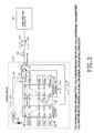
- Fig. 2 illustrates construction of a wavelength division multiplexing (WDM) passive optical network according to the present invention.
- the passive optical network includes a central office 200 and a subscriber-side apparatus 310, in which the subscriber-side apparatus 310 is connected with the central office 200 through an optical fiber link 300 and performs communication with the central office 200 based on wavelength-division-multiplexed optical signals.
- WDM wavelength division multiplexing
- the central office 200 transmits downstream optical signals, which are modulated with multi-wavelength light and data signals, to the subscriber-side apparatus 310, and receives upstream optical signals from the subscriber-side apparatus 310.
- the subscriber-side apparatus 310 receives multi-wavelength light and the downstream optical signals from the central office 200, demultiplexes the multi-wavelength light into a plurality of channels, modulates each of the channels into data signals, multiplexes the modulated channels into upstream optical signals, and transmits the multiplexed upstream optical signals to the central office 200.
- the central office 200 includes a routing section 210, a splitting section 250, a circulator 260, a combining section 270, an optical transmitting section 280, an optical receiving section 290, an isolator 230, and an optical band pass filter (OBPF) 240.
- OBPF optical band pass filter
- the routing section 210 includes first and second wavelength routers 211 and 212, and a plurality of optical amplifiers 213.
- the second wavelength router 212 comprises third and fourth multiplexing ports LN and R1, and third and fourth demultiplexing multi-ports L 1 to L N-1 and R 2 to R N .
- the second wavelength router 212 demultiplexes multi-wavelength light, inputted from the fourth multiplexing port R 1 , into a plurality of channels, and then outputs the demultiplexed channels through the third demultiplexing multi-ports L 1 to L N-1 . Further, the second wavelength router 212 demultiplexes upstream optical signals, inputted from the third multiplexing port L N , into a plurality of channels, and then outputs the demultiplexed channels through the fourth demultiplexing multi-ports R 2 to R N .
- the second wavelength router 212 may, for example, make use of an element that has a periodicity like an NxN arrayed waveguide grating and performs multiplexing and demultiplexing in both directions.
- the optical amplifiers 213 are connected with the corresponding third demultiplexing multi-ports L 1 to L N-1 and cause channels inputted from these ports to be amplified and outputted. Further, the optical amplifiers 213 functions as a light source for multi-wavelength light. Amplified spontaneous emission (ASE) generated from each optical amplifier 213 turns to multi-wavelength light after it is sequentially subjected to filtering, amplification, and so forth, and then is transmitted to the subscriber-side apparatus 310 as multi-wavelength light.
- Each of the optical amplifiers 213 includes an erbium doped fiber (EDF) and a pumping light source for supplying pumping light by means of the EDF.
- EDF erbium doped fiber
- the first wavelength router 211 comprises first and second multiplexing ports L1 and RN, and first and second demultiplexing multi-ports L 2 to L N and R 1 to R N-1 .
- the first wavelength router 211 multiplexes the amplified channels inputted into the second demultiplexing multi-ports R 1 to R N-1 , and then outputs the multiplexed channels through the first multiplexing port L 1 .
- the first wavelength router 211 multiplexes channels inputted into the first demultiplexing multi-ports L 2 to L N , and then outputs the multiplexed channels through the second multiplexing port R N .
- the first wavelength router 211 may, for example, make use of an element that has a periodicity like an NxN arrayed waveguide grating and performs multiplexing and demultiplexing in both directions.
- Both the first multiplexing port L 1 of the first wavelength router 211 and the fourth multiplexing port R 1 of the second wavelength router 212 are connected with each other by an optical waveguide, thus forming a loop optical waveguide 220. That is, ASE generated from the plurality of optical amplifiers 213 in the beginning is outputted through the first multiplexing port L 1 , filtered to become multi-wavelength light, and then inputted into the fourth multiplexing port R 1 as multi-wavelength light. Thereafter, the multi-wavelength light is multiplexed into a plurality of channels by the second wavelength router 212, and then inputted into the plurality of optical amplifiers 213 again.
- the plurality of optical amplifiers 213 carry out amplification and output of the inputted channels.
- the amplified channels are outputted through the first multiplexing port L 1 again.
- This process is endlessly repeated by the loop optical waveguide 220.
- the endlessly repeated ASE is subjected to lasing, and thus the lased ASE can be used as multi-wavelength light in the passive optical network.
- This generated multi-wavelength light is modulated at the subscriber-side apparatus 310, but not by data signals.
- a lasing direction of the ASE is selected in a direction opposite to that of multiplexing or demultiplexing for transmitting or receiving the modulated optical signals, so that it is possible to block crosstalk, which may be generated through the first and second wavelength routers 211, 212.
- the isolator 230 is arranged on the loop optical waveguide 220.
- the isolator 230 allows for passing through inputted multi-wavelength light, but it does not allow for passing through light traveling in a direction opposite to the inputted multi-wavelength light.
- the OBPF 240 is arranged on the loop optical waveguide 220, and determines a wavelength band of the multi-wavelength light based on the pre-set wavelength band.
- the OBPF 240 may make use of a multiplayer thin film filter with a plurality of thin films deposited, for example.
- the splitting section 250 is provided with first to third ports, and arranged on the loop optical waveguide 220.
- the splitting section 250 outputs a part of multi-wavelength light inputted into the first port through the second port, and outputs the remaining portion through the third port, which is connected with the fourth multiplexing port R1 of the second wavelength router 212.
- the splitting section 250 may make use of a 1x2 optical coupler such as a Y-branch coupler, for example.
- the circulator 260 is provided with first to third ports.
- the circulator 260 allows multi-wavelength light inputted from the splitting section into the first port and downstream optical signals to be transmitted to the subscriber-side apparatus 310 and allows upstream optical signals received from the subscriber-side apparatus 310 into the second port to be outputted through the third port, which is connected with the third multiplexing port L N of the second wavelength router 212.
- the combining section 270 is provided with first to third ports.
- the combining section 270 passes through upstream optical signals received from the subscriber-side apparatus 310 into the second port, but it combines multi-wavelength light inputted from the circulator 260 to the first port with downstream optical signals inputted into the third port, which is connected with the second multiplexing port R N of the first wavelength router 211, and then transmits the combined results to the subscriber-side apparatus 310.
- the combining section 270 may make use of a WDM filter.
- the optical transmitting section 280 includes a plurality of optical transmitters 285 which are connected respectively with the first demultiplexing multi-ports L 2 to L N of the first wavelength router 211 in a one-to-one correspondence.
- the channels of different wavelengths outputted from the plurality of optical transmitters 285 are inputted into the first demultiplexing multi-ports L 2 to L N of the first wavelength router 211.
- the optical transmitter 285 may, for example, make use of a DFB laser diode appropriate to the downstream optical signals for transmission of high capacity data.
- the optical receiving section 290 includes a plurality of optical receivers 295 which are connected respectively with the fourth demultiplexing multi-ports R 2 to R N of the second wavelength router 212 in a one-to-one correspondence, and converts a plurality of channels inputted through the fourth demultiplexing multi-ports R 2 to R N into a separate electrical signal.
- the optical receiver 295 may make use of a photodiode, for example.
- the subscriber-side apparatus 310 receives the multi-wavelength light and downstream optical signals from the central office 200, demultiplexes the multi-wavelength light into a plurality of channels, modulates the plurality of channels into the corresponding separate data signals, multiplexes the modulated channels into upstream optical signals, and then transmits the multiplexed upstream optical signals to the central office 200.
- the multi-wavelength light is suitable to transmit a high volume of modulated data, because the multi-wavelength light is laser light.
- Fig. 3 shows a wavelength band used in the WDM passive optical network shown in Fig. 2.
- the first and second wavelength routers 211, 212 have the same free spectral range (FSR), and set a wavelength band 410 of the downstream optical signals on the FSR. Further, the routers 211, 212 are designed so that, when a wavelength band 420 of the multi-wavelength light is set to be different from the wavelength band 410 of the downstream optical signals, the optical signals of the two bands are adapted to be transmitted at the same time.
- a pass band 430 of the OBPF 240 is set to be an integer times the FSR, which is a repetition period of the band.
- the multi-wavelength light has the same wavelength band as the upstream optical signals.
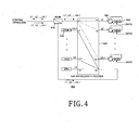
- Fig. 4 illustrates construction of a subscriber-side apparatus according to a first embodiment of the present invention.
- the subscriber-side apparatus 500 includes a WDM filter 510, a wavelength router 520, a plurality of optical receivers 530, a plurality of circulators 540, and a plurality of modulators 550.
- the WDM filter 510 is provided with first to third ports.
- the WDM filter 510 allows the multi-wavelength light and downstream optical signals from the central office 200 to be received through the first port, in which the multi-wavelength light is outputted through the second port and the downstream optical signals are outputted through the third port. Further, the WDM filter allows the upstream optical signals inputted through the second port to be transmitted through the first port to the central office 200.
- the wavelength router 520 comprises first and second multiplexing ports L, and R N , and first and second demultiplexing multi-ports L 2 to L N and R 1 to R N-1 .
- the wavelength router 520 demultiplexes the multi-wavelength light inputted through the first multiplexing port L 1 into a plurality of channels, and then outputs the demultiplexed channels to the second demultiplexing multi-ports R 1 to R N-1 . Further, the wavelength router 520 demultiplexes the downstream optical signals inputted through the second multiplexing port R N into a plurality of channels, and then outputs the demultiplexed channels to the first demultiplexing multi-ports L 2 to L N .
- the wavelength router 520 may, for example, make use of an element which has a periodicity like an NxN arrayed waveguide grating and performs multiplexing and demultiplexing in both directions.
- the plurality of optical receivers 530 are connected with the first demultiplexing multi-ports L 2 to L N respectively, in a one-to-one correspondence and convert a plurality of channels outputted through the first demultiplexing multi-ports L 2 to L N into a separate electrical signal.
- the optical receiver 530 may make use of a photodiode, for example.
- the plurality of circulators 540 are connected with the second demultiplexing multi-ports R 1 to R N-1 respectively, in a one-to-one correspondence, and are provided with first to third ports. Each of the circulators 540 outputs channels inputted through the second port to the third port and outputs channels inputted through the first port to the second port.
- the plurality of modulators 550 are connected with the plurality of circulators 540 respectively, in a one-to-one correspondence. Each of the modulators 550 causes channels inputted through the third port of each corresponding circulator 540 to be modulated with the corresponding data signal and to be outputted to the first port of the circulator 540.
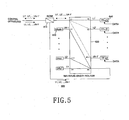
- Fig. 5 illustrates construction of a subscriber-side apparatus according to a second embodiment of the present invention.
- the subscriber-side apparatus 600 includes a WDM filter 610, a wavelength router 620, a plurality of optical receivers 630, and a plurality of Fabry-Perot laser diodes 640.
- the Fig. 5 embodiment differs from that of Fig. 4 in that Fabry-Perot laser diodes 640 are used in place of the combination of circulators 540 and modulators 550. Therefore, analogous parts of the description will not be repeated herein.
- the plurality of Fabry-Perot laser diodes 640 are respectively connected with the second demultiplexing multi-ports R 1 to R N-1 of the wavelength router 620 in a one-to-one correspondence.
- the Fabry-Perot laser diodes 640 are self-locked by inputted respective channels, causing each channel of the self-locked wavelengths to be modulated with the corresponding data signal before being outputted.
- a prior art method spectrum-slices non-coherent ASE and then injects the spectrum-sliced results into a Fabry-Perot laser diode, thereby locking a multi-mode of the Fabry-Perot laser diode to a single mode.
- this method requires a specialized technology, because it demands a high power of ASE and a narrow bandwidth of spliced spectrum.
- light of a relatively high power and a relatively narrow bandwidth can be inputted into the plurality of Fabry-Perot laser diodes 640. Therefore, locking efficiency and locking stability can be obtained.
- Fig. 6 illustrates construction of a subscriber-side apparatus according to a third embodiment of the present invention.
- the subscriber-side apparatus 700 includes a wavelength division multiplexer 710, a plurality of WDM filters 720, a plurality of optical receivers 750, a plurality of circulators 730, and a plurality of modulators 740.
- the wavelength division multiplexer 710 comprises a single multiplexing port L 1 and a plurality of demultiplexing ports R 1 to R N-1 .
- the wavelength division multiplexer 710 demultiplexes inputted respective multi-wavelength light and downstream optical signals into a plurality of channels and then outputs the demultiplexed channels to the plurality of demultiplexing ports R 1 to R N-1 or otherwise multiplexes channels inputted through the plurality of demultiplexing ports R 1 to R N-1 , and then transmits the multiplexed channels to the central office 200.
- the plurality of WDM filters 720 are connected with the plurality of demultiplexing ports R 1 to R N-1 respectively, in a one-to-one correspondence, and are provided with first to third ports.
- each WDM filter 720 of channels inputted through the first port, those constituting the multi-wavelength light are outputted through the second port and those constituting the downstream optical signals are outputted through the third port. Further, channels inputted through the second port are outputted to the first port.
- the plurality of circulators 730 are connected with the plurality of WDM filters 720 respectively, in a one-to one correspondence, and are provided with first to third ports. Each of the circulators 730 outputs to the third port the channels having been inputted through the second port and outputs to the second port the channels having been inputted through the first port.
- the plurality of modulators 740 are connected with the plurality of circulators 730 respectively, in a one-to-one correspondence.
- Each of the modulators 740 causes channels inputted through the third port of each corresponding circulator 730 to be modulated with the corresponding data signal, and then outputs the modulated channels to the first port of the circulator 730.
- the plurality of optical receivers 750 are connected with the plurality of WDM filters 720 in a one-to-one correspondence. Each of the optical receivers 750 converts channels inputted through the third port of each corresponding WDM filter 720 into a separate electrical signal.
- the optical receiver 750 may make use of a photodiode, for example.
- Fig. 7 illustrates construction of a subscriber-side apparatus according to a fourth embodiment of the present invention.
- the subscriber-side apparatus 800 includes a wavelength division multiplexer 810, a plurality of WDM filters 820, a plurality of optical receivers 840, and a plurality of Fabry-Perot laser diodes 830.
- the Fig. 7 embodiment differs from that of Fig. 6 only in that Fabry-Perot laser diodes 830 are used in place of the combination of circulators 730 and modulators 740. Therefore, corresponding parts of the description will not be repeated herein.
- the plurality of Fabry-Perot laser diodes 830 are connected with the plurality of WDM filters 820 respectively, in a one-to-one correspondence. As the Fabry-Perot laser diodes 830 are self-locked by channels inputted through the second port of each corresponding WDM filter 820, the laser diodes 830 cause each channel of the self-locked wavelengths to be modulated with the corresponding data signal and then outputs the modulated channels.
- the WDM passive optical network using a loop back of multi-wavelength light generated from the central office in accordance with the present invention has advantages in that the multi-wavelength light for upstream optical signals to be transmitted from subscribers is generated at the central office and then supplied to the subscribers, so that the optical network can be efficiently operated, and cost effectiveness can be obtained in proportion to the increase in number of subscribers.
- use of laser light as the multi wavelength light provides the optical network with a large enough capability to contain a high volume of data for the subscribers.
Landscapes
- Engineering & Computer Science (AREA)
- Computer Networks & Wireless Communication (AREA)
- Signal Processing (AREA)
- Physics & Mathematics (AREA)
- Electromagnetism (AREA)
- Optical Communication System (AREA)
Applications Claiming Priority (2)
| Application Number | Priority Date | Filing Date | Title |
|---|---|---|---|
| KR2002068846 | 2002-11-07 | ||
| KR10-2002-0068846A KR100480246B1 (ko) | 2002-11-07 | 2002-11-07 | 중앙 기지국에서 생성된 다파장 광의 루프백을 이용하는수동형 광통신망 |
Publications (2)
| Publication Number | Publication Date |
|---|---|
| EP1418691A2 true EP1418691A2 (fr) | 2004-05-12 |
| EP1418691A3 EP1418691A3 (fr) | 2007-05-30 |
Family
ID=32105676
Family Applications (1)
| Application Number | Title | Priority Date | Filing Date |
|---|---|---|---|
| EP03025678A Withdrawn EP1418691A3 (fr) | 2002-11-07 | 2003-11-07 | Réseau optique passif utilisant une lumière multilongueurs d'ondes générée en boucle au central |
Country Status (5)
| Country | Link |
|---|---|
| US (1) | US7254344B2 (fr) |
| EP (1) | EP1418691A3 (fr) |
| JP (1) | JP3978168B2 (fr) |
| KR (1) | KR100480246B1 (fr) |
| CN (1) | CN100342677C (fr) |
Cited By (4)
| Publication number | Priority date | Publication date | Assignee | Title |
|---|---|---|---|---|
| EP1580907A1 (fr) * | 2004-03-25 | 2005-09-28 | Lucent Technologies Inc. | Méthode, dispositif et système de communication de services dans un réseau d'accès optique |
| EP1612974A1 (fr) | 2004-06-28 | 2006-01-04 | Lucent Technologies Inc. | Protocole et fréquence de ligne transparent dans un réseau optique passif avec multiplexage en longueur d'onde |
| US7386235B2 (en) | 2004-06-28 | 2008-06-10 | Lucent Technologies Inc. | Protocol and line-rate transparent WDM passive optical network |
| EP2285019A4 (fr) * | 2008-05-09 | 2012-03-14 | Huawei Tech Co Ltd | Système, appareil et procédé de communication optique |
Families Citing this family (34)
| Publication number | Priority date | Publication date | Assignee | Title |
|---|---|---|---|---|
| KR100325687B1 (ko) * | 1999-12-21 | 2002-02-25 | 윤덕용 | 주입된 비간섭성 광에 파장 잠김된 페브리-페롯 레이저다이오드를 이용한 파장분할 다중방식 광통신용 광원 |
| KR100469736B1 (ko) * | 2002-11-21 | 2005-02-02 | 삼성전자주식회사 | 다파장 레이징 광원에 파장 잠김된 페브리-페롯 레이저장치 및 이를 이용한 광 전송장치 |
| KR100955129B1 (ko) * | 2003-05-30 | 2010-04-28 | 정보통신연구진흥원 | 비간섭성 광대역 광원을 이용한 파장분할다중방식 수동형 광 네트워크 구현 방법 |
| KR100498954B1 (ko) * | 2003-08-27 | 2005-07-04 | 삼성전자주식회사 | 루프-백 광원을 이용한 파장분할다중방식 수동형 광가입자망의 광 파장 트래킹 장치 및 방법 |
| JP4541053B2 (ja) * | 2004-07-08 | 2010-09-08 | 日本電信電話株式会社 | 光伝送システム |
| KR100678245B1 (ko) | 2004-12-01 | 2007-02-02 | 삼성전자주식회사 | 수동형 광 가입자 망 |
| KR100640456B1 (ko) * | 2005-02-01 | 2006-10-31 | 삼성전자주식회사 | 누화없는 파장분할다중방식 수동형 광 가입자망과 그 누화제거 방법 |
| KR100698766B1 (ko) * | 2005-09-07 | 2007-03-23 | 한국과학기술원 | 파장분할 다중방식 수동형 광 가입자 망 시스템에 사용되는장애 위치 감시 장치 및 이를 구비한 파장분할 다중방식수동형 광 가입자 망 시스템 |
| KR100785436B1 (ko) | 2005-09-20 | 2007-12-13 | 한국과학기술원 | 방송 서비스와 통신 서비스를 융합한 파장분할 다중방식수동형 광 가입자망 |
| US7440701B2 (en) * | 2005-12-13 | 2008-10-21 | Broadway Networks, Ltd. | Fiber-to-the-premise optical communication system |
| US7450848B2 (en) * | 2006-04-28 | 2008-11-11 | Broadway Networks, Ltd, | High-speed fiber-to-the-premise optical communication system |
| WO2007129993A1 (fr) * | 2006-05-09 | 2007-11-15 | Agency For Science, Technology And Research | Système détecteur à modulation par répartition en longueur d'onde et système d'interrogation de détecteurs |
| US7317874B2 (en) * | 2006-06-02 | 2008-01-08 | Broadway Networks, Inc. | Adaptive optical transceiver for fiber access communications |
| CN101490987A (zh) * | 2006-07-20 | 2009-07-22 | 法国电信公司 | 使用光学放大信号的非现场调制的长距离无源光网络 |
| US8571410B2 (en) * | 2006-10-11 | 2013-10-29 | Novera Optics, Inc. | Mutual wavelength locking in WDM-PONS |
| US20080089699A1 (en) * | 2006-10-17 | 2008-04-17 | Wen Li | Methods for automatic tuning optical communication system |
| US20080279567A1 (en) * | 2007-05-09 | 2008-11-13 | Wen Huang | Asymmetric ethernet optical network system |
| US20090116845A1 (en) * | 2007-11-02 | 2009-05-07 | Wen Li | Tetintelligent optical transceiver capable of optical-layer management |
| US7933518B2 (en) * | 2008-02-21 | 2011-04-26 | Finisar Corporation | Intelligent optical systems and methods for optical-layer management |
| US7974537B2 (en) * | 2008-06-05 | 2011-07-05 | Finisar Corporation | Intelligent pluggable transceiver stick capable of diagnostic monitoring and optical network management |
| US7957650B2 (en) | 2008-06-26 | 2011-06-07 | Finisar Corporation | Pluggable optical network unit capable of status indication |
| US9246590B2 (en) * | 2009-02-22 | 2016-01-26 | Finisar Corporation | Smart optical transceiver having integrated optical dying gasp function |
| US8880716B2 (en) * | 2009-05-08 | 2014-11-04 | Canon Kabushiki Kaisha | Network streaming of a single data stream simultaneously over multiple physical interfaces |
| US8396960B2 (en) * | 2009-05-08 | 2013-03-12 | Canon Kabushiki Kaisha | Efficient network utilization using multiple physical interfaces |
| US8325601B2 (en) * | 2009-05-08 | 2012-12-04 | Canon Kabushiki Kaisha | Reliable network streaming of a single data stream over multiple physical interfaces |
| US8098426B2 (en) * | 2009-05-20 | 2012-01-17 | Buabbud George | Two-way amplifier for passive optical network (PON) |
| US8356109B2 (en) | 2010-05-13 | 2013-01-15 | Canon Kabushiki Kaisha | Network streaming of a video stream over multiple communication channels |
| TWI416895B (zh) * | 2010-12-07 | 2013-11-21 | Ind Tech Res Inst | 點對點光網路訊號傳送方法與其系統 |
| CN102324983B (zh) * | 2011-06-10 | 2014-08-06 | 复旦大学 | 基于迈克尔逊干涉仪的光域多波长信号产生系统 |
| JP5941150B2 (ja) * | 2011-09-08 | 2016-06-29 | オーエフエス ファイテル,エルエルシー | 共存するgponおよびxgpon光通信システムを配置するための構成 |
| EP2929640B1 (fr) * | 2012-12-10 | 2019-03-27 | Telefonaktiebolaget LM Ericsson (publ) | Commande de puissance dans une liaison optique wdm bidirectionnelle |
| US9178610B1 (en) | 2013-03-14 | 2015-11-03 | Google Inc. | Optical loopback in a wavelength division multiplexing system |
| US9806817B2 (en) * | 2013-05-31 | 2017-10-31 | Telekom Malaysia Berhad | Wavelength division multiplexing passive optical network system |
| US11985056B1 (en) | 2023-07-18 | 2024-05-14 | Bank Of America Corporation | System and method for selective data routing in a distributed network via data throughput analysis |
Family Cites Families (17)
| Publication number | Priority date | Publication date | Assignee | Title |
|---|---|---|---|---|
| EP0615358B1 (fr) * | 1993-03-11 | 2004-10-20 | AT&T Corp. | Réseau optique basé sur l'interrogation à distance d'un équipement terminal |
| US5815295A (en) * | 1993-03-11 | 1998-09-29 | Lucent Technologies Inc. | Optical communication system with improved maintenance capabilities |
| US5550666A (en) * | 1994-06-17 | 1996-08-27 | Lucent Technologies Inc. | Wavelength division multiplexed multi-frequency optical source and broadband incoherent optical source |
| US5680234A (en) * | 1994-10-20 | 1997-10-21 | Lucent Technologies Inc. | Passive optical network with bi-directional optical spectral slicing and loop-back |
| JPH1093164A (ja) * | 1996-09-17 | 1998-04-10 | Kokusai Denshin Denwa Co Ltd <Kdd> | 多波長光源及び離散波長可変光源 |
| US5978119A (en) * | 1997-02-18 | 1999-11-02 | Lucent Technologies Inc. | System and method for synchronizing an optical source and a router in a wavelength division multiplexed fiber optic network |
| KR100251692B1 (ko) * | 1997-09-12 | 2000-04-15 | 윤종용 | 광섬유 가입자 망 |
| US6118565A (en) * | 1997-09-30 | 2000-09-12 | Lucent Technologies Inc. | Coherent optical communication system |
| KR100330409B1 (ko) * | 1998-07-23 | 2002-08-27 | 한국과학기술원 | 파장분할다중 방식 다중화/역다중화 장치와 이를 이용한 파장분할다중 방식 수동형 광 가입자망 |
| JP3589604B2 (ja) | 1999-12-16 | 2004-11-17 | 日本電信電話株式会社 | 波長多重双方向光伝送方法および装置 |
| KR100325687B1 (ko) * | 1999-12-21 | 2002-02-25 | 윤덕용 | 주입된 비간섭성 광에 파장 잠김된 페브리-페롯 레이저다이오드를 이용한 파장분할 다중방식 광통신용 광원 |
| IT1319811B1 (it) * | 2000-01-26 | 2003-11-03 | Cit Alcatel | Metodo di aggiornamento di reti in fibra ottica ms-spring |
| JP3615476B2 (ja) | 2000-10-05 | 2005-02-02 | 日本電信電話株式会社 | 光アクセスシステム、アクセスノード装置およびユーザノード装置 |
| US20020145775A1 (en) * | 2001-04-06 | 2002-10-10 | Quantum Bridge Communications, Inc. | TDM/WDMA passive optical network |
| US7254330B2 (en) * | 2001-07-20 | 2007-08-07 | Tellabs Bedford, Inc. | Single fiber passive optical network wavelength division multiplex overlay |
| KR100480540B1 (ko) * | 2002-04-30 | 2005-04-06 | 주식회사 코어세스 | 광가입자단의 파장제어가 가능한 파장분할다중방식 수동형광가입자망 시스템 |
| JP4342330B2 (ja) * | 2003-11-14 | 2009-10-14 | ユニ・チャーム株式会社 | 使い捨て着用物品 |
-
2002
- 2002-11-07 KR KR10-2002-0068846A patent/KR100480246B1/ko not_active Expired - Fee Related
-
2003
- 2003-05-01 US US10/427,284 patent/US7254344B2/en not_active Expired - Fee Related
- 2003-06-16 CN CNB031427286A patent/CN100342677C/zh not_active Expired - Fee Related
- 2003-11-04 JP JP2003374739A patent/JP3978168B2/ja not_active Expired - Fee Related
- 2003-11-07 EP EP03025678A patent/EP1418691A3/fr not_active Withdrawn
Cited By (7)
| Publication number | Priority date | Publication date | Assignee | Title |
|---|---|---|---|---|
| EP1580907A1 (fr) * | 2004-03-25 | 2005-09-28 | Lucent Technologies Inc. | Méthode, dispositif et système de communication de services dans un réseau d'accès optique |
| US7684704B2 (en) | 2004-03-25 | 2010-03-23 | Alcatel-Lucent Usa Inc. | Method, apparatus and system for the communication of services in an optical access network |
| EP1612974A1 (fr) | 2004-06-28 | 2006-01-04 | Lucent Technologies Inc. | Protocole et fréquence de ligne transparent dans un réseau optique passif avec multiplexage en longueur d'onde |
| US7386235B2 (en) | 2004-06-28 | 2008-06-10 | Lucent Technologies Inc. | Protocol and line-rate transparent WDM passive optical network |
| EP2285019A4 (fr) * | 2008-05-09 | 2012-03-14 | Huawei Tech Co Ltd | Système, appareil et procédé de communication optique |
| AU2009243970B2 (en) * | 2008-05-09 | 2012-10-25 | Huawei Technologies Co., Ltd. | Optical communication system, apparatus and method |
| CN101577842B (zh) * | 2008-05-09 | 2013-08-07 | 华为技术有限公司 | 一种光通信系统、装置和方法 |
Also Published As
| Publication number | Publication date |
|---|---|
| US7254344B2 (en) | 2007-08-07 |
| JP3978168B2 (ja) | 2007-09-19 |
| KR100480246B1 (ko) | 2005-04-07 |
| CN100342677C (zh) | 2007-10-10 |
| EP1418691A3 (fr) | 2007-05-30 |
| CN1499769A (zh) | 2004-05-26 |
| JP2004159328A (ja) | 2004-06-03 |
| KR20040040659A (ko) | 2004-05-13 |
| US20040091265A1 (en) | 2004-05-13 |
Similar Documents
| Publication | Publication Date | Title |
|---|---|---|
| US7254344B2 (en) | Passive optical network using loop back of multi-wavelength light generated at central office | |
| JP4584584B2 (ja) | 波長分割多重パッシーブ光ネットワークを含むシステムおよびそのための方法 | |
| KR100480540B1 (ko) | 광가입자단의 파장제어가 가능한 파장분할다중방식 수동형광가입자망 시스템 | |
| US6996138B2 (en) | Fabry-Perot laser apparatus mode-locked to multi-frequency lasing light source and optical transmission apparatus using the same | |
| Jung et al. | Wavelength-division-multiplexed passive optical network based on spectrum-slicing techniques | |
| US5696615A (en) | Wavelength division multiplexed optical communication systems employing uniform gain optical amplifiers | |
| US7389048B2 (en) | Optical wavelength-division multiple access system and optical network unit | |
| US6704139B2 (en) | Optical systems and methods and optical amplifiers for use therein | |
| JP5941150B2 (ja) | 共存するgponおよびxgpon光通信システムを配置するための構成 | |
| US6597482B1 (en) | Multiplexing/demultiplexing apparatus for wavelength division multiplexed system and wavelength division multiplexed passive optical subscriber networks using the same apparatus | |
| EP1411655B1 (fr) | Dispositif laser Fabry-Perot auto-activé pour un système à multiplexage en longueurs d'onde | |
| CN101946430A (zh) | 波分复用-无源光网络系统 | |
| JP2005073257A (ja) | 多波長光送信器及びこれを用いた両方向波長分割多重システム | |
| US7155124B2 (en) | Loss-less architecture and method for wavelength division multiplexing (WDM) optical networks | |
| US7398021B2 (en) | Optical transmitter and passive optical network using the same | |
| US20060233550A1 (en) | Wavelength division multiplexed light source and passive optical network using the same | |
| JP3971360B2 (ja) | 波長分割多重光通信システムの光源発生装置 | |
| KR20060064467A (ko) | 광 전송 장치 및 방법 | |
| US11189986B2 (en) | Low-noise Raman amplifier | |
| KR100605905B1 (ko) | 이종광원을 이용한 수동형 광 가입자망 | |
| KR100923503B1 (ko) | 비디오 오버레이 기능을 갖춘 더블유디엠-폰 시스템 | |
| JP2002314507A (ja) | スペクトルスライス光伝送方法および伝送装置 | |
| Chapman | Department of Telematics Faculty of Technology |
Legal Events
| Date | Code | Title | Description |
|---|---|---|---|
| PUAI | Public reference made under article 153(3) epc to a published international application that has entered the european phase |
Free format text: ORIGINAL CODE: 0009012 |
|
| 17P | Request for examination filed |
Effective date: 20031107 |
|
| AK | Designated contracting states |
Kind code of ref document: A2 Designated state(s): AT BE BG CH CY CZ DE DK EE ES FI FR GB GR HU IE IT LI LU MC NL PT RO SE SI SK TR |
|
| AX | Request for extension of the european patent |
Extension state: AL LT LV MK |
|
| PUAL | Search report despatched |
Free format text: ORIGINAL CODE: 0009013 |
|
| AK | Designated contracting states |
Kind code of ref document: A3 Designated state(s): AT BE BG CH CY CZ DE DK EE ES FI FR GB GR HU IE IT LI LU MC NL PT RO SE SI SK TR |
|
| AX | Request for extension of the european patent |
Extension state: AL LT LV MK |
|
| AKX | Designation fees paid |
Designated state(s): DE FR GB |
|
| 17Q | First examination report despatched |
Effective date: 20090910 |
|
| STAA | Information on the status of an ep patent application or granted ep patent |
Free format text: STATUS: THE APPLICATION IS DEEMED TO BE WITHDRAWN |
|
| 18D | Application deemed to be withdrawn |
Effective date: 20100121 |