EP1418714B1 - Sendevorrichtung und Verfahren zur Bandbreitenzuteilung - Google Patents
Sendevorrichtung und Verfahren zur Bandbreitenzuteilung Download PDFInfo
- Publication number
- EP1418714B1 EP1418714B1 EP02360306A EP02360306A EP1418714B1 EP 1418714 B1 EP1418714 B1 EP 1418714B1 EP 02360306 A EP02360306 A EP 02360306A EP 02360306 A EP02360306 A EP 02360306A EP 1418714 B1 EP1418714 B1 EP 1418714B1
- Authority
- EP
- European Patent Office
- Prior art keywords
- transmitter
- parameter
- control unit
- connection
- bandwidth
- Prior art date
- Legal status (The legal status is an assumption and is not a legal conclusion. Google has not performed a legal analysis and makes no representation as to the accuracy of the status listed.)
- Expired - Lifetime
Links
- 238000000034 method Methods 0.000 title claims abstract description 11
- 230000000737 periodic effect Effects 0.000 claims description 7
- 238000004364 calculation method Methods 0.000 claims description 5
- 238000011156 evaluation Methods 0.000 claims description 2
- 238000004891 communication Methods 0.000 description 14
- 230000005540 biological transmission Effects 0.000 description 11
- 230000008901 benefit Effects 0.000 description 4
- 230000006870 function Effects 0.000 description 3
- 229920006235 chlorinated polyethylene elastomer Polymers 0.000 description 2
- 238000000136 cloud-point extraction Methods 0.000 description 2
- 230000001419 dependent effect Effects 0.000 description 2
- 238000010586 diagram Methods 0.000 description 2
- 230000007246 mechanism Effects 0.000 description 2
- 238000004088 simulation Methods 0.000 description 2
- 238000013459 approach Methods 0.000 description 1
- 230000001276 controlling effect Effects 0.000 description 1
- 230000001934 delay Effects 0.000 description 1
- 230000007774 longterm Effects 0.000 description 1
- 238000013507 mapping Methods 0.000 description 1
- 230000002093 peripheral effect Effects 0.000 description 1
- 238000012545 processing Methods 0.000 description 1
- 230000001105 regulatory effect Effects 0.000 description 1
- 230000004044 response Effects 0.000 description 1
- 230000001629 suppression Effects 0.000 description 1
- 230000002459 sustained effect Effects 0.000 description 1
- 238000012546 transfer Methods 0.000 description 1
Images

Classifications
-
- H—ELECTRICITY
- H04—ELECTRIC COMMUNICATION TECHNIQUE
- H04W—WIRELESS COMMUNICATION NETWORKS
- H04W28/00—Network traffic management; Network resource management
- H04W28/16—Central resource management; Negotiation of resources or communication parameters, e.g. negotiating bandwidth or QoS [Quality of Service]
- H04W28/18—Negotiating wireless communication parameters
- H04W28/20—Negotiating bandwidth
-
- H—ELECTRICITY
- H04—ELECTRIC COMMUNICATION TECHNIQUE
- H04L—TRANSMISSION OF DIGITAL INFORMATION, e.g. TELEGRAPHIC COMMUNICATION
- H04L47/00—Traffic control in data switching networks
- H04L47/70—Admission control; Resource allocation
-
- H—ELECTRICITY
- H04—ELECTRIC COMMUNICATION TECHNIQUE
- H04L—TRANSMISSION OF DIGITAL INFORMATION, e.g. TELEGRAPHIC COMMUNICATION
- H04L47/00—Traffic control in data switching networks
- H04L47/70—Admission control; Resource allocation
- H04L47/76—Admission control; Resource allocation using dynamic resource allocation, e.g. in-call renegotiation requested by the user or requested by the network in response to changing network conditions
- H04L47/765—Admission control; Resource allocation using dynamic resource allocation, e.g. in-call renegotiation requested by the user or requested by the network in response to changing network conditions triggered by the end-points
-
- H—ELECTRICITY
- H04—ELECTRIC COMMUNICATION TECHNIQUE
- H04L—TRANSMISSION OF DIGITAL INFORMATION, e.g. TELEGRAPHIC COMMUNICATION
- H04L47/00—Traffic control in data switching networks
- H04L47/70—Admission control; Resource allocation
- H04L47/80—Actions related to the user profile or the type of traffic
- H04L47/801—Real time traffic
-
- H—ELECTRICITY
- H04—ELECTRIC COMMUNICATION TECHNIQUE
- H04L—TRANSMISSION OF DIGITAL INFORMATION, e.g. TELEGRAPHIC COMMUNICATION
- H04L47/00—Traffic control in data switching networks
- H04L47/70—Admission control; Resource allocation
- H04L47/80—Actions related to the user profile or the type of traffic
- H04L47/805—QOS or priority aware
-
- H—ELECTRICITY
- H04—ELECTRIC COMMUNICATION TECHNIQUE
- H04L—TRANSMISSION OF DIGITAL INFORMATION, e.g. TELEGRAPHIC COMMUNICATION
- H04L47/00—Traffic control in data switching networks
- H04L47/70—Admission control; Resource allocation
- H04L47/80—Actions related to the user profile or the type of traffic
- H04L47/808—User-type aware
-
- H—ELECTRICITY
- H04—ELECTRIC COMMUNICATION TECHNIQUE
- H04L—TRANSMISSION OF DIGITAL INFORMATION, e.g. TELEGRAPHIC COMMUNICATION
- H04L47/00—Traffic control in data switching networks
- H04L47/70—Admission control; Resource allocation
- H04L47/82—Miscellaneous aspects
- H04L47/824—Applicable to portable or mobile terminals
-
- H—ELECTRICITY
- H04—ELECTRIC COMMUNICATION TECHNIQUE
- H04W—WIRELESS COMMUNICATION NETWORKS
- H04W72/00—Local resource management
- H04W72/04—Wireless resource allocation
- H04W72/044—Wireless resource allocation based on the type of the allocated resource
- H04W72/0453—Resources in frequency domain, e.g. a carrier in FDMA
-
- H—ELECTRICITY
- H04—ELECTRIC COMMUNICATION TECHNIQUE
- H04W—WIRELESS COMMUNICATION NETWORKS
- H04W84/00—Network topologies
- H04W84/02—Hierarchically pre-organised networks, e.g. paging networks, cellular networks, WLAN [Wireless Local Area Network] or WLL [Wireless Local Loop]
- H04W84/10—Small scale networks; Flat hierarchical networks
- H04W84/14—WLL [Wireless Local Loop]; RLL [Radio Local Loop]
Definitions
- the present invention relates to a method for allocating bandwidth on-demand to a constant bit rate connection in a wireless MAN access network, in particular in a LMDS access network, a transmitter for wireless MAN access networks, in particular for LMDS access networks, where bandwidth is allocated on-demand to one or several constant bit rate connections, and to a subscriber station for wireless MAN access networks.
- WO 02/05453 describes several methods of bandwidth allocation.
- a specific kind of bandwidth request protocol is proposed which utilises a combination of incremental and aggregate bandwidth requests in order to yield a particularly effective self-correcting of errors.
- Incremental bandwidth requests identify the additional bandwidth requirements of the CPE (Customer Premises Equipment), whereas aggregate bandwidth requests quantify the current total bandwidth requirement.
- the bandwidth request is issued as a 5-byte message.
- the base station polls the CPE to respond with a bandwidth request in a subsequent uplink frame.
- the polling of the CPE by the base station may be in response to a CPE setting a "poll-me bit".
- the bandwidth is allocated by the base station taking into account QoS parameters, fairness criteria, and priorities of the CPEs. For this weighting mechanism, the amount of data pending expressed as a percentage of the total data pending in the queue may be used.
- request timers are used that allow the transmission of request inly after a periodic pre-determined time interval.
- LMDS Local Multipoint Distribution Service
- a field in the grant management sub-header is used to pass status information from the subscriber station to the base station. This status information regards the state of the unsolicited grant service flow.
- the unsolicited grant service is designed to support real-time service flows that generate fixed size data packets on periodic bases, such as D1/E1 and voice over IP without silence suppression.
- the service offers fixed size grants on real-time periodic bases, which eliminates the overhead and latency of subscriber service requests and ensures that grants are variable to meet the flows real time needs.
- the most significant bit of the grant management sub-header is the slip indicator bit.
- the subscriber station shall set this flag once it detects that this service flow has exceeded it's transmit queue depth. Once the subscriber station detects that the service flows transmit queue is back within limits, it shall clear the slip indicator flag.
- the flag allows the base station to provide for long term compensation of conditions such as lost maps or clock rate mismatches by issuing additional grants.
- the base station does not allocate more bandwidth than the maximum sustained traffic rate parameter of the active quality of service parameters, excluding the case when the slip indicator bit of the grant management sub-header is set. In this case, the base station may grant up to 1 % additional bandwidth for clock rate mismatch compensation.
- It is the object of the present invention to improve constant bit rate services provided in wireless MAN access networks, in particular in LMDS access networks (MAN Metropolitan Area Network).
- the object of the present invention is achieved by a method for allocating bandwidth on-demand to a constant bit rate connection in a wireless MAN access network, in particular in a LMDS access network, said method comprising the steps of: sending from a transmitter a data packet to a receiver, the data packet comprises a parameter indicating whether additional bandwidth is required for jitter compensation; allocating additional bandwidth to the connection based on said parameter; and setting said parameter based on the time data has spent in a transmit queue assigned to the connection at the transmitter.
- the object of the present invention is further achieved by a transmitter for wireless MAN access networks, in particular for LMDS access networks, where the bandwidth is allocated on-demand to one or several constant bit rate connections, the transmitter comprising: a connection control unit for generating data packets assigned to the connection and sent to a receiver, the generated data packets comprise a parameter indicating whether additional bandwidth is required for jitter compensation to request allocation of additional bandwidth to the connection based on said parameter; and a parameter control unit for setting said parameter based on the time data have spent in the transmit queue assigned to the connection at the transmitter.
- a subscriber station for wireless MAN access networks in particular for LMDS access networks, the subscriber station comprises such kind of transmitter.
- the invention makes it possible to decrease drastically the end-to-end delays of constant bit rate connections. This causes better quality of service performance.
- the invention reduces the delay time data spent in transmit queues, independent on the queue fill level.
- the present invention overcomes following disadvantages of existing solutions: According to existing solutions, the bandwidth is only increased, if some data remain in the queue when data transfer is finalized. These remaining data has to wait for the next grant. Therefore, the delay of these packets is in the range of the grant period.
- the grant period itself is a multiple of the frame length and may vary, too. Further, to get the control loop working, the queue can not be empty.
- the present invention can be easily implemented into existing system. No changes have to be performed in the air interface specification. Further, the receiver side has not to be changed. Consequently, big improvements can be reached by low implementation effort.
- fixed size grants are allocated at periodic intervals to the connections, wherein a grant includes several packets. Simulation results show that substantial improvements of delay times are achievable for such constellations.
- the parameter control unit sets said parameter, if data have spent a time longer than a predefined threshold delay in the transmit queue.
- PI Proportional Integral
- the parameter control unit performs parameter setting calculations for all packets of a grant. Thereby, it is not necessary to determine the last packet of the grant. This helps to save additional investments in such kind of recognition logic.
- the parameter control unit assigns a time-stamp to each packet inserted in a transmit queue, evaluates the time-stamp when transmitting the corresponding packets to the receiver and calculates packet delay times based on said evaluation. This allows an efficient and cost-saving implementation of the invention.
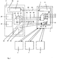
- Fig. 1 shows a communication system.
- This communication system is a communication system according to IEE802.16.
- the communication system is any other kind of wireless MAN access network system.
- the system of Fig. 1 is a communication system according to ETSI BRAN.
- the communication system of Fig. 1 has some subscriber stations 2 to 5 and a base station 0 with a receiver 1. Data are exchanged between the subscriber stations 2 to 5 and the base station 1 via an air interface. Consequently, the base station 0 and the subscriber stations 2 to 5 utilize a shared medium which requires a mechanism to efficiently share it.
- the down-link from the base station to the subscriber stations operates on point-to-multipoint bases. Within a given frequency channel and antenna sector all stations receive the same transmission.
- the base station is the only transmitter operating in this direction, so it transmits without having to coordinate with other stations.
- the user stations 2 to 5 share the up-link to the base station on a demand bases.
- the subscriber stations may be issued rights to transmit.
- the details of the subscriber stations 2 to 5 are described in the following by hand of the subscriber station 2.
- the subscriber station 2 is formed by a terminal which comprises an electronic circuit with one or several microprocessors and with several software programs executed by these microprocessors. But, it is also possible that the electronic circuit is a pure hardware implementation. Further, it is possible that the subscriber station 2 is formed by one or several interconnected computer systems which comprise peripheral units enabling the communication over the air interface.
- the functionality of the subscriber station 2 is at least party provided by the execution of software programs by the hardware platform of the subscriber station 2.
- the subscriber station 2 comprises several user applications 29 and 30 and a transmitter 20. Further, the subscriber station 21 may in addition comprise a receiver adapted as the receiver 1 of the base station 1.
- the user applications 29 and 30 are application programs, which request different kind of communication services from the transmitter 20.
- the requested services may defer with respect to delay and bandwidth requirements of the user applications 29 and 30.
- the transmitter 20 may be formed by a pure hardware implemented electronic circuit. But, it is also possible that at least a part of the functionalities of the transmitter 20 is provided by software programs executed by a microprocessor.
- the transmitter 20 comprises a transmission control unit 21 and several connection control units 23 to 28.
- the receiver 1 of the base station 0 is formed by an electronics circuit comprising one or several microprocessors. From the functional point of view it has a transmission control unit 11, an allocation unit 12 and several connection control units 13 to 18.
- the communication between the transmitter 20 and the receiver 1 is connection oriented.
- all data communications are handled in the context of a connection.
- the transmission control units 21 and 11 are responsible for connection establishment and assignment of quality of service parameters to connections.
- connections 60 to 61 are defined between the transmission control units 21 and 11 to allow quality of service management. After registration of a subscriber station, connections are associated with service flows to provide a reference against which to request bandwidth. Additionally, new connections may be established when a user application request changes. Connections between the transmitter 20 and the receiver 1 are created and terminated by the exchange of connection create and connection terminate messages between the transmission control units 21 and 11.
- types of communication service types may be assigned to connections, for example, unsolicited grant service, real-time polling service, non-real-time polling service and best effort service.
- connection control units 23 to 28 and 13 to 18 performs functions for one specific connection defined between the transmitter 20 and the receiver 1.
- the connection control units 23 and 13, 24 and 14, and 25 and 15 perform functions for connections 63, 64 and 65, respectively.
- the control units 26 and 16, 27 and 17, and 28 and 18 perform functions for connections 60, 67 and 68, respectively.
- connections 63, 64 and 65 are constant bit rate connections. In additional to this general service type, each of these connections is specified by individual parameters specifying the grant size, the normal grant interval, the tolerated grant jitter and the request transmission policy. These connections offers fixed size grants on a real-time periodic bases which eliminates the overhead and latency of bandwidth request and ensures that grants are available to meet the flows real-time needs.
- the connections 66, 67 and 68 are variable bit rate connections based on a polling service.
- the bandwidth allocation policy applied to these connections is designed to support real-time service flows that gant variable size data packets on a periodic bases such as MPEG video, but also to support non real-time service flows said require variable size data grant burst types on a regular bases such as high bandwidth FTP.
- the communication service provided by these channels offers unicast polls on regular bases which ensure that flows receive request opportunities even during network congestion.
- the allocation unit 12 allocates the available bandwidth to the subscriber stations 2 to 5 and to the respective connections defined between the subscriber stations 2 to 5 and the base station 1. It performs a dynamic bandwidth allocation which bases on control messages exchanged between the transmission control units 21 and 11 and on control-sub-headers exchanged over the data connections.
- connection control units 13 to 15 monitors a flag within the grant management sub-header of the received packets and report the status of this flag to the allocation unit 12.
- the allocation unit grants up to 1 % additional bandwidth to the associated constant bit rate connection.
- connection control units 16 to 18 monitors a field of the grant management sub-header of received packets, which indicates the size of requested bandwidth. In the case bandwidth is requested, it reports this to the allocation unit 12.
- the allocation unit 12 may grant bandwidth explicitly to each connection or to all the connections belonging to one subscriber station.
- the setting of the above mentioned flag in the grant management sub-header of packets transmitted from the connection control units 23 to 25 to the connection control units 13 to 15, respectively, is controlled base on the time data have spent in a transmit queue assigned to the connection at the transmitter 20.
- connection control unit 40 has a transmit queue 40 used to offer the real-time traffic served by the connection 63.
- the time data have spent within the buffer 40 is monitored and the decision whether to set this flag is based on the monitored packet delay time.
- Fig. 2 shows a part of the connection control unit 23 which comprises the transmit queue 40, a parameter control unit 30 and a control unit 50.
- the parameter control unit 30 contains control units 31 to 35.
- the parameter control unit 30, the transmit queue 40 and the control unit 50 are preferably implemented as pure hardware implementation. But, it is also possible to implement them or a part of them as software implementation.
- the connection control unit 23 receives a data packet 71 which has to be transmitted over the constant bit rate connection 63.
- the control unit 31 assigns a time stamp to this packet. This time stamp is a 16 bit or 32 bit value.
- the control unit 31 appends this value to the data packet 71. Then, it stores the data packet 71 in the transmit queue 40.
- the transmit queue 40 does already contain several data packets 72 to 74. Each of these data packets comprises an attached time stamp 721, 731 and 741, respectively.
- the control unit 50 serves the transmit queue 40.
- a grant is issued to the connection 63, a number of packets are served by the control unit 50.
- the number of served packets dependents on the size of the grant.
- Fig. 2 shows a grant 80 including four data packets 76 to 79.
- the control unit 50 serves four packets of the transmit queue 40. While served by the control unit 50, the time stamps are detached and signaled as signal 82 to the control unit 32.
- control unit 50 generates the data packets sent to the receiver 1. It receives packets from the transmit queue 40, for example a data packet 75, and adds headers to these packets, which are necessary to transmit these data packets over the connection 63 to the connection control unit 13.
- this parameter is a one bit flag which is in the following notified as slip indicator.
- the control unit 32 calculates the packet delay time of the packets served by the control unit 50.
- the control unit 31 receives the signal 82 specifying the time stamps associated to served data packets.
- the signal 82 receives a signal 81 containing synchronization information from the control unit 31.
- control unit 31 contains a counter which is periodically increased by help of a clock signal.
- the control unit 31 generates a time stamp by assigning the present counter value to the data packet presently stored in the transmit queue 40. Further, it signals the present counter value as signal 81 to the control unit 32.
- the control unit 32 calculates the transmission delay time of a data packet by calculating the difference between the values signaled by the signals 81 and 82.
- the control unit 33 calculates the average delay time of the data packets of a grant. It receives a signal 83 from the control unit 32.
- the signal 83 contains information about the delay times of the single packets served by the control unit 50. Further, it receives information from the control unit 50 indicating the issuing of a grant. Therefore, the control unit 33 is in a position to assign individual delay times to grants and calculate the average delay time of the packets of the grant.
- the control unit 34 is a PI filter.
- the I-part of the filter is, for example, implemented by help of a memory and an adder.
- the filter parameters assigned to the P-part and I-part of the PI filter depend on the specific implementation of the method. Simulation results show that a dominant I-part is of advantage.
- the control unit 35 receives the output value of the PI filter.
- the control unit 35 compares this output value with a predetermined threshold. If the output value exceeds this threshold, it sends a signal 86 to the control unit 50 which requests the setting of the slip indicator.
- the parameter control unit 35 sets the slip indication parameter, if data have spent a time longer than a predefined threshold delay in the transmit queue.
- the parameter control unit 30 forms part of a feedback control loop controlling the time data packets spent in the transmit queue 40.
- the regulated parameter is the slip indicator parameter.
Landscapes
- Engineering & Computer Science (AREA)
- Computer Networks & Wireless Communication (AREA)
- Signal Processing (AREA)
- Quality & Reliability (AREA)
- Mobile Radio Communication Systems (AREA)
- Data Exchanges In Wide-Area Networks (AREA)
- Use Of Switch Circuits For Exchanges And Methods Of Control Of Multiplex Exchanges (AREA)
Claims (10)
- Ein Verfahren zur bedarfsgerechten Zuteilung von Bandbreite für eine Verbindung mit konstanter Bitrate (63, 64, 65) in einem drahtlosen MAN-Teilnehmernetz, insbesondere in einem LMDS-Teilnehmernetz,
dadurch gekennzeichnet, dass
das genannte Verfahren die folgenden Schritte umfasst:Versand eines Datenpakets (76 bis 79) vom Sender (20) an einen Empfänger (1), wobei der Header des Datenpakets (76 bis 79) einen Parameter beinhaltet, der angibt, ob zusätzliche Bandbreite zur Jitter-Kompensation benötigt wird;Zuteilung zusätzlicher Bandbreite für die Verbindung (63 bis 65) auf der Basis des genannten Parameters im Header des Datenpakets; undEinstellung des genannten Parameters auf der Basis der Zeit (83), die die Daten in einer sendewarteschlange (40) verbracht haben, die der Verbindung mit konstanter Bitrate (63) am Sender (20) zugeordnet ist. - Verfahren zur Zuteilung von Bandbreite gemäß Anspruch 1,
dadurch gekennzeichnet,
dass das Verfahren außerdem einen Schritt zur Zuteilung von Zuordnungen mit fester Größe (80) für die Verbindung (63 bis 65) in regelmäßigen Intervallen umfasst, wobei eine Zuordnung mehrere Pakete (76 bis 79) beinhaltet. - Ein Sender (20) für drahtlose MAN-Teilnehmernetze, insbesondere für LMDS-Teilnehmernetze, wobei die Bandbreite bedarfsgerecht einer oder mehreren Verbindungen mit konstanter Bitrate (63, 64, 65) zugeteilt wird,
dadurch gekennzeichnet,
dass der Sender (20) Folgendes beinhaltet: eine Verbindungs-Steuereinheit (23, 24, 25) zum Generieren von Datenpaketen (76 bis 79), die der Verbindung (63 bis 65) zugeordnet sind und an einen Empfänger (1) gesandt werden, wobei die Header der generierten Datenpakete (76 bis 79) einen Parameter beinhalten, der angibt, ob zusätzliche Bandbreite zur Jitter-Kompensation erforderlich ist, um die Zuteilung zusätzlicher Bandbreite für die Verbindung (63 bis 65) auf der Basis des genannten Parameters anzufordern; und eine Parameter-Steuereinheit (30) zur Einstellung des genannten Parameters auf der Basis der Zeit, die die Daten in einer Sendewarteschlange (40) verbracht haben, die der Verbindung mit konstanter Bitrate (63, 64, 65) am Sender (20) zugeordnet ist. - Der Sender (20) gemäß Anspruch 3,
dadurch gekennzeichnet,
dass die Parameter-Steuereinheit (30) in der Lage ist, den genannten Parameter einzustellen, wenn die Verzögerungszeit der Daten in der Sendewarteschlange (40) einen vordefinierten Grenzwert überschreitet. - Der Sender (20) gemäß Anspruch 3,
dadurch gekennzeichnet,
dass die Parameter-Steuereinheit (30) in der Lage ist, die Paket-Verzögerungszeiten zu berechnen, indem ein PI-Filter (34) auf die Paket-Verzögerungszeiten angewandt wird, und den genannten Parameter einzustellen, wenn der Ausgangswert des PI-Filters (34) einen vordefinierten Grenzwert übersteigt. - Der Sender (20) gemäß Anspruch 5,
dadurch gekennzeichnet,
dass die Parameter-Steuereinheit (30) in der Lage ist, die durchschnittliche Verzögerungszeit der Pakete einer Zuordnung als Eingangswert für den PI-Filter (34) zu verwenden. - Der Sender (20) gemäß Anspruch 3,
dadurch gekennzeichnet,
dass die Parameter-Steuereinheit (30) in der Lage ist, Berechnungen zur Parameter-Einstellung für alle Pakete (76 bis 79) einer Zuordnung (80) durchzuführen. - Der Sender (20) gemäß Anspruch 3,
dadurch gekennzeichnet,
dass die Parameter-Steuereinheit (30) in der Lage ist, Berechnungen zur Parameter-Einstellung nur für das letzte Paket (67) einer Zuordnung (80) durchzuführen. - Der Sender (20) gemäß Anspruch 3,
dadurch gekennzeichnet, dass
die Parameter-Steuereinheit (30) in der Lage ist, jedem Paket (72, 73, 74), das in die Sendewarteschlange (40) eingestellt wird, einen Zeitztempel (721, 731, 741) zuzuordnen, diese Zeitstempel (721, 731, 741) bei der übermittlung der entsprechenden Pakete (72, 73, 74) an den Empfänger (1) auszuwerten und die Paket-Verzögerungszeiten (83) auf der Basis der genannten Auswertung zu berechnen. - Der Sender (20) gemäß Anspruch 3,
dadurch gekennzeichnet,
dass der Sender (20) Teil einer Teilnehmerstation (2, 3, 4, 5) für ein drahtloses MAN-Teilnehmernetz, insbesondere für ein LMDS-Teilnehmernetz, ist.
Priority Applications (4)
| Application Number | Priority Date | Filing Date | Title |
|---|---|---|---|
| DE60209204T DE60209204T2 (de) | 2002-11-08 | 2002-11-08 | Sendevorrichtung und Verfahren zur Bandbreitenzuteilung |
| EP02360306A EP1418714B1 (de) | 2002-11-08 | 2002-11-08 | Sendevorrichtung und Verfahren zur Bandbreitenzuteilung |
| AT02360306T ATE318038T1 (de) | 2002-11-08 | 2002-11-08 | Sendevorrichtung und verfahren zur bandbreitenzuteilung |
| US10/695,816 US7339951B2 (en) | 2002-11-08 | 2003-10-30 | Transmitter and method for bandwidth allocation |
Applications Claiming Priority (1)
| Application Number | Priority Date | Filing Date | Title |
|---|---|---|---|
| EP02360306A EP1418714B1 (de) | 2002-11-08 | 2002-11-08 | Sendevorrichtung und Verfahren zur Bandbreitenzuteilung |
Publications (2)
| Publication Number | Publication Date |
|---|---|
| EP1418714A1 EP1418714A1 (de) | 2004-05-12 |
| EP1418714B1 true EP1418714B1 (de) | 2006-02-15 |
Family
ID=32104025
Family Applications (1)
| Application Number | Title | Priority Date | Filing Date |
|---|---|---|---|
| EP02360306A Expired - Lifetime EP1418714B1 (de) | 2002-11-08 | 2002-11-08 | Sendevorrichtung und Verfahren zur Bandbreitenzuteilung |
Country Status (4)
| Country | Link |
|---|---|
| US (1) | US7339951B2 (de) |
| EP (1) | EP1418714B1 (de) |
| AT (1) | ATE318038T1 (de) |
| DE (1) | DE60209204T2 (de) |
Families Citing this family (6)
| Publication number | Priority date | Publication date | Assignee | Title |
|---|---|---|---|---|
| JP3841100B2 (ja) * | 2004-07-06 | 2006-11-01 | セイコーエプソン株式会社 | 電子装置および無線通信端末 |
| CN100525191C (zh) * | 2004-08-06 | 2009-08-05 | 中兴通讯股份有限公司 | 无线局域网传输方法 |
| US7733870B1 (en) | 2004-09-10 | 2010-06-08 | Verizon Services Corp. & Verizon Services Organization Inc. | Bandwidth-on-demand systems and methods |
| US7848291B2 (en) * | 2004-11-05 | 2010-12-07 | Interdigital Technology Corporation | Wireless metropolitan area network architecture for managing network resources and mobility |
| CN101110815B (zh) * | 2006-07-17 | 2011-12-07 | 中兴通讯股份有限公司 | 一种无线局域网多速率自适应传输的方法 |
| WO2009118827A1 (ja) * | 2008-03-25 | 2009-10-01 | 富士通株式会社 | フロー情報収集装置 |
Family Cites Families (6)
| Publication number | Priority date | Publication date | Assignee | Title |
|---|---|---|---|---|
| US5432790A (en) * | 1993-09-17 | 1995-07-11 | Motorola, Inc. | Method for allocating internodal link bandwidth in a packet oriented communication network to guarantee delay quality-of-service |
| US6097700A (en) * | 1995-09-18 | 2000-08-01 | Telefonaktiebolaget L M Ericsson (Publ) | Packet switched radio channel congestion control |
| GB2343594A (en) * | 1998-10-09 | 2000-05-10 | Int Mobile Satellite Org | Channel allocation method and apparatus |
| US7006530B2 (en) * | 2000-12-22 | 2006-02-28 | Wi-Lan, Inc. | Method and system for adaptively obtaining bandwidth allocation requests |
| AU2001271969A1 (en) * | 2000-07-11 | 2002-01-21 | Ensemble Communications, Inc. | Method and apparatus for bandwidth request/grant protocols in a wireless communication system |
| KR101196823B1 (ko) * | 2005-07-15 | 2012-11-06 | 삼성전자주식회사 | 일정 비트율 트래픽의 클럭 복원 방법 및 장치 |
-
2002
- 2002-11-08 EP EP02360306A patent/EP1418714B1/de not_active Expired - Lifetime
- 2002-11-08 AT AT02360306T patent/ATE318038T1/de not_active IP Right Cessation
- 2002-11-08 DE DE60209204T patent/DE60209204T2/de not_active Expired - Lifetime
-
2003
- 2003-10-30 US US10/695,816 patent/US7339951B2/en not_active Expired - Fee Related
Also Published As
| Publication number | Publication date |
|---|---|
| US7339951B2 (en) | 2008-03-04 |
| US20040090956A1 (en) | 2004-05-13 |
| DE60209204T2 (de) | 2006-08-03 |
| ATE318038T1 (de) | 2006-03-15 |
| DE60209204D1 (de) | 2006-04-20 |
| EP1418714A1 (de) | 2004-05-12 |
Similar Documents
| Publication | Publication Date | Title |
|---|---|---|
| US9860753B2 (en) | Method and apparatus for bandwidth request/grant protocols in a wireless communication system | |
| EP1310062B1 (de) | Verfahren und System zur Reservierung von Bandbreite in einem Funkkommunikationssystem | |
| US6680930B2 (en) | Method and apparatus for determining and reserving bandwidth for transmitting delay-sensitive streaming data over a radio frequency channel | |
| US7808941B2 (en) | Dynamic adaptation for wireless communications with enhanced quality of service | |
| US7242694B2 (en) | Use of group poll scheduling for broadband communication systems | |
| EP1402689B1 (de) | Methode und vorrichtung zur bereitstellung von kommunikationsbandbreite an benutzer mit garantierter datenrate basierend auf prioritätszuweisung | |
| US6785252B1 (en) | Method and apparatus for a self-correcting bandwidth request/grant protocol in a wireless communication system | |
| US8233500B2 (en) | Context-dependent scheduling through the use of anticipated grants for broadband communication systems | |
| US7123627B2 (en) | Class of computationally parsimonious schedulers for enforcing quality of service over packet based AV-centric home networks | |
| EP1784038B1 (de) | Verfahren zur Zuordnung von Aufwärtsstrecke-Resourcen für einen Echtzeitdienst in einem drahtlosen Kommunikationssystem | |
| US20080253325A1 (en) | Apparatus and method for uplink bandwidth request in broadband wireless access system | |
| WO2008031326A1 (fr) | Procédé et dispositif de communication de la demande de programmation ascendante et de l'état d'urgence dans les réseaux sans fil | |
| US6801537B1 (en) | Adaptive contention algorithm based on truncated binary exponential back-off | |
| EP1418714B1 (de) | Sendevorrichtung und Verfahren zur Bandbreitenzuteilung | |
| EP1679841B1 (de) | Verfahren und System zur Reservierung von Bandbreite in einem Funkkommunikationssystem | |
| JP4931681B2 (ja) | 帯域割当方法および通信システム | |
| KR20060027745A (ko) | 고속 하향 패킷 접속 트래픽의 흐름 제어를 위한 이동통신시스템 및 방법 |
Legal Events
| Date | Code | Title | Description |
|---|---|---|---|
| PUAI | Public reference made under article 153(3) epc to a published international application that has entered the european phase |
Free format text: ORIGINAL CODE: 0009012 |
|
| 17P | Request for examination filed |
Effective date: 20031014 |
|
| AK | Designated contracting states |
Kind code of ref document: A1 Designated state(s): AT BE BG CH CY CZ DE DK EE ES FI FR GB GR IE IT LI LU MC NL PT SE SK TR |
|
| AX | Request for extension of the european patent |
Extension state: AL LT LV MK RO SI |
|
| 17Q | First examination report despatched |
Effective date: 20040421 |
|
| AKX | Designation fees paid |
Designated state(s): AT BE BG CH CY CZ DE DK EE ES FI FR GB GR IE IT LI LU MC NL PT SE SK TR |
|
| GRAP | Despatch of communication of intention to grant a patent |
Free format text: ORIGINAL CODE: EPIDOSNIGR1 |
|
| GRAS | Grant fee paid |
Free format text: ORIGINAL CODE: EPIDOSNIGR3 |
|
| GRAA | (expected) grant |
Free format text: ORIGINAL CODE: 0009210 |
|
| AK | Designated contracting states |
Kind code of ref document: B1 Designated state(s): AT BE BG CH CY CZ DE DK EE ES FI FR GB GR IE IT LI LU MC NL PT SE SK TR |
|
| PG25 | Lapsed in a contracting state [announced via postgrant information from national office to epo] |
Ref country code: IT Free format text: LAPSE BECAUSE OF FAILURE TO SUBMIT A TRANSLATION OF THE DESCRIPTION OR TO PAY THE FEE WITHIN THE PRESCRIBED TIME-LIMIT;WARNING: LAPSES OF ITALIAN PATENTS WITH EFFECTIVE DATE BEFORE 2007 MAY HAVE OCCURRED AT ANY TIME BEFORE 2007. THE CORRECT EFFECTIVE DATE MAY BE DIFFERENT FROM THE ONE RECORDED. Effective date: 20060215 Ref country code: FI Free format text: LAPSE BECAUSE OF FAILURE TO SUBMIT A TRANSLATION OF THE DESCRIPTION OR TO PAY THE FEE WITHIN THE PRESCRIBED TIME-LIMIT Effective date: 20060215 Ref country code: CH Free format text: LAPSE BECAUSE OF FAILURE TO SUBMIT A TRANSLATION OF THE DESCRIPTION OR TO PAY THE FEE WITHIN THE PRESCRIBED TIME-LIMIT Effective date: 20060215 Ref country code: BE Free format text: LAPSE BECAUSE OF FAILURE TO SUBMIT A TRANSLATION OF THE DESCRIPTION OR TO PAY THE FEE WITHIN THE PRESCRIBED TIME-LIMIT Effective date: 20060215 Ref country code: LI Free format text: LAPSE BECAUSE OF FAILURE TO SUBMIT A TRANSLATION OF THE DESCRIPTION OR TO PAY THE FEE WITHIN THE PRESCRIBED TIME-LIMIT Effective date: 20060215 Ref country code: AT Free format text: LAPSE BECAUSE OF FAILURE TO SUBMIT A TRANSLATION OF THE DESCRIPTION OR TO PAY THE FEE WITHIN THE PRESCRIBED TIME-LIMIT Effective date: 20060215 Ref country code: SK Free format text: LAPSE BECAUSE OF FAILURE TO SUBMIT A TRANSLATION OF THE DESCRIPTION OR TO PAY THE FEE WITHIN THE PRESCRIBED TIME-LIMIT Effective date: 20060215 Ref country code: NL Free format text: LAPSE BECAUSE OF FAILURE TO SUBMIT A TRANSLATION OF THE DESCRIPTION OR TO PAY THE FEE WITHIN THE PRESCRIBED TIME-LIMIT Effective date: 20060215 |
|
| REG | Reference to a national code |
Ref country code: GB Ref legal event code: FG4D Ref country code: CH Ref legal event code: EP |
|
| REG | Reference to a national code |
Ref country code: IE Ref legal event code: FG4D |
|
| REF | Corresponds to: |
Ref document number: 60209204 Country of ref document: DE Date of ref document: 20060420 Kind code of ref document: P |
|
| PG25 | Lapsed in a contracting state [announced via postgrant information from national office to epo] |
Ref country code: SE Free format text: LAPSE BECAUSE OF FAILURE TO SUBMIT A TRANSLATION OF THE DESCRIPTION OR TO PAY THE FEE WITHIN THE PRESCRIBED TIME-LIMIT Effective date: 20060515 Ref country code: DK Free format text: LAPSE BECAUSE OF FAILURE TO SUBMIT A TRANSLATION OF THE DESCRIPTION OR TO PAY THE FEE WITHIN THE PRESCRIBED TIME-LIMIT Effective date: 20060515 Ref country code: BG Free format text: LAPSE BECAUSE OF FAILURE TO SUBMIT A TRANSLATION OF THE DESCRIPTION OR TO PAY THE FEE WITHIN THE PRESCRIBED TIME-LIMIT Effective date: 20060515 |
|
| PG25 | Lapsed in a contracting state [announced via postgrant information from national office to epo] |
Ref country code: ES Free format text: LAPSE BECAUSE OF FAILURE TO SUBMIT A TRANSLATION OF THE DESCRIPTION OR TO PAY THE FEE WITHIN THE PRESCRIBED TIME-LIMIT Effective date: 20060526 |
|
| PG25 | Lapsed in a contracting state [announced via postgrant information from national office to epo] |
Ref country code: PT Free format text: LAPSE BECAUSE OF FAILURE TO SUBMIT A TRANSLATION OF THE DESCRIPTION OR TO PAY THE FEE WITHIN THE PRESCRIBED TIME-LIMIT Effective date: 20060717 |
|
| NLV1 | Nl: lapsed or annulled due to failure to fulfill the requirements of art. 29p and 29m of the patents act | ||
| ET | Fr: translation filed | ||
| REG | Reference to a national code |
Ref country code: CH Ref legal event code: PL |
|
| PG25 | Lapsed in a contracting state [announced via postgrant information from national office to epo] |
Ref country code: IE Free format text: LAPSE BECAUSE OF NON-PAYMENT OF DUE FEES Effective date: 20061108 |
|
| PG25 | Lapsed in a contracting state [announced via postgrant information from national office to epo] |
Ref country code: MC Free format text: LAPSE BECAUSE OF NON-PAYMENT OF DUE FEES Effective date: 20061130 |
|
| PLBE | No opposition filed within time limit |
Free format text: ORIGINAL CODE: 0009261 |
|
| STAA | Information on the status of an ep patent application or granted ep patent |
Free format text: STATUS: NO OPPOSITION FILED WITHIN TIME LIMIT |
|
| 26N | No opposition filed |
Effective date: 20061116 |
|
| PG25 | Lapsed in a contracting state [announced via postgrant information from national office to epo] |
Ref country code: GR Free format text: LAPSE BECAUSE OF FAILURE TO SUBMIT A TRANSLATION OF THE DESCRIPTION OR TO PAY THE FEE WITHIN THE PRESCRIBED TIME-LIMIT Effective date: 20060516 Ref country code: CZ Free format text: LAPSE BECAUSE OF FAILURE TO SUBMIT A TRANSLATION OF THE DESCRIPTION OR TO PAY THE FEE WITHIN THE PRESCRIBED TIME-LIMIT Effective date: 20060215 |
|
| PG25 | Lapsed in a contracting state [announced via postgrant information from national office to epo] |
Ref country code: EE Free format text: LAPSE BECAUSE OF FAILURE TO SUBMIT A TRANSLATION OF THE DESCRIPTION OR TO PAY THE FEE WITHIN THE PRESCRIBED TIME-LIMIT Effective date: 20060215 |
|
| PG25 | Lapsed in a contracting state [announced via postgrant information from national office to epo] |
Ref country code: TR Free format text: LAPSE BECAUSE OF FAILURE TO SUBMIT A TRANSLATION OF THE DESCRIPTION OR TO PAY THE FEE WITHIN THE PRESCRIBED TIME-LIMIT Effective date: 20060215 Ref country code: LU Free format text: LAPSE BECAUSE OF NON-PAYMENT OF DUE FEES Effective date: 20061108 |
|
| PG25 | Lapsed in a contracting state [announced via postgrant information from national office to epo] |
Ref country code: CY Free format text: LAPSE BECAUSE OF FAILURE TO SUBMIT A TRANSLATION OF THE DESCRIPTION OR TO PAY THE FEE WITHIN THE PRESCRIBED TIME-LIMIT Effective date: 20060215 |
|
| PGFP | Annual fee paid to national office [announced via postgrant information from national office to epo] |
Ref country code: IT Payment date: 20101124 Year of fee payment: 9 |
|
| PG25 | Lapsed in a contracting state [announced via postgrant information from national office to epo] |
Ref country code: IT Free format text: LAPSE BECAUSE OF NON-PAYMENT OF DUE FEES Effective date: 20111108 |
|
| REG | Reference to a national code |
Ref country code: FR Ref legal event code: GC Effective date: 20140717 |
|
| REG | Reference to a national code |
Ref country code: FR Ref legal event code: RG Effective date: 20141016 |
|
| REG | Reference to a national code |
Ref country code: FR Ref legal event code: PLFP Year of fee payment: 14 |
|
| REG | Reference to a national code |
Ref country code: FR Ref legal event code: PLFP Year of fee payment: 15 |
|
| REG | Reference to a national code |
Ref country code: FR Ref legal event code: PLFP Year of fee payment: 16 |
|
| REG | Reference to a national code |
Ref country code: FR Ref legal event code: PLFP Year of fee payment: 17 |
|
| PGFP | Annual fee paid to national office [announced via postgrant information from national office to epo] |
Ref country code: DE Payment date: 20181023 Year of fee payment: 17 |
|
| PGFP | Annual fee paid to national office [announced via postgrant information from national office to epo] |
Ref country code: FR Payment date: 20181011 Year of fee payment: 17 Ref country code: GB Payment date: 20181107 Year of fee payment: 17 |
|
| REG | Reference to a national code |
Ref country code: DE Ref legal event code: R119 Ref document number: 60209204 Country of ref document: DE |
|
| GBPC | Gb: european patent ceased through non-payment of renewal fee |
Effective date: 20191108 |
|
| PG25 | Lapsed in a contracting state [announced via postgrant information from national office to epo] |
Ref country code: DE Free format text: LAPSE BECAUSE OF NON-PAYMENT OF DUE FEES Effective date: 20200603 Ref country code: GB Free format text: LAPSE BECAUSE OF NON-PAYMENT OF DUE FEES Effective date: 20191108 Ref country code: FR Free format text: LAPSE BECAUSE OF NON-PAYMENT OF DUE FEES Effective date: 20191130 |