EP1418765A1 - Dispositif d'éclairage pour un système de projection - Google Patents
Dispositif d'éclairage pour un système de projection Download PDFInfo
- Publication number
- EP1418765A1 EP1418765A1 EP02024962A EP02024962A EP1418765A1 EP 1418765 A1 EP1418765 A1 EP 1418765A1 EP 02024962 A EP02024962 A EP 02024962A EP 02024962 A EP02024962 A EP 02024962A EP 1418765 A1 EP1418765 A1 EP 1418765A1
- Authority
- EP
- European Patent Office
- Prior art keywords
- light
- solid state
- illumination
- arrangement according
- light source
- Prior art date
- Legal status (The legal status is an assumption and is not a legal conclusion. Google has not performed a legal analysis and makes no representation as to the accuracy of the status listed.)
- Ceased
Links
- 238000005286 illumination Methods 0.000 title claims abstract description 107
- 239000007787 solid Substances 0.000 claims abstract description 88
- 230000003287 optical effect Effects 0.000 claims description 17
- 238000002156 mixing Methods 0.000 claims description 8
- 239000003086 colorant Substances 0.000 claims description 7
- 239000004033 plastic Substances 0.000 claims description 6
- 239000011521 glass Substances 0.000 claims description 5
- 230000003595 spectral effect Effects 0.000 claims description 5
- 230000005855 radiation Effects 0.000 claims description 4
- 239000012780 transparent material Substances 0.000 claims description 3
- 230000010354 integration Effects 0.000 description 19
- 238000009826 distribution Methods 0.000 description 15
- 238000003491 array Methods 0.000 description 9
- 238000013459 approach Methods 0.000 description 8
- 230000008901 benefit Effects 0.000 description 7
- 230000008878 coupling Effects 0.000 description 7
- 238000010168 coupling process Methods 0.000 description 7
- 238000005859 coupling reaction Methods 0.000 description 7
- 238000003384 imaging method Methods 0.000 description 4
- 230000010287 polarization Effects 0.000 description 4
- 230000005540 biological transmission Effects 0.000 description 3
- 238000005516 engineering process Methods 0.000 description 3
- 239000000463 material Substances 0.000 description 3
- 238000009827 uniform distribution Methods 0.000 description 3
- 239000000835 fiber Substances 0.000 description 2
- 238000000265 homogenisation Methods 0.000 description 2
- 230000006872 improvement Effects 0.000 description 2
- 238000004519 manufacturing process Methods 0.000 description 2
- 239000000523 sample Substances 0.000 description 2
- OAWXYINGQXLWOE-UHFFFAOYSA-N (2-acetyloxybenzoyl) 2-acetyloxybenzoate Chemical compound CC(=O)OC1=CC=CC=C1C(=O)OC(=O)C1=CC=CC=C1OC(C)=O OAWXYINGQXLWOE-UHFFFAOYSA-N 0.000 description 1
- 239000013590 bulk material Substances 0.000 description 1
- 230000001427 coherent effect Effects 0.000 description 1
- 230000000295 complement effect Effects 0.000 description 1
- 230000001419 dependent effect Effects 0.000 description 1
- 238000000295 emission spectrum Methods 0.000 description 1
- 230000004907 flux Effects 0.000 description 1
- 229910052500 inorganic mineral Inorganic materials 0.000 description 1
- 238000000386 microscopy Methods 0.000 description 1
- 239000011707 mineral Substances 0.000 description 1
- 238000000926 separation method Methods 0.000 description 1
- 238000004088 simulation Methods 0.000 description 1
Images






Classifications
-
- G—PHYSICS
- G02—OPTICS
- G02B—OPTICAL ELEMENTS, SYSTEMS OR APPARATUS
- G02B6/00—Light guides; Structural details of arrangements comprising light guides and other optical elements, e.g. couplings
- G02B6/0001—Light guides; Structural details of arrangements comprising light guides and other optical elements, e.g. couplings specially adapted for lighting devices or systems
- G02B6/0011—Light guides; Structural details of arrangements comprising light guides and other optical elements, e.g. couplings specially adapted for lighting devices or systems the light guides being planar or of plate-like form
- G02B6/0013—Means for improving the coupling-in of light from the light source into the light guide
- G02B6/0023—Means for improving the coupling-in of light from the light source into the light guide provided by one optical element, or plurality thereof, placed between the light guide and the light source, or around the light source
- G02B6/0028—Light guide, e.g. taper
-
- G—PHYSICS
- G02—OPTICS
- G02B—OPTICAL ELEMENTS, SYSTEMS OR APPARATUS
- G02B19/00—Condensers, e.g. light collectors or similar non-imaging optics
- G02B19/0004—Condensers, e.g. light collectors or similar non-imaging optics characterised by the optical means employed
- G02B19/0028—Condensers, e.g. light collectors or similar non-imaging optics characterised by the optical means employed refractive and reflective surfaces, e.g. non-imaging catadioptric systems
-
- G—PHYSICS
- G02—OPTICS
- G02B—OPTICAL ELEMENTS, SYSTEMS OR APPARATUS
- G02B19/00—Condensers, e.g. light collectors or similar non-imaging optics
- G02B19/0033—Condensers, e.g. light collectors or similar non-imaging optics characterised by the use
- G02B19/0047—Condensers, e.g. light collectors or similar non-imaging optics characterised by the use for use with a light source
- G02B19/0052—Condensers, e.g. light collectors or similar non-imaging optics characterised by the use for use with a light source the light source comprising a laser diode
- G02B19/0057—Condensers, e.g. light collectors or similar non-imaging optics characterised by the use for use with a light source the light source comprising a laser diode in the form of a laser diode array, e.g. laser diode bar
-
- G—PHYSICS
- G02—OPTICS
- G02B—OPTICAL ELEMENTS, SYSTEMS OR APPARATUS
- G02B19/00—Condensers, e.g. light collectors or similar non-imaging optics
- G02B19/0033—Condensers, e.g. light collectors or similar non-imaging optics characterised by the use
- G02B19/0047—Condensers, e.g. light collectors or similar non-imaging optics characterised by the use for use with a light source
- G02B19/0061—Condensers, e.g. light collectors or similar non-imaging optics characterised by the use for use with a light source the light source comprising a LED
- G02B19/0066—Condensers, e.g. light collectors or similar non-imaging optics characterised by the use for use with a light source the light source comprising a LED in the form of an LED array
-
- G—PHYSICS
- G02—OPTICS
- G02B—OPTICAL ELEMENTS, SYSTEMS OR APPARATUS
- G02B6/00—Light guides; Structural details of arrangements comprising light guides and other optical elements, e.g. couplings
- G02B6/0001—Light guides; Structural details of arrangements comprising light guides and other optical elements, e.g. couplings specially adapted for lighting devices or systems
- G02B6/0011—Light guides; Structural details of arrangements comprising light guides and other optical elements, e.g. couplings specially adapted for lighting devices or systems the light guides being planar or of plate-like form
- G02B6/0033—Means for improving the coupling-out of light from the light guide
- G02B6/0035—Means for improving the coupling-out of light from the light guide provided on the surface of the light guide or in the bulk of it
- G02B6/0045—Means for improving the coupling-out of light from the light guide provided on the surface of the light guide or in the bulk of it by shaping at least a portion of the light guide
- G02B6/0046—Tapered light guide, e.g. wedge-shaped light guide
-
- G—PHYSICS
- G02—OPTICS
- G02B—OPTICAL ELEMENTS, SYSTEMS OR APPARATUS
- G02B6/00—Light guides; Structural details of arrangements comprising light guides and other optical elements, e.g. couplings
- G02B6/0001—Light guides; Structural details of arrangements comprising light guides and other optical elements, e.g. couplings specially adapted for lighting devices or systems
- G02B6/0011—Light guides; Structural details of arrangements comprising light guides and other optical elements, e.g. couplings specially adapted for lighting devices or systems the light guides being planar or of plate-like form
- G02B6/0066—Light guides; Structural details of arrangements comprising light guides and other optical elements, e.g. couplings specially adapted for lighting devices or systems the light guides being planar or of plate-like form characterised by the light source being coupled to the light guide
- G02B6/0068—Arrangements of plural sources, e.g. multi-colour light sources
-
- G—PHYSICS
- G03—PHOTOGRAPHY; CINEMATOGRAPHY; ANALOGOUS TECHNIQUES USING WAVES OTHER THAN OPTICAL WAVES; ELECTROGRAPHY; HOLOGRAPHY
- G03B—APPARATUS OR ARRANGEMENTS FOR TAKING PHOTOGRAPHS OR FOR PROJECTING OR VIEWING THEM; APPARATUS OR ARRANGEMENTS EMPLOYING ANALOGOUS TECHNIQUES USING WAVES OTHER THAN OPTICAL WAVES; ACCESSORIES THEREFOR
- G03B21/00—Projectors or projection-type viewers; Accessories therefor
- G03B21/14—Details
- G03B21/20—Lamp housings
- G03B21/2006—Lamp housings characterised by the light source
- G03B21/2033—LED or laser light sources
-
- G—PHYSICS
- G03—PHOTOGRAPHY; CINEMATOGRAPHY; ANALOGOUS TECHNIQUES USING WAVES OTHER THAN OPTICAL WAVES; ELECTROGRAPHY; HOLOGRAPHY
- G03B—APPARATUS OR ARRANGEMENTS FOR TAKING PHOTOGRAPHS OR FOR PROJECTING OR VIEWING THEM; APPARATUS OR ARRANGEMENTS EMPLOYING ANALOGOUS TECHNIQUES USING WAVES OTHER THAN OPTICAL WAVES; ACCESSORIES THEREFOR
- G03B21/00—Projectors or projection-type viewers; Accessories therefor
- G03B21/14—Details
- G03B21/20—Lamp housings
- G03B21/208—Homogenising, shaping of the illumination light
-
- H—ELECTRICITY
- H04—ELECTRIC COMMUNICATION TECHNIQUE
- H04N—PICTORIAL COMMUNICATION, e.g. TELEVISION
- H04N9/00—Details of colour television systems
- H04N9/12—Picture reproducers
- H04N9/31—Projection devices for colour picture display, e.g. using electronic spatial light modulators [ESLM]
- H04N9/3141—Constructional details thereof
- H04N9/315—Modulator illumination systems
-
- G—PHYSICS
- G02—OPTICS
- G02F—OPTICAL DEVICES OR ARRANGEMENTS FOR THE CONTROL OF LIGHT BY MODIFICATION OF THE OPTICAL PROPERTIES OF THE MEDIA OF THE ELEMENTS INVOLVED THEREIN; NON-LINEAR OPTICS; FREQUENCY-CHANGING OF LIGHT; OPTICAL LOGIC ELEMENTS; OPTICAL ANALOGUE/DIGITAL CONVERTERS
- G02F1/00—Devices or arrangements for the control of the intensity, colour, phase, polarisation or direction of light arriving from an independent light source, e.g. switching, gating or modulating; Non-linear optics
- G02F1/01—Devices or arrangements for the control of the intensity, colour, phase, polarisation or direction of light arriving from an independent light source, e.g. switching, gating or modulating; Non-linear optics for the control of the intensity, phase, polarisation or colour
- G02F1/13—Devices or arrangements for the control of the intensity, colour, phase, polarisation or direction of light arriving from an independent light source, e.g. switching, gating or modulating; Non-linear optics for the control of the intensity, phase, polarisation or colour based on liquid crystals, e.g. single liquid crystal display cells
- G02F1/133—Constructional arrangements; Operation of liquid crystal cells; Circuit arrangements
- G02F1/1333—Constructional arrangements; Manufacturing methods
- G02F1/1335—Structural association of cells with optical devices, e.g. polarisers or reflectors
- G02F1/1336—Illuminating devices
- G02F1/133602—Direct backlight
- G02F1/133606—Direct backlight including a specially adapted diffusing, scattering or light controlling members
- G02F1/133607—Direct backlight including a specially adapted diffusing, scattering or light controlling members the light controlling member including light directing or refracting elements, e.g. prisms or lenses
Definitions
- the present invention relates to an illumination arrangement, in particular for a projection system, or the like, and more particular to an illumination arrangement for a projection system which employs solid state light sources.
- the illumination arrangement according to the present invention is adapted for a projection system, or the like, and comprises a light source device and a light collecting, integrating and redirecting device.
- the light source device is adapted for generating and for emitting primary illumination light.
- the light collecting, integrating and redirecting device is adapted for receiving at least a part of said primary illumination light from said light source device in a direct manner.
- the light collecting, integrating and redirecting device is further adapted to redirect said received primary illumination light so as to obtain directed primary illumination light.
- said light collecting, integrating and redirecting device is adapted for outputting said redirected primary illumination light or a derivative thereof as secondary illumination light.
- said light source device is or at least comprises at least one solid state light source device.
- Said light collecting, integrating and redirecting device comprises at least one light valve device which is adapted for receiving said redirected primary illumination light and for outputting said secondary illumination light in a controllable manner. Further, said light collecting, integrating and redirecting device comprises at least one light integrating device being adapted for directly receiving and for integrating at least a part of said primary illumination light generated by and emitted from at least one associated of said at least one solid state light source devices and for outputting said redirected primary illumination light or a derivative thereof.
- the solid state light source device comprised of a single or-of a plurality of solid state light sources.
- a plurality of solid state light sources is involved said plurality may be built-up by or may comprise an array of solid state light sources.
- solid state light sources in particular if each of which is adapted for generating and for emitting radiation or light of distinct spectral ranges or colours.
- they may be in particular organized in distinct groups, wherein in particular each group is then capable of producing radiation or light of a given spectral range or colour.
- each of said solid state light sources is a single light emitting diode (LED) or a multiplicity of light emitting diodes. Also edge-emitting LEDs (EELED) or pluralities thereof can be used.
- each of said solid state light sources is a single vertical cavity surface emitting laser device (VCSEL) and/or a laser diode (LD) or a multiplicity of vertical cavity surface emitting laser devices and/or laser diodes (LD).
- VCSEL vertical cavity surface emitting laser device
- LD laser diode
- LD multiplicity of vertical cavity surface emitting laser devices and/or laser diodes
- each of said solid state light sources is a single resonant cavity light emitting diode (RCLED) or a plurality of resonant cavity light-emitting diodes.
- RCLED resonant cavity light emitting diode
- said light integrating device and said at least one associated solid state light source device are disposed in closed spatial proximity or relationship to each other.
- said light integrating device and said at least one associated solid state light source device are disposed in direct mechanical contact to each other.
- the collecting property of the light integrating device can be increased if according to a further preferred embodiment said light integrating device and said at least one associated solid state light source device are adapted to have a gap structure between them, in particular an air gap, an evacuated gap, the gap width of which being small in particular compared to the cross-sections of the light integrating device and/or said at least one associated solid state light source device.
- said light integrating device has a light incidence aperture, that said associated solid state light source device has a light emitting aperture, and that said light emitting aperture is less than or equal to said light incidence aperture with respect to their diameter or cross-section area.
- the cross-section or the area of the light incidence aperture of the light integrating device gets the best illumination with respect to the primary illumination light generated by and emitting from the associated solid state light source device.
- First of all said light integrating device may be a light pipe, an integrator rod, and/or the like.
- Said light integrating device may be a solid rod, made in particular of plastic, glass, or an other optical transparent material.
- said light integrating device may be built-up as a hollow tube device or tube element having reflecting or mirrored inner walls or side faces.
- said light integrating device acts as a light guide for the received primary illumination light.
- said light integrating device has a square, rectangular, hexagonal or equilateral triangular cross-section to obtain a uniform distribution. Oval or circular cross-sections are also possible if there are uniformity restrictions possible.
- said light integrating device may be built-up as a light mixing device, in particular as a beam splitter device, a colour cube device, and/or the like.
- said light integrating device may have a plurality of light incidence apertures and at least one light output aperture.
- said light integrating device as an input stage for the primary illumination light of different and separated solid state light source devices, the primary illumination light of which entering different light incidence apertures and the mixing light leaving the light integration device after being mixed within said light integrating device and exiting the light integrating device from said light output aperture.
- different light integrating devices can be combined with each other so as to combine and integrate and redirect primary illumination light stemming from different and spatially separated different solid state light source devices to yield a secondary illumination light having best illumination and projection properties.
- SSLSs Solid state light sources
- SSLSs allow colour management at the source level; they allow a better colour saturation, and they have a much longer lifetime.
- SSLSs allow the design of new light engine architectures leading to more compact and potentially cheaper devices.
- the improvement of the lumen output e. g. of light emitting diodes (LEDs), make them a natural tentative candidate to be used in projectors.
- LEDs light emitting diodes
- the idea of collecting the light emitted by an array of LEDs and in redirecting it through the light valve came up. If the LED array covers a surface greater than the panel surface, light pipes commonly are used to collect the light of each individual LED. This approach requires a precise and costly assembly.
- optimise the design of the illumination engine based on today and incoming solid state light source technology based e. g. on optimised light source configurations combined with an integration rod.
- the problem of common projectors using solid state light sources is the limited brightness or lumen output reaching the screen.
- the brightness depends on the source throughput, the directivity of emission of the source and the optical efficiency of the projector engine.
- LED light emitting diodes
- ELED edge-emitting light-emitting diodes
- RCLED resonant cavity light emitting diodes
- LD laser diodes
- VCSEL vertical cavity surface emitting lasers
- VCSEL and RCLED have the big advantage to have a very directive emission.
- the limitations of available VCSEL and RCLED are e. g. that commercially available VCSEL and RCLED and lab samples of visible VCSEL and RCLED are not powerful enough, and are only available for red and blue.
- LD's have the big advantage of a very directive emission.
- the limitation of available LDs is that commercially available LDs are powerful enough in red only.
- the invention proposes e. g. projector engine designs which optimise the use of LEDs of today technology as well as the use of VCSELs and RCLEDs as well as LDs. Moreover, some of the proposed designs are extremely compact and will allow the realization of embedded projectors, which is impossible with today technology.
- a first proposed approach consists in using LED arrays whose overall surface is smaller or equal to that of the light valve.
- the light is guided onto the light valve by a single and simple light pipe, whose role also consists in making uniform the light distribution as shown in Fig. 1.
- the light pipe also called integrator rod, can either be a solid glass or plastic rod or a hollow mirrored tube e. g. with a rectangular cross section.
- an air gap is required between the LED array and the light pipe, and between the light pipe and the light valve. To avoid that too much light escapes laterally, this air gap should be kept as small as possible.
- the simplicity of the design is based on the matching of the light pipe and the light valve cross sections.
- the cross section of the LED array has to be smaller or equal to the cross section of the light valve.
- the aperture of the projector is determined by the F/number of the projection optics, typically F/3 (half cone angle of 10°) for reflective light valve and F/2 (half cone angle of 15°) for transmissive light valves. This means that at the light valve plane, all the light which is not within the cone of acceptance is lost.
- LEDs without complementary optics, emit light vs. a Lambertian distribution.
- the projection optics only the proportion of light within the cone of acceptance is going to reach the screen.
- only small part of the emitted energy (3,0% for F/3 and 6,7% for F/2) is included within the acceptance cone.
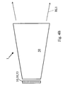
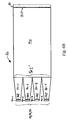
- the optics between the LED array and the light valve can redirect the rays within the cone of acceptance, increasing the efficiency of the device. This can be done either, by using collimation micro-lenses in front of the LED array as shown in Fig. 4A, or by using a pyramidal integration rod according to Fig. 4B. In both cases however, the active emitting surface is considerably smaller than the light valve surface. In other words, the efficiency of the illumination engine can be improved by using collimation optics, but at the cost of the light throughput of the LED array because of a diminution of the emitting surface.
- VCSEL Vertical cavity surface emitting lasers
- the intermediate optics i. e. the integration rod, is only used as light distribution uniformiser and has no collimation functionality.
- the integration rod also eliminates any coherent property of the VCSEL, i. e. speckle.
- Laser diodes have astigmatic emission, i.e. they do not need to be collimated in one axis (like VCSELs), but require collimation in the other axis. Asymmetric light pipes are therefore used.
- Figure 5 illustrates the architecture of a three-colour-path transmissive projector based on solid state light sources either LED array of VCSEL array and/or RCLED array.
- the imaging optics light valve and projection lens can be the same as those of a high-pressure lamp projector. However, the illumination engine is simplified and more compact, no fly-eye lens, no relay lenses are involved.
- the architecture of a hybrid projector, using high-pressure lamp for the green and blue channels and a solid state light source for the red channel, is schematically shown in Fig. 6.
- the goal of this configuration is to boosts the throughput of the red channel, which is relatively weak in standard HP lamp projectors (limitation due to the emission spectrum of high-pressure lamps). It should be noted that the more efficient visible solid state light source are available in the red.
- Solid state light sources can also be used in sequential colour projectors.
- the advantage over HP lamp sequential projectors is that colour management can be done directly at the source level, i. e. no colour filter for colour separation is needed.
- the colour selection is made electronically by switching on and off the different light sources.
- Very compact architectures can be achieved when using back-lighting illumination light pipes.
- the illumination light pipes have a similar design to those used for the back-lighting of T-LCD displays, typically used in laptops an cell phones.
- the light is guided inside the light pipe by total internal reflection and is selectively out-coupled from the light pipe by scattering zones placed along the light pipe surface.
- These compact projectors can be embedded into portable devices such as UMTS cell phones, camcorders, palmtops, or the like.
- Figs. 6, 7 and 8 What distinguish configurations of Figs. 6, 7 and 8 is the place available for the sources, i. e. for the emission surface, and therefore the resulting lumen throughput of the projector.
- the extremely reduced space available for the sources in Fig. 8 configurations implies the use of a highly efficient light sources, like VCSEL arrays and/or RCLED arrays.
- Configurations based on reflective light valves can also be built around solid state light sources. Nevertheless, the integration rod cannot be placed in close contact with the light valve, as the light should escape through the projection lens. In other words, some kind of beam splitter is needed in front of the light valve. The uniform distribution of light coming out of the integration rod has to be projected by some relay optics on the light valve. Basically all the standard reflective projector configurations based on integration rods can be adapted in order to use solid state light sources.
- One Aspect of the present invention and its embodiments is to solve the problem of finding a configuration which maximizes the illumination of a surface using an array of LEDs. Moreover, the illumination of the surface needs to be uniform and the direction of the rays kept within a limited aperture.
- the aperture or the angle of acceptance is determined by the numerical aperture of the imaging optics. The difficulty of the task comes from the fact that the angle of acceptance is generally small when compared to the large angular emission of the LEDs, having e.g. typically a Lambertian distribution.
- An illuminated surface may be, for example, the probe plane of a microscope, or the light valve plane of a projector.
- the imaging optics are in these cases the microscope objective or the projector objective.
- the constant improvement of the lumen output of light emitting diodes or LEDs make them natural candidates to be used as illumination light sources for automotive and building lighting.
- Other application like microscopy and projection display are more demanding as the surface to illuminate is relatively small, it has to be illuminated uniformly and within the angle of acceptance or aperture of the optics.
- the light source may either be formed by a single LED, or preferably by an LED array when the required brightness is high.
- LED arrays For LED arrays, it has been proposed to achieve the light collection using light pipes or fibers.
- the uniformity is usually achieved using an integration rod.
- an imaging optics In order to collimate the light within the aperture of the optics, an imaging optics is used to image the exit surface of the rod onto the plane to illuminate.
- Our inventive proposal consists of a simpler - therefore cheaper - and more energy efficient approach, as the pyramid light pipes fulfill three functions of light collection, light integration, and light collimation.
- the proposed approach minimizes the optical losses, lowers the manufacturing costs, and simplifies the device assembly.
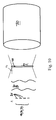
- the problem which is illustrated in Fig. 10, consists of finding a configuration which maximizes the illumination of a surface using an solid state light sources or array 33 of LEDs 31. Moreover the illumination has to be uniform and the direction of the rays kept within a limited aperture.
- the illuminated surface S 2 may be, for example, the probe plane of a microscope, or the plane of a light valve 40 of a projector.
- the maximal aperture of the illumination rays is then defined by the numerical aperture of the microscope objective or the F-number of the projector objective 70.
- the collimation optics has to fulfil three roles : light collector, light uniformizer, light collimator. These functions can be fulfilled by the combination of different types of elements.
- the difficulty of the task stems inter alia from the non-directive radiation pattern emitted by the LEDs 31, which is e.g. typically a Lambertian distribution. This light needs to be redirected onto the limited surface to illuminate and within the limited aperture of the optics.
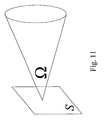
- the maximal useful étendue E 2 is defined by the surface S 2 to illuminate and the solid angle ⁇ 2 . For instance, if for the étendue E 1 of the source the relation E 1 >E 2 holds, then part of the light is lost.
- the solid angle ⁇ 2 is function of the aperture of the optics and is given by the equation where ⁇ 2 is the half angle of the cone of aperture.
- the étendue E 1 of the LED array is defined as where S 11 is the emission surface of each individual LED, N is the number of LEDs in the array, and 2 ⁇ is the solid angle of the hemisphere corresponding to the Lambertian emission.
- the étendue theorem states that the étendue along an optical system cannot be reduced. Therefore, in order to achieve an optical system with a 100 % collimation efficiency, the emission surface S, of the LED array cannot exceed S 1max as is shown by the following relations
- the problem is analysed by looking at what is the emitted cone or half-angle ⁇ 1 at the surface S 1 which is within the aperture of the optics or half-angle ⁇ 2 at the surface S 1 .
- the luminous flux W 2 reaching the surface S 2 within the aperture ⁇ 2 is proportional to the emission surface S 1 of the source and to the collimation efficiency ⁇ c , W 2 ⁇ c ⁇ S 1 .
- the working principle of a pyramidal integration rod or PIR is illustrated in Fig. 5.
- the PIR has an entry surface S', an exit surface S", and length L.
- the PIR can be an empty tube whose internal faces are mirrors, or a plain transparent material - e.g. mineral glass, plastic or the like - of index n.
- TIR total internal reflection
- the angle with respect to the PIR surfaces normal is smaller at the exit of the pipe than at its entrance.
- ⁇ ' is the solid angle of the ray before the PIR
- ⁇ " is the solid angle of the ray after the PIR.
- S">S' and ⁇ " ⁇ ' are fulfilled.
- the theoretical collimation efficiency ⁇ c is achieved for L ⁇ L c . Above the length L c the collimation efficiency is constant. L c is determined experimentally or by ray-tracing simulation, in a case by case basis.
- the PIR entry surface S' has to coincide with the LED emission surface S 1
- the PIR exit surface S" has to coincide with the surface S 2 to illuminate.
- the LED array is constituted by a set small emission surfaces S 11
- a micro PIR is placed in front of each LED. The light is then collected by a bigger PIR or integration rod.
- the three systems illustrated in Fig. 6 are all equivalent, given the length of the PIR is long enough to complete the collimation and the homogenisation.
- Main advantageous features of the present invention are the usage of a single optical element is used for light collection, light collimation, and light homogenisation.
- a single component from the light source (LED array) to the illuminated plane, the proposed approach minimizes the optical loses, lowers the manufacturing costs, and simplifies the device assembly.
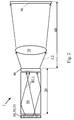
- Fig. 1 demonstrates by means of a schematical and cross-sectional side view a first preferred embodiment of the inventive illumination arrangement 1.
- the embodiment of Fig. 1 consists of a light source device 10, which is built-up by a solid state light source device 30.
- the solid state light source device 30 of the embodiment of Fig. 1 consists of an array 33 of light emitting diodes 31. Said array 33 is formed to have a light emitting area or light emitting aperture 30E from which primary illumination light L1 is emitted to reach an incidence aperture 501 of a light collecting, integrating and redirecting device 20 which may consist as in the example of Fig. 1 of a light integrating device 50 and of a light valve device 40, the former of which is in this case formed as an integration or integrator rod 50 of a solid bulk material, for instance glass, plastic, or the like.
- Rays of primary illumination light L1 entering said integrator rod 50 via said light incidence aperture 50I are first of all refracted according to the Snell's law of refraction and according to a refractive index of the material of the integrator rod 50 being larger than the refraction index of the gap material of the gap G between said integrator rod 50 and the light source device 10.
- a refractive index of the material of the integrator rod 50 being larger than the refraction index of the gap material of the gap G between said integrator rod 50 and the light source device 10.
- each of said received and multiply reflected rays of light of the primary illumination light L1 exits from the integrator rod 50 via output aperture 50E and then enters the light valve 40 being situated in direct proximity to the light output aperture 50E.
- the light distribution in the second gap G' between the integrator rod 50 and the light valve 40 is more uniform than the light distribution at the first gap G between the light source device and the integrator rod 50.
- the respective rays of light After receiving the redirected primary illumination light RL1 the respective rays of light are allowed to pass through the light valve 40 in a controllable manner and they leave the light valve 40 as secondary illumination light L2 to enter certain projection optics 70, shown in Fig. 2, and then entering a display screen 80.
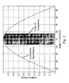
- the gap G between the light source device 10 and the integrator rod 50 which is shown in Figs. 1 and 2 is of particular importance as even in the case of an array of light emitting diodes each of said diodes 31 only has a minor directive emission capability because the light distribution or energy distribution of emitting light waves obeys a Lambertian distribution as shown in Fig. 3.
- Fig 3 demonstrates this Lambertian distribution as a graph demonstrating the relative energy of emitted light for a light emitting diode 31 as a function of the emission angle. From the distribution of Fig. 3 it can be derived, that it is necessary to keep the gap width of the gap G between the light source device 10 and the integrator rod 50 as narrow as possible to increase the integral or the amount of primary illumination light L1 entering the area of incidence or incidence aperture 501.
- the cones of acceptance of the integrator rod 50 and the displaying optics 70 may be different. Therefore, it could be necessary to adapt said cones of acceptance.
- This can be done alternatively by employing fly-eye-optics as shown in Fig. 4A or more preferably by using an integrator rod 50, having a pyramidal cross-section as shown in Fig. 4B.
- Figs. 5 to 9 demonstrate different possibilities of combining solid state light source devices 30 of different colours to obtain a multi-colour illumination arrangement for a multi-colour projection system.
- Fig. 5 three different coloured solid state light source devices 30 having e. g. light emitting diode arrays 33 are given, each of said solid state light source devices 30and therefore each of said light emitting diode arrays 33 being associated with an integrator rod 50 interposed between said solid state light source device 30 and a light valve arrangement 40, so that for each of said light source devices 30 of different colours an arrangement similar to that shown in Fig. 1 is given.
- a light mixing device 55 or colour cube 55 common for each of said three arrangements is given being capable of receiving the respective secondary illumination light L2, to mix them up, and to allow them to pass over to the projection optics 70.
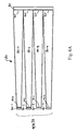
- Fig. 6A to 6C show different embodiments of the light collecting, integrating and redirecting unit or device 20 in the form of different integrator rod arrangements each of which being adapted for an array 33 of LEDs 31 or 31-1 to 31-4 as a light source device 10 and each of which being optically coupled to a light valve device 40.
- the light collecting, integrating and redirecting unit or device 20 is formed as a plurality of more or less similar or identical separated and parallely arranged single pyramidal integrator rods 50-1 to 50-4 each of which being uniquely assigned and coupled with its respective light entrance section 501 to a given LED 31-1 to 31-4, respectively.
- the light entrances 501 are in each case smaller than the respective light output sections 500 which are optically coupled to the light entrance section 401 of a common light valve device 40.
- Fig. 6B the more or less similar or identical separated and parallely arranged single pyramidal integrator rods 50-1 to 50-4 are optically coupled instead to the light entrance section 501' of a common and integrator rod 50 the light exit 500 of which being optically coupled to the light entrance section 401 of a common light valve device 40.
- the common integrator rod 50 of the embodiment of fig. 6B has a uniform cross section, whereas the cross section of common integrator rod 50 of the embodiment of Fig. 6C is non-uniform and the respective integrator rod 50 is formed pyramidal.
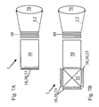
- Figs. 7A and 7B demonstrate two different arrangements for realizing multiple colour illumination arrangements for multiple colour projection systems which differ from the embodiment of Fig. 5.
- a solid state light source device 30 is employed as said light source device 10 which has a LED-array 33, the members of which, i. e. the distinct light emitting diodes 31, possessing different spectral emission ranges, i. e. different colours.
- each of said single solid state light source devices 30 is directed to the light mixing device 55 which after mixing directs the output light to the integrator rod 50 to obtain a secondary illumination light L2 at the gap G' between the light valve 40 and the integrator rod 50 having a uniform illumination and colour distribution.
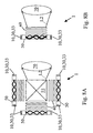
- Figs. 8A and 8B demonstrate further examples of multiple colour illumination devices.
- illumination light pipes 50 are used for redirecting and making uniform received amounts of primary illumination light L1.
- the incidence apertures 501 and output apertures 50E of the embodiments of Figs. 8A and 8B are perpendicular to each other. Therefore, primary illumination light L1 emitted by solid state light source devices 30 of the embodiments of Fig. 8A and 8B enters the associated illumination light pipes 50 at their base faces, whereas the redirected primary illumination light RL1 exits from said illumination light pipes 50 at side faces thereof.
- FIG. 8A A difference between the embodiments of Figs. 8A and 8B is that for obtaining a multi-colour arrangement in Fig. 8A a plurality of single coloured solid state light source devices 30 or LED-arrays 33 is necessary, whereas in the embodiment of Fig. 8B multiple coloured solid state light source devices 30 or LED-arrays 33 are provided.
- the embodiment of Fig. 9 demonstrates an application of the embodiment of Fig. 7B, having intermediate optics 81, 82 for adapting the cones of acceptance between the integrator rod 50 and the light valve 40.
- the intermediate optics 81, 82 consists of a lens arrangement 81 and a polarization beam splitter 82 which in combination with each other transforms or maps the cone of acceptance of the integrator rod 50, i. e. the geometry of the redirected primary illumination light RL1, to the cone of acceptance of the light valve 40, which is in the embodiment of Fig. 9 a reflective light valve 40 which allows the passage of secondary illumination light L2 to the projection optics 70 upon reflection at the interface of light valve 40.
Landscapes
- Physics & Mathematics (AREA)
- General Physics & Mathematics (AREA)
- Optics & Photonics (AREA)
- Engineering & Computer Science (AREA)
- Multimedia (AREA)
- Signal Processing (AREA)
- Projection Apparatus (AREA)
Priority Applications (10)
| Application Number | Priority Date | Filing Date | Title |
|---|---|---|---|
| EP02024962A EP1418765A1 (fr) | 2002-11-07 | 2002-11-07 | Dispositif d'éclairage pour un système de projection |
| DE60337026T DE60337026D1 (de) | 2002-11-07 | 2003-11-06 | Beleuchtungsanordnung für eine projektionsvorrichtung |
| CN2003801082579A CN1736111B (zh) | 2002-11-07 | 2003-11-06 | 投影系统用的照明装置 |
| AU2003288007A AU2003288007A1 (en) | 2002-11-07 | 2003-11-06 | Illumination arrangement for a projection system |
| KR1020057008138A KR20060023946A (ko) | 2002-11-07 | 2003-11-06 | 투사 시스템용 조사 배열체 |
| US10/534,237 US7929214B2 (en) | 2002-11-07 | 2003-11-06 | Illumination arrangement for a projection system |
| PCT/EP2003/012417 WO2004043076A2 (fr) | 2002-11-07 | 2003-11-06 | Dispositif d'eclairage pour systeme de projection |
| JP2005502111A JP2006505830A (ja) | 2002-11-07 | 2003-11-06 | プロジェクタシステムのための照明装置 |
| EP03779859A EP1561349B1 (fr) | 2002-11-07 | 2003-11-06 | Dispositif d'eclairage pour systeme de projection |
| US12/905,695 US8351122B2 (en) | 2002-11-07 | 2010-10-15 | Illumination arrangement for a projection system |
Applications Claiming Priority (1)
| Application Number | Priority Date | Filing Date | Title |
|---|---|---|---|
| EP02024962A EP1418765A1 (fr) | 2002-11-07 | 2002-11-07 | Dispositif d'éclairage pour un système de projection |
Publications (1)
| Publication Number | Publication Date |
|---|---|
| EP1418765A1 true EP1418765A1 (fr) | 2004-05-12 |
Family
ID=32103918
Family Applications (1)
| Application Number | Title | Priority Date | Filing Date |
|---|---|---|---|
| EP02024962A Ceased EP1418765A1 (fr) | 2002-11-07 | 2002-11-07 | Dispositif d'éclairage pour un système de projection |
Country Status (1)
| Country | Link |
|---|---|
| EP (1) | EP1418765A1 (fr) |
Cited By (12)
| Publication number | Priority date | Publication date | Assignee | Title |
|---|---|---|---|---|
| WO2005115013A1 (fr) * | 2004-05-14 | 2005-12-01 | 3M Innovative Properties Company | Système d’illumination avec des chemins optiques séparés pour différents canaux de couleur |
| WO2006022620A1 (fr) * | 2004-07-22 | 2006-03-02 | Thomson Licensing | Geometrie discrete a haute frequence de commutation pour micro-affichage a imageur unique |
| JP2007065080A (ja) * | 2005-08-29 | 2007-03-15 | Sony Corp | 空間光変調光学装置とこれを用いた虚像光学装置及び投射型画像表示装置 |
| DE102005049715B3 (de) * | 2005-10-18 | 2007-05-10 | Carl Zeiss Jena Gmbh | Anordnung zur homogenen Ausleuchtung einer Ebene |
| DE102006031076A1 (de) * | 2006-03-17 | 2007-09-20 | Osram Opto Semiconductors Gmbh | Optisches Projektionsgerät |
| FR2898958A1 (fr) * | 2006-03-21 | 2007-09-28 | Regenerer Sarl | Dispositif de production de lumiere |
| WO2007107650A3 (fr) * | 2006-03-21 | 2007-11-08 | Regenerer | Dispositif de production de lumiere ambiante isotrope |
| WO2008017286A1 (fr) * | 2006-08-09 | 2008-02-14 | Jenoptik Laser, Optik, Systeme Gmbh | Dispositif optique de pompage de lasers solides |
| WO2009024949A1 (fr) * | 2007-08-23 | 2009-02-26 | Koninklijke Philips Electronics N.V. | Source de lumière pour un projecteur |
| EP1920289A4 (fr) * | 2005-07-29 | 2009-10-28 | Optical Res Associates | Melangeurs ondules destines a l'uniformite et au melange de couleurs |
| EP2503378A3 (fr) * | 2011-03-25 | 2012-11-14 | MIN AIK Technology Co., Ltd. | Procédé de mélange de lumière de couleur, dispositif de mélange de lumière de couleur et système de projection de petite dimension ayant un tel dispositif de mélange de lumière de couleur |
| CN106886086A (zh) * | 2008-10-27 | 2017-06-23 | 通快光子学公司 | 激光束交织 |
Citations (10)
| Publication number | Priority date | Publication date | Assignee | Title |
|---|---|---|---|---|
| EP0322070A1 (fr) * | 1987-12-23 | 1989-06-28 | Koninklijke Philips Electronics N.V. | Système de projection à modulateur de lumière avec illumination non formatrice d'image |
| JPH10123512A (ja) * | 1996-08-28 | 1998-05-15 | Sanyo Electric Co Ltd | 液晶表示装置用光源及びそれを用いたカラー液晶表示装置 |
| EP1003064A1 (fr) * | 1998-06-04 | 2000-05-24 | Seiko Epson Corporation | Dispositif d'eclairage, dispositif optique et affichage a cristaux liquides |
| EP1024669A1 (fr) * | 1999-01-29 | 2000-08-02 | Agilent Technologies Inc | Source lumineuse avec des diodes électroluminescentes pour un projecteur d'images |
| US6220714B1 (en) * | 1997-09-22 | 2001-04-24 | Sony Corporation | Image display apparatus |
| WO2001043113A1 (fr) * | 1999-12-09 | 2001-06-14 | Koninklijke Philips Electronics N.V. | Systemes d'affichage incorporant une source de lumiere de diode electroluminescente |
| US6318863B1 (en) * | 1999-01-21 | 2001-11-20 | Industrial Technology Research Institute | Illumination device and image projection apparatus including the same |
| US20010048560A1 (en) * | 2000-05-31 | 2001-12-06 | Yasuyuki Sugano | Display apparatus |
| WO2002003130A1 (fr) * | 2000-06-30 | 2002-01-10 | Neurok, Llc | Afficheur couleur a cristaux liquides |
| JP2002133932A (ja) * | 2000-10-20 | 2002-05-10 | Casio Comput Co Ltd | 光源素子 |
-
2002
- 2002-11-07 EP EP02024962A patent/EP1418765A1/fr not_active Ceased
Patent Citations (10)
| Publication number | Priority date | Publication date | Assignee | Title |
|---|---|---|---|---|
| EP0322070A1 (fr) * | 1987-12-23 | 1989-06-28 | Koninklijke Philips Electronics N.V. | Système de projection à modulateur de lumière avec illumination non formatrice d'image |
| JPH10123512A (ja) * | 1996-08-28 | 1998-05-15 | Sanyo Electric Co Ltd | 液晶表示装置用光源及びそれを用いたカラー液晶表示装置 |
| US6220714B1 (en) * | 1997-09-22 | 2001-04-24 | Sony Corporation | Image display apparatus |
| EP1003064A1 (fr) * | 1998-06-04 | 2000-05-24 | Seiko Epson Corporation | Dispositif d'eclairage, dispositif optique et affichage a cristaux liquides |
| US6318863B1 (en) * | 1999-01-21 | 2001-11-20 | Industrial Technology Research Institute | Illumination device and image projection apparatus including the same |
| EP1024669A1 (fr) * | 1999-01-29 | 2000-08-02 | Agilent Technologies Inc | Source lumineuse avec des diodes électroluminescentes pour un projecteur d'images |
| WO2001043113A1 (fr) * | 1999-12-09 | 2001-06-14 | Koninklijke Philips Electronics N.V. | Systemes d'affichage incorporant une source de lumiere de diode electroluminescente |
| US20010048560A1 (en) * | 2000-05-31 | 2001-12-06 | Yasuyuki Sugano | Display apparatus |
| WO2002003130A1 (fr) * | 2000-06-30 | 2002-01-10 | Neurok, Llc | Afficheur couleur a cristaux liquides |
| JP2002133932A (ja) * | 2000-10-20 | 2002-05-10 | Casio Comput Co Ltd | 光源素子 |
Non-Patent Citations (2)
| Title |
|---|
| PATENT ABSTRACTS OF JAPAN vol. 1998, no. 10 31 August 1998 (1998-08-31) * |
| PATENT ABSTRACTS OF JAPAN vol. 2002, no. 09 4 September 2002 (2002-09-04) * |
Cited By (20)
| Publication number | Priority date | Publication date | Assignee | Title |
|---|---|---|---|---|
| US7222968B2 (en) | 2004-05-14 | 2007-05-29 | 3M Innovative Properties Company | Illumination system with separate optical paths for different color channels |
| WO2005115013A1 (fr) * | 2004-05-14 | 2005-12-01 | 3M Innovative Properties Company | Système d’illumination avec des chemins optiques séparés pour différents canaux de couleur |
| CN1954618B (zh) * | 2004-05-14 | 2010-05-05 | 3M创新有限公司 | 不同的颜色通道具有分离光路的照明系统 |
| WO2006022620A1 (fr) * | 2004-07-22 | 2006-03-02 | Thomson Licensing | Geometrie discrete a haute frequence de commutation pour micro-affichage a imageur unique |
| CN100588265C (zh) * | 2004-07-22 | 2010-02-03 | 汤姆森许可公司 | 用于单个成像器微显示的离散的高开关速度的照明几何结构 |
| EP1920289A4 (fr) * | 2005-07-29 | 2009-10-28 | Optical Res Associates | Melangeurs ondules destines a l'uniformite et au melange de couleurs |
| JP2007065080A (ja) * | 2005-08-29 | 2007-03-15 | Sony Corp | 空間光変調光学装置とこれを用いた虚像光学装置及び投射型画像表示装置 |
| DE102005049715B3 (de) * | 2005-10-18 | 2007-05-10 | Carl Zeiss Jena Gmbh | Anordnung zur homogenen Ausleuchtung einer Ebene |
| DE102006031076A1 (de) * | 2006-03-17 | 2007-09-20 | Osram Opto Semiconductors Gmbh | Optisches Projektionsgerät |
| US7976200B2 (en) | 2006-03-17 | 2011-07-12 | Osram Opto Semiconductors Gmbh | Optical projection device |
| WO2007107650A3 (fr) * | 2006-03-21 | 2007-11-08 | Regenerer | Dispositif de production de lumiere ambiante isotrope |
| FR2898958A1 (fr) * | 2006-03-21 | 2007-09-28 | Regenerer Sarl | Dispositif de production de lumiere |
| US8011800B2 (en) | 2006-03-21 | 2011-09-06 | Regenerer | Device for producing isotropic ambient light |
| WO2008017286A1 (fr) * | 2006-08-09 | 2008-02-14 | Jenoptik Laser, Optik, Systeme Gmbh | Dispositif optique de pompage de lasers solides |
| WO2009024949A1 (fr) * | 2007-08-23 | 2009-02-26 | Koninklijke Philips Electronics N.V. | Source de lumière pour un projecteur |
| US7940341B2 (en) | 2007-08-23 | 2011-05-10 | Philips Lumileds Lighting Company | Light source for a projector |
| CN106886086A (zh) * | 2008-10-27 | 2017-06-23 | 通快光子学公司 | 激光束交织 |
| CN106886086B (zh) * | 2008-10-27 | 2021-06-04 | 通快光子学公司 | 激光束交织 |
| EP2503378A3 (fr) * | 2011-03-25 | 2012-11-14 | MIN AIK Technology Co., Ltd. | Procédé de mélange de lumière de couleur, dispositif de mélange de lumière de couleur et système de projection de petite dimension ayant un tel dispositif de mélange de lumière de couleur |
| US8998418B2 (en) | 2011-03-25 | 2015-04-07 | Min Aik Technology Co., Ltd | Color light mixing method, color light mixing device and small-sized projecting system having such color light mixing device |
Similar Documents
| Publication | Publication Date | Title |
|---|---|---|
| US7929214B2 (en) | Illumination arrangement for a projection system | |
| US7889430B2 (en) | LED-based high efficiency illumination systems for use in projection systems | |
| US7510316B2 (en) | Ultra compact illumination system for display systems | |
| JP3218401U (ja) | 光学照明装置 | |
| US7740375B2 (en) | High brightness illumination device with incoherent solid state light source | |
| US6547400B1 (en) | Light source device, optical device, and liquid-crystal display device | |
| KR101427503B1 (ko) | 면 형상 광원 장치 및 액정 표시 장치 | |
| US9010938B2 (en) | Projector with multiple different types of illumination devices | |
| US20080030974A1 (en) | LED-Based Illumination System | |
| TW200527076A (en) | Lighting system and back-light device of using this lighting system | |
| KR20180048803A (ko) | 대면적 광원 및 대면적 조명기구 | |
| JP2010040296A (ja) | アレイ光源用光学素子及びそれを用いた発光装置 | |
| US20090161076A1 (en) | Projection apparatus | |
| JP2012209036A (ja) | 光源装置 | |
| US20060139575A1 (en) | Optical collection and distribution system and method | |
| JP2008281829A (ja) | 照明光学系 | |
| KR20090085134A (ko) | 프로젝션 디스플레이 디바이스 및 이미지 광 생성 시스템 | |
| CN221056819U (zh) | 投影光机和ar显示装置 | |
| US20080239253A1 (en) | Optical element and projection system using the same | |
| GB2457296A (en) | Optical device e.g. radiant-power-transferring light engine | |
| EP2049927A2 (fr) | Dispositif photoémetteur | |
| US20050226585A1 (en) | Compact polarization conversion system for optical displays | |
| US20120327375A1 (en) | Illumination device and projection display device using the same | |
| CN118859541A (zh) | 一种分光器件及光学系统 |
Legal Events
| Date | Code | Title | Description |
|---|---|---|---|
| PUAI | Public reference made under article 153(3) epc to a published international application that has entered the european phase |
Free format text: ORIGINAL CODE: 0009012 |
|
| AK | Designated contracting states |
Kind code of ref document: A1 Designated state(s): AT BE BG CH CY CZ DE DK EE ES FI FR GB GR IE IT LI LU MC NL PT SE SK TR |
|
| AX | Request for extension of the european patent |
Extension state: AL LT LV MK RO SI |
|
| 17P | Request for examination filed |
Effective date: 20041110 |
|
| AKX | Designation fees paid |
Designated state(s): BE DE FR GB NL |
|
| RAP1 | Party data changed (applicant data changed or rights of an application transferred) |
Owner name: SONY DEUTSCHLAND GMBH |
|
| RAP1 | Party data changed (applicant data changed or rights of an application transferred) |
Owner name: SONY DEUTSCHLAND GMBH |
|
| STAA | Information on the status of an ep patent application or granted ep patent |
Free format text: STATUS: THE APPLICATION HAS BEEN REFUSED |
|
| 18R | Application refused |
Effective date: 20071228 |