EP1419010B1 - Broyeur a rouleaux et procede pour broyer des materiaux comportant des elements magnetisables - Google Patents
Broyeur a rouleaux et procede pour broyer des materiaux comportant des elements magnetisables Download PDFInfo
- Publication number
- EP1419010B1 EP1419010B1 EP02764781A EP02764781A EP1419010B1 EP 1419010 B1 EP1419010 B1 EP 1419010B1 EP 02764781 A EP02764781 A EP 02764781A EP 02764781 A EP02764781 A EP 02764781A EP 1419010 B1 EP1419010 B1 EP 1419010B1
- Authority
- EP
- European Patent Office
- Prior art keywords
- roller
- grinding
- electromagnetic device
- particles
- air
- Prior art date
- Legal status (The legal status is an assumption and is not a legal conclusion. Google has not performed a legal analysis and makes no representation as to the accuracy of the status listed.)
- Expired - Lifetime
Links
- 238000000227 grinding Methods 0.000 title claims abstract description 106
- 238000000034 method Methods 0.000 title claims abstract description 20
- 239000000463 material Substances 0.000 title claims abstract description 19
- XEEYBQQBJWHFJM-UHFFFAOYSA-N Iron Chemical compound [Fe] XEEYBQQBJWHFJM-UHFFFAOYSA-N 0.000 claims abstract description 76
- 239000002245 particle Substances 0.000 claims abstract description 48
- 229910052742 iron Inorganic materials 0.000 claims abstract description 34
- 238000003801 milling Methods 0.000 claims abstract description 13
- 239000002893 slag Substances 0.000 claims abstract description 10
- 239000000470 constituent Substances 0.000 claims abstract 9
- 238000000926 separation method Methods 0.000 claims description 13
- 238000005096 rolling process Methods 0.000 claims description 7
- 230000001105 regulatory effect Effects 0.000 claims description 3
- 230000005484 gravity Effects 0.000 claims description 2
- 239000011362 coarse particle Substances 0.000 claims 2
- 238000010276 construction Methods 0.000 claims 2
- 238000007599 discharging Methods 0.000 claims 1
- 230000008569 process Effects 0.000 description 6
- 239000006148 magnetic separator Substances 0.000 description 5
- 239000000126 substance Substances 0.000 description 5
- 239000004568 cement Substances 0.000 description 4
- 230000008021 deposition Effects 0.000 description 4
- 239000002184 metal Substances 0.000 description 4
- 229910052751 metal Inorganic materials 0.000 description 4
- 230000008901 benefit Effects 0.000 description 3
- 230000000694 effects Effects 0.000 description 3
- 230000015572 biosynthetic process Effects 0.000 description 2
- 238000000605 extraction Methods 0.000 description 2
- 229910052602 gypsum Inorganic materials 0.000 description 2
- 239000010440 gypsum Substances 0.000 description 2
- 239000004615 ingredient Substances 0.000 description 2
- 239000002923 metal particle Substances 0.000 description 2
- 239000000203 mixture Substances 0.000 description 2
- CWYNVVGOOAEACU-UHFFFAOYSA-N Fe2+ Chemical compound [Fe+2] CWYNVVGOOAEACU-UHFFFAOYSA-N 0.000 description 1
- 238000009825 accumulation Methods 0.000 description 1
- 230000001464 adherent effect Effects 0.000 description 1
- 230000004888 barrier function Effects 0.000 description 1
- 230000008859 change Effects 0.000 description 1
- 230000001276 controlling effect Effects 0.000 description 1
- 238000009499 grossing Methods 0.000 description 1
- 230000002452 interceptive effect Effects 0.000 description 1
- 239000000696 magnetic material Substances 0.000 description 1
- 238000004519 manufacturing process Methods 0.000 description 1
- 230000008439 repair process Effects 0.000 description 1
- 238000005488 sandblasting Methods 0.000 description 1
- 238000011144 upstream manufacturing Methods 0.000 description 1
- 230000000007 visual effect Effects 0.000 description 1
- 238000005303 weighing Methods 0.000 description 1
Images


Classifications
-
- B—PERFORMING OPERATIONS; TRANSPORTING
- B02—CRUSHING, PULVERISING, OR DISINTEGRATING; PREPARATORY TREATMENT OF GRAIN FOR MILLING
- B02C—CRUSHING, PULVERISING, OR DISINTEGRATING IN GENERAL; MILLING GRAIN
- B02C15/00—Disintegrating by milling members in the form of rollers or balls co-operating with rings or discs
- B02C15/001—Air flow directing means positioned on the periphery of the horizontally rotating milling surface
-
- B—PERFORMING OPERATIONS; TRANSPORTING
- B02—CRUSHING, PULVERISING, OR DISINTEGRATING; PREPARATORY TREATMENT OF GRAIN FOR MILLING
- B02C—CRUSHING, PULVERISING, OR DISINTEGRATING IN GENERAL; MILLING GRAIN
- B02C15/00—Disintegrating by milling members in the form of rollers or balls co-operating with rings or discs
- B02C15/14—Edge runners, e.g. Chile mills
-
- B—PERFORMING OPERATIONS; TRANSPORTING
- B02—CRUSHING, PULVERISING, OR DISINTEGRATING; PREPARATORY TREATMENT OF GRAIN FOR MILLING
- B02B—PREPARING GRAIN FOR MILLING; REFINING GRANULAR FRUIT TO COMMERCIAL PRODUCTS BY WORKING THE SURFACE
- B02B3/00—Hulling; Husking; Decorticating; Polishing; Removing the awns; Degerming
- B02B3/04—Hulling; Husking; Decorticating; Polishing; Removing the awns; Degerming by means of rollers
-
- B—PERFORMING OPERATIONS; TRANSPORTING
- B02—CRUSHING, PULVERISING, OR DISINTEGRATING; PREPARATORY TREATMENT OF GRAIN FOR MILLING
- B02C—CRUSHING, PULVERISING, OR DISINTEGRATING IN GENERAL; MILLING GRAIN
- B02C15/00—Disintegrating by milling members in the form of rollers or balls co-operating with rings or discs
-
- B—PERFORMING OPERATIONS; TRANSPORTING
- B02—CRUSHING, PULVERISING, OR DISINTEGRATING; PREPARATORY TREATMENT OF GRAIN FOR MILLING
- B02C—CRUSHING, PULVERISING, OR DISINTEGRATING IN GENERAL; MILLING GRAIN
- B02C15/00—Disintegrating by milling members in the form of rollers or balls co-operating with rings or discs
- B02C15/004—Shape or construction of rollers or balls
- B02C15/005—Rollers or balls of composite construction
-
- B—PERFORMING OPERATIONS; TRANSPORTING
- B02—CRUSHING, PULVERISING, OR DISINTEGRATING; PREPARATORY TREATMENT OF GRAIN FOR MILLING
- B02C—CRUSHING, PULVERISING, OR DISINTEGRATING IN GENERAL; MILLING GRAIN
- B02C15/00—Disintegrating by milling members in the form of rollers or balls co-operating with rings or discs
- B02C15/12—Mills with at least two discs or rings and interposed balls or rollers mounted like ball or roller bearings
-
- B—PERFORMING OPERATIONS; TRANSPORTING
- B02—CRUSHING, PULVERISING, OR DISINTEGRATING; PREPARATORY TREATMENT OF GRAIN FOR MILLING
- B02C—CRUSHING, PULVERISING, OR DISINTEGRATING IN GENERAL; MILLING GRAIN
- B02C15/00—Disintegrating by milling members in the form of rollers or balls co-operating with rings or discs
- B02C2015/002—Disintegrating by milling members in the form of rollers or balls co-operating with rings or discs combined with a classifier
Definitions
- the invention relates to a roller mill according to the preamble of claim 1, in particular an air flow roller mill according to the preamble of claim 4, and a method for Milling of materials with magnetizable, in particular ferrous components according to the preamble of the claim 14th
- the invention is preferred for slag mills and for Grinding of granulated blastfurnace slag and for use in cement grinding plants suitable in which air flow roller mills for Milling of cement clinker, gypsum and blastfurnace slag used be (DE 39 21 986 C1).
- Blastfurnace slag is produced during iron production during the Blast furnace process and contains iron particles, which in Grinding process to a relatively high wear of the grinding process lead involved components.
- the feed material is present the crushing a magnetic separator, in particular an overband magnetic separator supplied. Be here However, only removed components that are free and not enclosed by slag. These ingredients arrive with the stuffing in the mill.
- the iron particles are digested during the milling process and accumulate because of their high specificity Weight and poor grindability on the Grinder bowl on. A removal takes place only if these enriched iron particles due to centrifugal force over the grinding bowl edge and the vane ring in the Ring channel and from here to the external circulation for the so-called "outside grotesque" get where they are about magnetic Separators are separated from the semolina.
- From CH-PS 103 265 is a method for crushing, Crushing or squeezing any substances known at which the elements between which the millbase of the treatment is subjected, with magnetic force against each other be pressed.
- Roller mills are described in which the magnetically generated between the grinding rollers Pressure to reduce bearing pressures and moving Should lead masses.
- magnetic substances in regrind should be the signs of wear on the grinding rollers after its formation automatically eliminated by it be that the magnetic components to the elevations be attracted and crushed, leaving a larger Wear as takes place in the wells.
- For separating magnetizable substances in the millbase is at least in addition a magnetizable separating roller before or after the Mahlspalt be arranged, which with one of the two Milling rollers cooperates.
- the invention has for its object to provide a roller mill, in particular an air flow roller mill, and a method which in a very simple and efficient way, without interrupting the grinding operation and maintaining the product quality removal of the iron components and other metal components from the material to be ground in the grinding room.
- a basic idea of the invention can be seen therein in the grinding room, especially in the grinding bed on the grinding bowl existing and open-minded during comminution magnetizable particles, in particular iron particles, with the help of at least one electromagnetic Device which is arranged in the grinding chamber to remove and by the extraction of these particles, which in particular can be done continuously, enriching this Avoid particles on the grinding bed.
- the electromagnetic device is a roller-like and rolling on the grinding bed device, which is designed such that the magnetizable, especially iron particles, the grinding bed at the surface adhere.
- a discharge device which with the roller-like electromagnetic device connected is and interacts with this, the isolated magnetizable components of the roll-like Device removed and discharged from the grinding chamber.
- the electromagnetic device can also above the grinding bed and with an adjustable gap between the shell of the cylindrical device and the Grinding bowl be arranged.
- roller mills which, for example, as overflow mills used and have no integrated classifier, can also be a grinding roller for electromagnetic separation be educated.
- iron particles hereinafter also other magnetizable particles be understood, the wear of Grinding rollers and grinding bowl reduced and the service life elevated.
- At least one electromagnetic To install equipment in air flow roller mills which at least one pair of rollers, usually two or also three pairs of rollers, have.
- a pair of rollers exists from a grinding roller, also called master roller, and out an auxiliary roll, also called slave roll or slave roller, which is upstream of the grinding roller and the grinding bed prepared, in particular uniformed and compacted, and, especially for hard and brittle materials, one optimized, vibration-free grinding guaranteed.
- At least one auxiliary roll to the electromagnetic Separation of magnetisable components, in particular iron particles to form from the grinding bed and to connect with a discharge device, with which removes these interfering components from the grinding chamber can be.
- the auxiliary roll a non-magnetic roll shell and inside a controllable Electromagnet, preferably with an iron core and electric coils, their shape and arrangement in order to build up an effective magnetic field over one adjusted predetermined range of the roll shell of the roll shape are.
- a controllable Electromagnet preferably with an iron core and electric coils, their shape and arrangement in order to build up an effective magnetic field over one adjusted predetermined range of the roll shell of the roll shape are.
- the power supply for the electric coils may expediently take place in the region of the roll axis. Furthermore can for controlling the electromagnet advantageously a Thyristor be provided.
- the discharge device for the removal of the electromagnetic Device deposited metal particles, in particular the iron particles, is expediently such formed so that the deposited particles continuously transported from the grinding room and for example over the vane ring in a arranged underneath Room can be transported.
- a discharge device which a scraper, a conveyor trough and a downpipe.
- the scraper may be formed strip-shaped and expediently at least over the width of the rolling Surface of the electromagnetic device, e.g. of Mantels an auxiliary roll, enough. Besides, it is for one trouble-free takeover of the particles expedient if the Scrapers parallel and with an adjustable distance to the Roll shell of the electromagnetically designed auxiliary roll is arranged.
- the scraper is detachable and / or height adjustable attached to the conveyor trough.
- the scraper and the conveyor trough one unity.
- the conveyor trough with defined arranged Scrapers are then advantageously fastened such that a height adjustment and a change of the gap between the wiper and the electromagnetic roller is possible.
- the scraper and / or the conveyor trough be attached to the mill housing.
- auxiliary roll with electromagnet, for example in the region of the oscillating lever or the roll axis, advantageous.
- the scraper and / or the conveyor trough then follow the movement of the auxiliary roll and be with this moved up and down on the grinding bed.
- the conveyor trough has expediently in the direction of Opening in the vane ring a slope, leaving the stripped Particles transported due to gravity be and, for example via a downpipe, which is arranged in an opening in the vane ring, in the annular channel or a space below the vane ring reach.
- a controllable Close the barrier For example, a weight-loaded pendulum flap be installed, which at a predeterminable load of accumulated particles in Direction ring is swung open.
- magnetisable in particular iron-containing components
- slags that provides in addition to an electromagnetic separation before the grinding process in a roller mill, in particular in an air flow roller mill, another electromagnetic deposition In the grinding room is carried out to the in the grinding process to extract digested, freely present particles and an accumulation of these particles on the grinding bowl to avoid.
- the electromagnetic deposition in Grinding chamber by means of a roller-shaped device, in particular an auxiliary roll performed.
- a roller-shaped device in particular an auxiliary roll performed.
- Mahlbettpreparierung can with at least one cylindrical, on the grinding bed rolling electromagnetic device, for example, an auxiliary roll, which with a controllable electromagnet is provided, an extraction the magnetizable particles, in particular the iron particles, take place from the grinding bed and the grinding chamber. It can a continuous deposition at the electromagnetic trained auxiliary roll performed particularly advantageous become.
- the deposited on the electromagnetically trained auxiliary roll Particles are then advantageously using a corresponding discharge device, stripped over the vane ring the annular channel of the air flow roller mill fed and along with the over the Mahlschüsselrand thrown, reaching into the annulus semolina from the Mill discharged and mechanically, especially with a Reciprocating bucket, for feeder, e.g. to a Weighing belt for the feed material, promoted.
- a Reciprocating bucket for feeder, e.g. to a Weighing belt for the feed material, promoted.
- another metal deposit in particular an electromagnetic separation, carried out.
- the grits are then usually with fed new feed of the air flow roller mill again.
- Electromagnet regulated by the speed signal of the auxiliary rollers become.
- the Advantages that essentially the existing component devices can be used. Because of the continuous Separation and discharge from the grinding chamber and the space below the grinding bowl is a total of one lesser outer orbit, and the plant for the reclaimed grits, also called reject plant, can be sized smaller. Furthermore are suitable the separated and discharged iron particles as a material for sandblasting. Another essential The advantage is the avoidance of signs of wear at the grinding rolls, auxiliary rolls and at the grinding track and the related repair costs, downtime etc.
- Fig. 1 shows a LOESCHE air flow roller mill 2, which is particularly It is predestined for cement and granulated blastfurnace grinding and with two pairs of rollers 3, 15 is provided.
- Fig. 1 two grinding rollers 3, but only an auxiliary roller 15 shown. From Fig. 2, however, go the two pairs of rollers, each consisting of a Grinding roller (master roller) 3 and an auxiliary roller (slave roller) 15 exist.
- the grinding rollers 3 and auxiliary rollers 15 roll on a grinding bed starting from the feed material on a grinding track of a rotating grinding bowl 4 is formed.
- the grinding bowl 4, which is rotated by a drive 8 in rotation, is surrounded by a vane ring 6, via which a Gas stream, in particular air, from a ring line 7 in the Grinding chamber 5 flows.
- the feed for example blast furnace slag or a mixture of cement clinker, gypsum and Slag, via metering devices, becomes a magnetic separator and a task device (not shown) abandoned the air flow roller mill, arrives the grinding bowl 4 and is pressed between the resilient Grinding rollers 3 and the grinding bowl 4 crushed.
- a feed channel 17 and the annular channel 7 through the Guide vane 16 in the grinding chamber 5 incoming air conveys the mixture of fine and coarse material into a viewing area 13 and in the range of a classifier 9. Grobgut is rejected and falls back to the grinding bowl 4, while Fine material is discharged via a fine material discharge 14.
- Fig. 1 are also the mill housing 12, the rocker arm 10 of the two grinding rollers 3 and a hydraulic cylinder device 11 at the left grinding roller 3, which shows the effect resilient contact pressure of the grinding rollers 3.
- the auxiliary rollers 15 have in the present embodiment 1 and 2, a smaller diameter than the grinding rollers 3 and are in contrast to the grinding rollers 3 not kraftbeaufschlagt, but lie with their own weight on the grinding bed, with a pure rolling motion or one superimposed by a targeted sliding movement Rolling motion occurs.
- Each auxiliary roll prepares 15 the grinding bed for - in the direction of rotation of the roller bowl 5 seen behind the auxiliary roller 15 arranged grinding roller 3, which performs the crushing of the ground material.
- arrangement and effect of auxiliary rollers is to the German Patent 39 21 986 referenced.
- Fig. 2 shows that the auxiliary roller 15 as the grinding rollers. 3 are conical and their width about the Mahlbahnbreite equivalent.
- At least one auxiliary roll 15 is for electromagnetic Separation of magnetisable fractions, in particular iron fractions, formed from the grinding stock to be comminuted, an enrichment of these ingredients on the grinding bowl 4 and concomitant wear of the grinder to avoid.
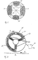
- Fig. 3 shows a trained for electromagnetic separation Auxiliary roll 15 in cross section.
- Arrow A gives the Direction of rotation of the auxiliary roller 15 and arrow B the direction of rotating grinding bowl 4 on.
- the ground material to be comminuted or the grinding bed is not shown.
- the auxiliary roller 15 has a roll shell 23 made of a non-magnetic material on and inside is iron core 21 and provided with electric coils 22.
- the iron core 21 is the conically shaped roll shell 23 of the auxiliary roll 15 adapted and reaches - seen in cross section - about about two thirds of the lateral surface, so that the to be removed Metal, in particular iron particles, from the grinding bed on the Grinding bowl 4 can be picked up and rotating Roll shell 23 adhering, up to a discharge 30 are transported.
- the discharge device 30 goes also shown in FIG. 4.
- a scraper 31 and a conveyor trough 32 is shown very schematically.
- the electromagnetic device 20 in the interior of the auxiliary roll 15 has three electric coils 22 which in a Angular distance of about 120 ° are arranged radially and with the iron core 21 form the stationary electromagnet, through the iron particles on the grinding bowl be tightened and on the rotating roll shell 23 adherent, up to a magnetic-free area and the here arranged discharge device 30 arrive.
- Fig. 4 From Fig. 4 go the conical iron core 21 near the Roll shell 23 of the auxiliary roll 15 and the arrangement of the scraper 31 on the conveyor trough 30 out.
- the scraper 31 is strip-shaped and parallel and with a small distance to the roll shell 23 on the conveyor trough 32 attached.
- the conveyor trough 32 is at a slight slope in the direction Mill housing 12 and Leitschaufelkranz 7 arranged and opens into a downpipe 33.
- the downpipe is in one Opening 35 of the vane ring 7 is arranged and extends up to the annular channel 7.
- the attachment of the downpipe 33rd can via fasteners 36 in the region of adjacent Guide vanes of the vane ring 6 or on the mill housing 12 done.
- the drop tube 33 is at the lower end provided with a closure flap 34, which as a weight-loaded Swing flap is formed.
- the deposited on the auxiliary roll 15 magnetized particles and in particular iron particles are only in the range held the iron core 21 and then pass through the Scraper 31 in the conveyor trough 32, then in the downpipe 33 and in the annular channel 7. In the annular channel 7 and a Space below the grinding chamber, the coarse material particles collect or grits that neither from the grinding rollers 3 for Crushing were detected, still in the air stream to reformer 9 have arrived.
Landscapes
- Engineering & Computer Science (AREA)
- Food Science & Technology (AREA)
- Crushing And Grinding (AREA)
- Disintegrating Or Milling (AREA)
- Holo Graphy (AREA)
Claims (20)
- Broyeur à rouleaux avec une chambre de broyage (5) dans laquelle au moins un rouleau broyeur (3) roule sur une voie de broyage d'une cuve de broyage (4), et
un dispositif électromagnétique (20) pour séparer des éléments magnétisables, en particulier des particules de fer, d'avec la matière à broyer,
caractérisé en ce que le dispositif électromagnétique (20) est réalisé en forme de rouleau et roule sur le lit de broyage, et
en ce que le dispositif électromagnétique (20) est relié à un dispositif d'évacuation (30) destiné à retirer de la chambre de broyage (5) les éléments magnétisables extraits, en particulier les particules de fer. - Broyeur à rouleaux selon la revendication 1,
caractérisé en ce qu'un rouleau broyeur (3) est conformé pour la séparation électromagnétique et est muni du dispositif électromagnétique (20). - Broyeur à rouleaux selon la revendication 1,
caractérisé en ce que le dispositif électromagnétique (20) en forme de rouleau est placé avec un interstice réglable entre l'enveloppe du dispositif électromagnétique en forme de rouleau et la voie de broyage. - Broyeur à rouleaux à courant d'air
avec une cuve de broyage rotative (4), une roue (6) à aubes qui est placée entre la cuve de broyage (4) et le boítier (12) du broyeur, avec un canal annulaire (7) sous la roue (6) à aubes et un tamis intégré (9) au-dessus de la chambre de broyage (5), avec au moins un rouleau de broyage (3) monté rotatif qui peut être pressé sur ressort contre la matière à broyer sur la voie de broyage de la cuve de broyage (4) et avec au moins un rouleau auxiliaire (15),
caractérisé en ce que le rouleau auxiliaire (15) est conformé pour séparer des éléments magnétisables, en particulier des particules de fer, depuis la chambre de broyage (5) et est muni d'un dispositif électromagnétique (20) et
en ce qu'un dispositif d'évacuation (30) est prévu pour séparer du rouleau auxiliaire (15) et extraire de la chambre de broyage (5) les éléments magnétisables retirés, en particulier les particules de fer. - Broyeur à rouleaux à courant d'air selon la revendication 4,
caractérisé en ce que le rouleau auxiliaire (15) comprend une enveloppe (23) de cylindre non magnétique et, comme dispositif électromagnétique, il est prévu un électroaimant réglable avec un induit (21) en fer et des bobines électriques (22) à l'intérieur du rouleau auxiliaire (15). - Broyeur à rouleaux à courant d'air selon la revendication 5,
caractérisé en ce que l'alimentation électrique des bobines électriques (22) s'effectue au niveau de l'axe (24) du rouleau et un circuit à thyristor est prévu pour réguler le dispositif électromagnétique (20). - Broyeur à rouleaux à courant d'air selon l'une quelconque des revendications 4 à 6,
caractérisé en ce que, comme dispositif d'évacuation (30), il est prévu au moins un racloir (31), une rainure de transport (32) et un tube de descente (33). - Broyeur à rouleaux à courant d'air selon la revendication 7,
caractérisé en ce que le racloir (31) est réalisé en forme de baguette et est placé sur la rainure de transport (32) approximativement parallèlement à l'enveloppe (23) du cylindre auxiliaire (15)
et en ce que la rainure de transport (32) va approximativement jusqu'à la roue (6) à aubes. - Broyeur à rouleaux à courant d'air selon la revendication 8,
caractérisé en ce qu 'une ouverture (35) est formée dans la roue à aubes (6) et
en ce que le tube de descente (33) passe à travers l'ouverture (35) et relie la rainure de transport (32) au canal annulaire (7). - Broyeur à rouleaux à courant d'air selon l'une quelconque des revendications 7 à 9,
caractérisé en ce que dans le tube de descente (33) est placé un capuchon de fermeture (34) pour l'écoulement gazeux venant du canal annulaire (7). - Broyeur à rouleaux à courant d'air selon la revendication 10,
caractérisé en ce que le capuchon de fermeture (34) situé dans le tube de descente (33) est un capuchon pendulaire lesté (34) . - Broyeur à rouleaux à courant d'air selon l'une quelconque des revendications 7 à 11,
caractérisé en ce qu' au moins le racloir (31) et/ou la rainure de transport (32) sont réglables en hauteur. - Broyeur à rouleaux à courant d'air selon l'une quelconque des revendications 7 à 12,
caractérisé en ce qu 'au moins le racloir (31) et/ou la rainure de transport (32) sont fixés sur l'axe de rouleau (24) ou le levier pivotant (10) du rouleau auxiliaire (15) . - Procédé pour broyer des matériaux comportant des éléments magnétisables, en particulier des éléments contenant du fer, par exemple des laitiers,
dans lequel le matériau à traiter est introduit, après séparation des éléments magnétisables, en particulier des éléments contenant du fer, dans un broyeur à rouleaux à courant d'air et y est fragmenté,
caractérisé en ce qu' une nouvelle séparation électromagnétique est réalisée dans la chambre de broyage, les particules magnétisables, en particulier les particules de fer, qui sont extraites pendant la fragmentation étant séparées de manière continue sur un dispositif électromagnétique en forme de rouleau roulant sur le lit de broyage, puis raclées du dispositif électromagnétique en forme de rouleau et évacuées du broyeur à rouleaux à courant d'air par l'intermédiaire de la roue à aubes et de l'espace annulaire. - Procédé selon la revendication 14,
caractérisé en ce que les particules magnétisables adhérant au dispositif électromagnétique en forme de rouleau, en particulier les particules de fer, sont raclées mécaniquement et introduites dans l'espace annulaire sous l'effet de la pesanteur, par exemple dans une rainure de transport. - Procédé selon la revendication 14 ou 15,
caractérisé en ce que les particules magnétisables, en particulier les particules de fer, et les fines qui parviennent dans l'espace annulaire sous la roue à aubes pardessus le bord de la cuve de broyage sont extraits mécaniquement de l'espace annulaire et transportés dans un dispositif de transport jusqu'au matériau à broyer, les particules magnétisables, en particulier les particules de fer, sont séparées par une séparation électromagnétique, puis les fines restantes sont réintroduites dans le matériau à broyer afin de subir un nouveau broyage. - Procédé selon l'une quelconque des revendications 14 à 16,
caractérisé en ce que comme dispositif électromagnétique en forme de rouleau, on utilise un rouleau broyeur ou un rouleau auxiliaire et les conduites électriques passent au niveau de l'axe du rouleau. - Procédé selon l'une quelconque des revendications 14 à 17,
caractérisé en ce que le dispositif électromagnétique est réglé par l'intermédiaire d'un circuit à thyristor. - Procédé selon la revendication 17 ou 18,
caractérisé en ce que, si l'on utilise un rouleau auxiliaire, on démarre d'abord le broyeur à rouleaux, puis on met en route le dispositif électromagnétique en fonction du circuit de régulation de la vitesse de rotation du rouleau auxiliaire. - Procédé selon la revendication 19,
caractérisé en ce que le dispositif électromagnétique est régulé par l'intermédiaire du signal de vitesse de rotation du rouleau auxiliaire.
Applications Claiming Priority (3)
| Application Number | Priority Date | Filing Date | Title |
|---|---|---|---|
| DE10141414A DE10141414B4 (de) | 2001-08-23 | 2001-08-23 | Wälzmühle, Luftstrom-Wälzmühle, und Verfahren zur Vermahlung von Stoffen mit magnetisierbaren, insbesondere eisenhaltigen Bestandteilen, beispielsweise Schlacken |
| DE10141414 | 2001-08-23 | ||
| PCT/EP2002/008309 WO2003018203A1 (fr) | 2001-08-23 | 2002-07-25 | Broyeur a rouleaux et procede pour broyer des materiaux comportant des elements magnetisables |
Publications (2)
| Publication Number | Publication Date |
|---|---|
| EP1419010A1 EP1419010A1 (fr) | 2004-05-19 |
| EP1419010B1 true EP1419010B1 (fr) | 2005-12-07 |
Family
ID=7696417
Family Applications (1)
| Application Number | Title | Priority Date | Filing Date |
|---|---|---|---|
| EP02764781A Expired - Lifetime EP1419010B1 (fr) | 2001-08-23 | 2002-07-25 | Broyeur a rouleaux et procede pour broyer des materiaux comportant des elements magnetisables |
Country Status (11)
| Country | Link |
|---|---|
| US (2) | US20040182955A1 (fr) |
| EP (1) | EP1419010B1 (fr) |
| JP (1) | JP2005500160A (fr) |
| KR (1) | KR100893640B1 (fr) |
| CN (1) | CN1256183C (fr) |
| AT (1) | ATE311937T1 (fr) |
| CA (1) | CA2446210C (fr) |
| DE (2) | DE10141414B4 (fr) |
| DK (1) | DK1419010T3 (fr) |
| ES (1) | ES2254727T3 (fr) |
| WO (1) | WO2003018203A1 (fr) |
Families Citing this family (35)
| Publication number | Priority date | Publication date | Assignee | Title |
|---|---|---|---|---|
| CN100391615C (zh) * | 2004-12-28 | 2008-06-04 | 北京华诺维科技发展有限责任公司 | 一种盘式磁选辊压机 |
| DE102005045591A1 (de) * | 2005-09-23 | 2007-03-29 | Polysius Ag | Vorrichtung zum Sichten von Aufgabegut |
| DK200801048A (en) * | 2008-07-30 | 2010-01-31 | Smidth As F L | Roller mill for grinding particulate material |
| PT2542704E (pt) * | 2010-03-05 | 2014-07-14 | Loesche Gmbh | Processo para a preparação de escórias de aço inoxidável e de aciaria para reciclagem de metais |
| JP5645468B2 (ja) * | 2010-05-14 | 2014-12-24 | 三菱重工業株式会社 | バイオマス粉砕装置及びバイオマス・石炭混焼システム |
| CN102151606A (zh) * | 2010-12-07 | 2011-08-17 | 东北大学 | 一种贫赤铁矿高压辊磨预选方法 |
| WO2012079605A1 (fr) * | 2010-12-16 | 2012-06-21 | Loesche Gmbh | Procédé pour le broyage de matière en grains et broyeur à rouleaux |
| CN102151604B (zh) * | 2010-12-27 | 2015-02-25 | 天津水泥工业设计研究院有限公司 | 立式辊磨机磨内除铁装置 |
| CN102872944B (zh) * | 2012-10-17 | 2014-08-06 | 程国铭 | 闭回路摆轮脉冲制砂机及制砂方法 |
| US9211547B2 (en) | 2013-01-24 | 2015-12-15 | Lp Amina Llc | Classifier |
| CN103506203A (zh) * | 2013-10-12 | 2014-01-15 | 烟台市三立工业有限公司 | 卧式磨头微粉磨粉机 |
| JP2015142876A (ja) * | 2014-01-31 | 2015-08-06 | 宇部興産株式会社 | 竪型粉砕機 |
| CN105013560A (zh) * | 2014-10-14 | 2015-11-04 | 大峘集团有限公司 | 一种具备磨内除铁功能的矿渣立磨 |
| CN104338934B (zh) * | 2014-10-17 | 2016-08-31 | 成都泰美克晶体技术有限公司 | 一种新型带吹料装置的滚磨机 |
| JP6352162B2 (ja) * | 2014-11-28 | 2018-07-04 | 三菱日立パワーシステムズ株式会社 | 竪型ローラミル |
| CN104588191B (zh) * | 2015-01-13 | 2017-05-10 | 上海意丰机电科技开发有限公司 | 一种中速磨流场优化方法 |
| DE102015203856A1 (de) * | 2015-03-04 | 2016-12-15 | Thyssenkrupp Ag | Vertikal-Rollenmühle |
| JP6355865B1 (ja) * | 2015-06-01 | 2018-07-11 | エフ・エル・スミス・エー・エス | 縦型ローラミル |
| CN105381880A (zh) * | 2015-11-27 | 2016-03-09 | 中冶南方工程技术有限公司 | 一种钢渣立磨除铁装置及其除铁方法 |
| US10500592B2 (en) * | 2016-03-24 | 2019-12-10 | Schenck Process Llc | Roller mill system with rejects removal system |
| CN105854996A (zh) * | 2016-06-27 | 2016-08-17 | 重庆渝南科技股份有限公司 | 自动分离粉碎装置的工作方法 |
| CN106000616A (zh) * | 2016-06-30 | 2016-10-12 | 湖州丰盛新材料有限公司 | 一种热风循环选粉装置 |
| WO2018016104A1 (fr) | 2016-07-21 | 2018-01-25 | 株式会社Ihi | Broyeur à rouleaux vertical |
| WO2018160408A1 (fr) * | 2017-03-03 | 2018-09-07 | X Traxion, Llc | Extraction de composés à l'aide d'un champ électrique pulsé |
| CN106732970A (zh) * | 2017-03-18 | 2017-05-31 | 惠州兴鑫涂料化工有限公司 | 一种印刷油墨智能研磨机 |
| CN106902926B (zh) * | 2017-04-26 | 2019-01-22 | 郑州大学 | 一种碾碎式风选机 |
| JP6982467B2 (ja) * | 2017-10-27 | 2021-12-17 | ホソカワミクロン株式会社 | 粉体処理装置 |
| CN108187827A (zh) * | 2018-02-01 | 2018-06-22 | 先拓宏儒新材料(江苏)有限公司 | 一种去除ro相矿物的钢渣细粉磨立磨机 |
| CN109465071B (zh) * | 2019-01-16 | 2020-12-18 | 王微静 | 一种谷物磨粉机 |
| CN112044497B (zh) * | 2020-08-26 | 2021-11-16 | 湖南环城高科农业发展有限公司 | 一种提高碾米率避免过碾的碾米机 |
| CN112452399B (zh) * | 2020-10-30 | 2021-09-21 | 中核混凝土股份有限公司 | 一种垃圾处理用颚式破碎机及使用方法 |
| CN112427122B (zh) * | 2020-11-05 | 2021-11-23 | 周茂正 | 一种振幅式蝎子磨粉装置 |
| CN116727056A (zh) * | 2023-06-13 | 2023-09-12 | 安徽省蒙城县恒瑞面粉有限公司 | 一种制备面米粉深加工的装置 |
| CN117654677B (zh) * | 2024-01-30 | 2024-05-03 | 中建材佳星玻璃(黑龙江)有限公司 | 一种玻璃研磨除铁装置 |
| CN118847288B (zh) * | 2024-09-25 | 2025-01-24 | 唐山冀东装备工程股份有限公司 | 一种立磨选粉除铁装置 |
Family Cites Families (18)
| Publication number | Priority date | Publication date | Assignee | Title |
|---|---|---|---|---|
| CH103265A (de) * | 1923-03-14 | 1924-02-01 | Krupp Ag | Verfahren und Vorrichtung zum Zerkleinern, Zerquetschen oder Auspressen beliebiger Stoffe. |
| US2785220A (en) | 1951-11-10 | 1957-03-12 | Rauland Corp | Monochrome to color converter system |
| DE2015073C3 (de) * | 1970-03-28 | 1974-05-22 | Bayer Ag, 5090 Leverkusen | Verfahren zum Aufbereiten von reduzierten Ilmenit oder titandioxidhaltigen Schlacken |
| US3951347A (en) * | 1972-09-21 | 1976-04-20 | Polysius Ag | Apparatus for crushing material containing particles that are hard to pulverize |
| US4174508A (en) * | 1978-05-10 | 1979-11-13 | Westinghouse Air Brake Company | Relay latching apparatus |
| JPS54158629A (en) * | 1978-06-05 | 1979-12-14 | Hitachi Ltd | Controlling device of thyristor motor |
| US4420390A (en) * | 1982-01-25 | 1983-12-13 | Ronald Carr | Magnetic separator for particulates |
| US4442582A (en) * | 1982-06-21 | 1984-04-17 | At&T Technologies, Inc. | Method of reclaiming component materials |
| DE8425837U1 (de) * | 1984-08-31 | 1984-11-22 | Krupp Polysius Ag, 4720 Beckum | Wälzmühle |
| US4803061A (en) * | 1986-12-29 | 1989-02-07 | Texaco Inc. | Partial oxidation process with magnetic separation of the ground slag |
| US4896836A (en) * | 1988-12-30 | 1990-01-30 | Sprout-Bauer, Inc. | Rotary feeder wth metal removing means |
| US5244157A (en) * | 1989-07-04 | 1993-09-14 | Loesche Gmbh | Air flow rolling mill |
| DE3921986C1 (fr) * | 1989-07-04 | 1990-10-25 | Loesche Gmbh, 4000 Duesseldorf, De | |
| US5676318A (en) * | 1994-03-09 | 1997-10-14 | Nec Corporation | Method of recovering valuable substances from printed circuit board |
| US5975442A (en) * | 1998-09-02 | 1999-11-02 | Purser; Brian | Cable granulator |
| FR2785220B1 (fr) * | 1998-11-02 | 2001-01-12 | Soc D Const De Machines De Rec | Procede de traitement et de recyclage de pneumatiques notamment et l'installation pour la mise en oeuvre du procede |
| JP2003010710A (ja) * | 2001-07-03 | 2003-01-14 | Ishikawajima Harima Heavy Ind Co Ltd | 同時に異なる粒度の粉砕物を製造する粉砕方法及びその粉砕方法に用いるローラミル |
| JP4376566B2 (ja) * | 2003-07-16 | 2009-12-02 | カワサキプラントシステムズ株式会社 | 竪型ミルおよびその粉砕面の形状決定方法 |
-
2001
- 2001-08-23 DE DE10141414A patent/DE10141414B4/de not_active Expired - Fee Related
-
2002
- 2002-07-25 EP EP02764781A patent/EP1419010B1/fr not_active Expired - Lifetime
- 2002-07-25 WO PCT/EP2002/008309 patent/WO2003018203A1/fr not_active Ceased
- 2002-07-25 DK DK02764781T patent/DK1419010T3/da active
- 2002-07-25 US US10/483,401 patent/US20040182955A1/en not_active Abandoned
- 2002-07-25 CA CA002446210A patent/CA2446210C/fr not_active Expired - Fee Related
- 2002-07-25 DE DE50205216T patent/DE50205216D1/de not_active Expired - Lifetime
- 2002-07-25 CN CNB028165144A patent/CN1256183C/zh not_active Expired - Fee Related
- 2002-07-25 KR KR1020047001676A patent/KR100893640B1/ko not_active Expired - Fee Related
- 2002-07-25 ES ES02764781T patent/ES2254727T3/es not_active Expired - Lifetime
- 2002-07-25 AT AT02764781T patent/ATE311937T1/de not_active IP Right Cessation
- 2002-07-25 JP JP2003522709A patent/JP2005500160A/ja active Pending
-
2005
- 2005-11-02 US US11/264,013 patent/US7350727B2/en not_active Expired - Fee Related
Also Published As
| Publication number | Publication date |
|---|---|
| US20040182955A1 (en) | 2004-09-23 |
| US20060049288A1 (en) | 2006-03-09 |
| US7350727B2 (en) | 2008-04-01 |
| CN1256183C (zh) | 2006-05-17 |
| EP1419010A1 (fr) | 2004-05-19 |
| DE10141414A1 (de) | 2003-03-13 |
| ES2254727T3 (es) | 2006-06-16 |
| KR20040035710A (ko) | 2004-04-29 |
| WO2003018203A1 (fr) | 2003-03-06 |
| CN1547509A (zh) | 2004-11-17 |
| DE10141414B4 (de) | 2004-03-04 |
| CA2446210C (fr) | 2008-07-22 |
| KR100893640B1 (ko) | 2009-04-17 |
| DE50205216D1 (de) | 2006-01-12 |
| CA2446210A1 (fr) | 2003-03-06 |
| ATE311937T1 (de) | 2005-12-15 |
| DK1419010T3 (da) | 2006-03-27 |
| JP2005500160A (ja) | 2005-01-06 |
Similar Documents
| Publication | Publication Date | Title |
|---|---|---|
| DE10141414B4 (de) | Wälzmühle, Luftstrom-Wälzmühle, und Verfahren zur Vermahlung von Stoffen mit magnetisierbaren, insbesondere eisenhaltigen Bestandteilen, beispielsweise Schlacken | |
| EP0325770B1 (fr) | Procédé et installation de broyage | |
| EP2632598B2 (fr) | Broyeur à galets | |
| EP3648889B1 (fr) | Procédé de traitement de cendres volantes et installation et procédé de production de ciment | |
| EP1372860B1 (fr) | Installation et procede de traitement de minerais metalliferes | |
| DE2950756A1 (de) | Verfahren und vorrichtung zum trockenen mahlen koernigen guts | |
| EP2981361B1 (fr) | Appareil et procédé pour le broyage de minerai avec recirculation | |
| EP3568237B1 (fr) | Séparateur magnétique | |
| DE2202311C2 (de) | Anlage zur Wiedergewinnung von Sand aus dem beim Abstrahlen von kunstharzgebundenen Formen anfallenden Gemisch | |
| EP0292739B1 (fr) | Procédé et installation pour le broyage de matière à broyer | |
| WO2010003850A1 (fr) | Dispositif d’alimentation à deux tiroirs rotatifs variables indépendamment l’un de l’autre | |
| EP1214155B1 (fr) | Procede et separateur a air servant a separer de la matiere de chargement fractionnee | |
| DE2600499A1 (de) | Verfahren und einrichtung zur verarbeitung abrasiven gutes | |
| DE69613553T2 (de) | Vorrichtung zum Verfestigen und Behandeln geschmolzener Materialien | |
| DE7234679U (de) | Waelzmuehle zum zerkleinern von mit schwer mahlbaren teilchen durchsetztem mahlgut | |
| DE2355721A1 (de) | Verfahren und vorrichtung zur behandlung von verunreinigten metallen | |
| WO2019192901A1 (fr) | Installations de broyage comprenant des tubes broyeurs et des tambours cribleurs séparés | |
| EP4598682A2 (fr) | Broyeur de matières en vrac pour la préparation de matières grossières | |
| EP1541257A2 (fr) | Dispositif pour la régénération de sable de fonderie | |
| DE19718668A1 (de) | Verfahren zum Trennen und kontinuierlichen Austragen von schwer dispergierbaren Bestandteilen | |
| DE102021201611A1 (de) | Magnetische Trennvorrichtung und magnetisches Sortierverfahren | |
| DE2948983C2 (de) | Vorrichtung zum Aktivieren von Baustoff-Bindemitteln, wie Zement | |
| WO2013159966A1 (fr) | Installation et procédé de traitement thermique de matières granulaires et en morceaux | |
| DE102014015161A1 (de) | Anlage zum Mahlen und Sichten von Zementklinker | |
| DE102009031277A1 (de) | Verfahren zum Reinigen von gebrauchtem Gießereisand |
Legal Events
| Date | Code | Title | Description |
|---|---|---|---|
| PUAI | Public reference made under article 153(3) epc to a published international application that has entered the european phase |
Free format text: ORIGINAL CODE: 0009012 |
|
| 17P | Request for examination filed |
Effective date: 20030925 |
|
| AK | Designated contracting states |
Kind code of ref document: A1 Designated state(s): AT BE BG CH CY CZ DE DK EE ES FI FR GB GR IE IT LI LU MC NL PT SE SK TR |
|
| AX | Request for extension of the european patent |
Extension state: AL LT LV MK RO SI |
|
| GRAP | Despatch of communication of intention to grant a patent |
Free format text: ORIGINAL CODE: EPIDOSNIGR1 |
|
| GRAS | Grant fee paid |
Free format text: ORIGINAL CODE: EPIDOSNIGR3 |
|
| GRAA | (expected) grant |
Free format text: ORIGINAL CODE: 0009210 |
|
| AK | Designated contracting states |
Kind code of ref document: B1 Designated state(s): AT BE BG CH CY CZ DE DK EE ES FI FR GB GR IE IT LI LU MC NL PT SE SK TR |
|
| PG25 | Lapsed in a contracting state [announced via postgrant information from national office to epo] |
Ref country code: SK Free format text: LAPSE BECAUSE OF FAILURE TO SUBMIT A TRANSLATION OF THE DESCRIPTION OR TO PAY THE FEE WITHIN THE PRESCRIBED TIME-LIMIT Effective date: 20051207 Ref country code: NL Free format text: LAPSE BECAUSE OF FAILURE TO SUBMIT A TRANSLATION OF THE DESCRIPTION OR TO PAY THE FEE WITHIN THE PRESCRIBED TIME-LIMIT Effective date: 20051207 Ref country code: FI Free format text: LAPSE BECAUSE OF FAILURE TO SUBMIT A TRANSLATION OF THE DESCRIPTION OR TO PAY THE FEE WITHIN THE PRESCRIBED TIME-LIMIT Effective date: 20051207 Ref country code: IE Free format text: LAPSE BECAUSE OF FAILURE TO SUBMIT A TRANSLATION OF THE DESCRIPTION OR TO PAY THE FEE WITHIN THE PRESCRIBED TIME-LIMIT Effective date: 20051207 Ref country code: CZ Free format text: LAPSE BECAUSE OF FAILURE TO SUBMIT A TRANSLATION OF THE DESCRIPTION OR TO PAY THE FEE WITHIN THE PRESCRIBED TIME-LIMIT Effective date: 20051207 |
|
| REG | Reference to a national code |
Ref country code: GB Ref legal event code: FG4D Free format text: NOT ENGLISH |
|
| REG | Reference to a national code |
Ref country code: CH Ref legal event code: EP |
|
| REG | Reference to a national code |
Ref country code: IE Ref legal event code: FG4D Free format text: LANGUAGE OF EP DOCUMENT: GERMAN |
|
| REF | Corresponds to: |
Ref document number: 50205216 Country of ref document: DE Date of ref document: 20060112 Kind code of ref document: P |
|
| PG25 | Lapsed in a contracting state [announced via postgrant information from national office to epo] |
Ref country code: SE Free format text: LAPSE BECAUSE OF FAILURE TO SUBMIT A TRANSLATION OF THE DESCRIPTION OR TO PAY THE FEE WITHIN THE PRESCRIBED TIME-LIMIT Effective date: 20060307 Ref country code: BG Free format text: LAPSE BECAUSE OF FAILURE TO SUBMIT A TRANSLATION OF THE DESCRIPTION OR TO PAY THE FEE WITHIN THE PRESCRIBED TIME-LIMIT Effective date: 20060307 |
|
| REG | Reference to a national code |
Ref country code: DK Ref legal event code: T3 |
|
| GBT | Gb: translation of ep patent filed (gb section 77(6)(a)/1977) |
Effective date: 20060315 |
|
| REG | Reference to a national code |
Ref country code: GR Ref legal event code: EP Ref document number: 20060400653 Country of ref document: GR |
|
| PG25 | Lapsed in a contracting state [announced via postgrant information from national office to epo] |
Ref country code: PT Free format text: LAPSE BECAUSE OF FAILURE TO SUBMIT A TRANSLATION OF THE DESCRIPTION OR TO PAY THE FEE WITHIN THE PRESCRIBED TIME-LIMIT Effective date: 20060508 |
|
| NLV1 | Nl: lapsed or annulled due to failure to fulfill the requirements of art. 29p and 29m of the patents act | ||
| REG | Reference to a national code |
Ref country code: ES Ref legal event code: FG2A Ref document number: 2254727 Country of ref document: ES Kind code of ref document: T3 |
|
| ET | Fr: translation filed | ||
| PG25 | Lapsed in a contracting state [announced via postgrant information from national office to epo] |
Ref country code: BE Free format text: LAPSE BECAUSE OF NON-PAYMENT OF DUE FEES Effective date: 20060731 Ref country code: LI Free format text: LAPSE BECAUSE OF NON-PAYMENT OF DUE FEES Effective date: 20060731 Ref country code: CH Free format text: LAPSE BECAUSE OF NON-PAYMENT OF DUE FEES Effective date: 20060731 Ref country code: MC Free format text: LAPSE BECAUSE OF NON-PAYMENT OF DUE FEES Effective date: 20060731 |
|
| REG | Reference to a national code |
Ref country code: IE Ref legal event code: FD4D |
|
| PLBE | No opposition filed within time limit |
Free format text: ORIGINAL CODE: 0009261 |
|
| STAA | Information on the status of an ep patent application or granted ep patent |
Free format text: STATUS: NO OPPOSITION FILED WITHIN TIME LIMIT |
|
| 26N | No opposition filed |
Effective date: 20060908 |
|
| REG | Reference to a national code |
Ref country code: CH Ref legal event code: PL |
|
| PG25 | Lapsed in a contracting state [announced via postgrant information from national office to epo] |
Ref country code: AT Free format text: LAPSE BECAUSE OF NON-PAYMENT OF DUE FEES Effective date: 20060725 |
|
| BERE | Be: lapsed |
Owner name: LOESCHE G.M.B.H. Effective date: 20060731 |
|
| PG25 | Lapsed in a contracting state [announced via postgrant information from national office to epo] |
Ref country code: EE Free format text: LAPSE BECAUSE OF FAILURE TO SUBMIT A TRANSLATION OF THE DESCRIPTION OR TO PAY THE FEE WITHIN THE PRESCRIBED TIME-LIMIT Effective date: 20051207 |
|
| PG25 | Lapsed in a contracting state [announced via postgrant information from national office to epo] |
Ref country code: LU Free format text: LAPSE BECAUSE OF NON-PAYMENT OF DUE FEES Effective date: 20060725 |
|
| PG25 | Lapsed in a contracting state [announced via postgrant information from national office to epo] |
Ref country code: CY Free format text: LAPSE BECAUSE OF FAILURE TO SUBMIT A TRANSLATION OF THE DESCRIPTION OR TO PAY THE FEE WITHIN THE PRESCRIBED TIME-LIMIT Effective date: 20051207 |
|
| PGFP | Annual fee paid to national office [announced via postgrant information from national office to epo] |
Ref country code: ES Payment date: 20130702 Year of fee payment: 12 |
|
| PGFP | Annual fee paid to national office [announced via postgrant information from national office to epo] |
Ref country code: IT Payment date: 20130724 Year of fee payment: 12 |
|
| PGFP | Annual fee paid to national office [announced via postgrant information from national office to epo] |
Ref country code: GR Payment date: 20140701 Year of fee payment: 13 |
|
| PGFP | Annual fee paid to national office [announced via postgrant information from national office to epo] |
Ref country code: GB Payment date: 20140701 Year of fee payment: 13 Ref country code: FR Payment date: 20140722 Year of fee payment: 13 |
|
| PG25 | Lapsed in a contracting state [announced via postgrant information from national office to epo] |
Ref country code: IT Free format text: LAPSE BECAUSE OF NON-PAYMENT OF DUE FEES Effective date: 20140725 |
|
| GBPC | Gb: european patent ceased through non-payment of renewal fee |
Effective date: 20150725 |
|
| PG25 | Lapsed in a contracting state [announced via postgrant information from national office to epo] |
Ref country code: GB Free format text: LAPSE BECAUSE OF NON-PAYMENT OF DUE FEES Effective date: 20150725 |
|
| REG | Reference to a national code |
Ref country code: FR Ref legal event code: ST Effective date: 20160331 |
|
| PG25 | Lapsed in a contracting state [announced via postgrant information from national office to epo] |
Ref country code: GR Free format text: LAPSE BECAUSE OF NON-PAYMENT OF DUE FEES Effective date: 20160202 Ref country code: FR Free format text: LAPSE BECAUSE OF NON-PAYMENT OF DUE FEES Effective date: 20150731 |
|
| REG | Reference to a national code |
Ref country code: GR Ref legal event code: ML Ref document number: 20060400653 Country of ref document: GR Effective date: 20160202 |
|
| PG25 | Lapsed in a contracting state [announced via postgrant information from national office to epo] |
Ref country code: ES Free format text: LAPSE BECAUSE OF NON-PAYMENT OF DUE FEES Effective date: 20140726 |
|
| PGFP | Annual fee paid to national office [announced via postgrant information from national office to epo] |
Ref country code: TR Payment date: 20160723 Year of fee payment: 15 |
|
| REG | Reference to a national code |
Ref country code: DE Ref legal event code: R082 Ref document number: 50205216 Country of ref document: DE Representative=s name: WUNDERLICH & HEIM PATENTANWAELTE PARTNERSCHAFT, DE |
|
| PGFP | Annual fee paid to national office [announced via postgrant information from national office to epo] |
Ref country code: DE Payment date: 20180726 Year of fee payment: 17 |
|
| PGFP | Annual fee paid to national office [announced via postgrant information from national office to epo] |
Ref country code: DK Payment date: 20180725 Year of fee payment: 17 |
|
| REG | Reference to a national code |
Ref country code: DE Ref legal event code: R119 Ref document number: 50205216 Country of ref document: DE |
|
| REG | Reference to a national code |
Ref country code: DK Ref legal event code: EBP Effective date: 20190731 |
|
| PG25 | Lapsed in a contracting state [announced via postgrant information from national office to epo] |
Ref country code: DE Free format text: LAPSE BECAUSE OF NON-PAYMENT OF DUE FEES Effective date: 20200201 |
|
| PG25 | Lapsed in a contracting state [announced via postgrant information from national office to epo] |
Ref country code: DK Free format text: LAPSE BECAUSE OF NON-PAYMENT OF DUE FEES Effective date: 20190731 |
|
| PG25 | Lapsed in a contracting state [announced via postgrant information from national office to epo] |
Ref country code: TR Free format text: LAPSE BECAUSE OF NON-PAYMENT OF DUE FEES Effective date: 20170725 |