EP1419035B1 - Cle a molette - Google Patents
Cle a molette Download PDFInfo
- Publication number
- EP1419035B1 EP1419035B1 EP02751449A EP02751449A EP1419035B1 EP 1419035 B1 EP1419035 B1 EP 1419035B1 EP 02751449 A EP02751449 A EP 02751449A EP 02751449 A EP02751449 A EP 02751449A EP 1419035 B1 EP1419035 B1 EP 1419035B1
- Authority
- EP
- European Patent Office
- Prior art keywords
- jaw
- locking member
- adjustable spanner
- spanner
- slot
- Prior art date
- Legal status (The legal status is an assumption and is not a legal conclusion. Google has not performed a legal analysis and makes no representation as to the accuracy of the status listed.)
- Expired - Lifetime
Links
- 238000000926 separation method Methods 0.000 claims description 2
- 230000015572 biosynthetic process Effects 0.000 description 2
- 238000005755 formation reaction Methods 0.000 description 2
- 208000027418 Wounds and injury Diseases 0.000 description 1
- 230000000295 complement effect Effects 0.000 description 1
- 230000006378 damage Effects 0.000 description 1
- 230000000694 effects Effects 0.000 description 1
- 238000011065 in-situ storage Methods 0.000 description 1
- 208000014674 injury Diseases 0.000 description 1
- 230000003993 interaction Effects 0.000 description 1
Images

Classifications
-
- B—PERFORMING OPERATIONS; TRANSPORTING
- B25—HAND TOOLS; PORTABLE POWER-DRIVEN TOOLS; MANIPULATORS
- B25B—TOOLS OR BENCH DEVICES NOT OTHERWISE PROVIDED FOR, FOR FASTENING, CONNECTING, DISENGAGING OR HOLDING
- B25B13/00—Spanners; Wrenches
- B25B13/10—Spanners; Wrenches with adjustable jaws
- B25B13/12—Spanners; Wrenches with adjustable jaws the jaws being slidable
-
- B—PERFORMING OPERATIONS; TRANSPORTING
- B25—HAND TOOLS; PORTABLE POWER-DRIVEN TOOLS; MANIPULATORS
- B25B—TOOLS OR BENCH DEVICES NOT OTHERWISE PROVIDED FOR, FOR FASTENING, CONNECTING, DISENGAGING OR HOLDING
- B25B13/00—Spanners; Wrenches
- B25B13/10—Spanners; Wrenches with adjustable jaws
- B25B13/12—Spanners; Wrenches with adjustable jaws the jaws being slidable
- B25B13/20—Arrangements for locking the jaws
-
- B—PERFORMING OPERATIONS; TRANSPORTING
- B25—HAND TOOLS; PORTABLE POWER-DRIVEN TOOLS; MANIPULATORS
- B25B—TOOLS OR BENCH DEVICES NOT OTHERWISE PROVIDED FOR, FOR FASTENING, CONNECTING, DISENGAGING OR HOLDING
- B25B13/00—Spanners; Wrenches
- B25B13/10—Spanners; Wrenches with adjustable jaws
- B25B13/12—Spanners; Wrenches with adjustable jaws the jaws being slidable
- B25B13/20—Arrangements for locking the jaws
- B25B13/22—Arrangements for locking the jaws by ratchet action or toothed bars
Definitions
- This invention relates to an adjustable spanner.
- Adjustable spanners are well known, and have been used for many years. Typically they comprise a fixed jaw, which is mounted to or formed integrally with a handle, and a moving jaw slidably mounted relative to the fixed jaw. Adjustment is made by means of a worm screw which engages a rack formed on the movable jaw.
- the problem with this arrangement is that it is cumbersome to use, being difficult to set in situ, and also that it may loosen during use. This frequently results in the spanner slipping from the nut, damaging the nut and sometimes also causing injury to the user's knuckles.
- US-A-2,582,591 discloses an adjustable spanner comprising a slideable jaw having a rack along a surface.
- the rack interacts with a further rack provided on a rack lock.
- the engagement between rack and rack lock can be overcome by moving the rack lock away from the rack using a leverage mechanism, so that the spanners jaw size can be adjusted.
- US-A-1,368,580 discloses a wrench with an adjustable jaw.
- the jaw size is fixed through the interaction between ratchet teeth on a locking member associated with a slideable jaw and ratchet teeth on the wrench handle.
- FR-A-539,780, US-A-1,397,214, US-A-2,850,932 and US-A-3,817,128 disclose adjustable spanners that achieve locking of their slideable jaws relative to their respective fixed jaws by providing ratchet teeth on an interface between the sliding jaw and the handle of the spanner.
- the present invention seeks to overcome or at least alleviate the above problems, and it provides an adjustable spanner as claimed in claim 1.
- a locking member is biased towards a locking position by biasing means.
- Release means are provided which allow the locking member to be disengaged from the slidable jaw so as to allow the position of the jaw to be adjusted. Once the jaw is in the desired position, the release means can be released and the jaw then locked in position.
- the locking member and said second jaw have interlocking formations which lock the second jaw in position relative to the first jaw in the event that a force is applied to the second jaw in a direction which tends to increase the separation between the jaws.
- the interlocking formations comprise one or more ratchet teeth provided on the jaw and/or the locking member.
- the tooth or teeth provided on the second jaw can move over the tooth or teeth provided on the locking member relatively easily when the second jaw is moving towards the first jaw to facilitate adjustment.
- rotation of the spanner will tend to push the teeth further into engagement, preventing slippage.
- Teeth extend along opposed surfaces of the second jaw and the locking member.
- the locking member is arranged to move in a direction generally perpendicular to the direction of movement of the second jaw.
- the locking member is arranged in a slot which extends in the head of the spanner.
- this slot could extend generally perpendicular to the direction of movement of the second jaw, in the preferred embodiment, the slot extends through the head of the spanner in a direction generally parallel to the direction of movement of the second jaw. Suitable means may be provided for preventing the locking member from falling out of the slot.
- This is advantageous in that it potentially allows imperial and metric nuts to be gripped tightly. If for example the locking member and sliding jaw are provided with metric spaced teeth, they will allow the jaws closely to grip metric nuts. However, they will not, potentially, allow as firm a grip on imperial nuts, as the spacing between the jaws set for metric nuts may not precisely correspond with the imperial nut size. By being able to adjust the position of the locking member, this difference can be absorbed.
- the positioning means comprise adjustment screws, and most preferably the adjustment screws are received in a threaded bore extending along the slot receiving the locking member.
- the biasing means of the spanner comprises a spring.
- the spring need not be of sufficient strength to push the locking member fully home into its locking position but it should bias it towards that position.
- the spring may take any suitable form, for example a coil spring, a wire spring or so on.
- the spring is a leaf spring.
- the leaf spring may, for example be bow shaped or generally V-shaped such that as the locking member acts on the spring it deforms.
- Suitable means may be provided on the spanner head to locate the biasing means.
- the locking member comprises means for locating said biasing means.
- Such means may comprise, for example a notch or recess receiving a projection formed on the biasing means.
- the release means comprises a release member coupled to the locking member and which extends from the spanner for operation by a user.
- the release member can also be used to assist the biasing means in locking the locking member in position by a user pushing it in the locking direction.
- the release member comprises a button which extends through an opening such as a slot in a face of the spanner head and which is movable in the direction away from the second jaw to release the locking means.
- the button is screw fitted onto said locking member through said slot.
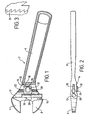
- an adjustable spanner 2 having a first jaw 4, integral with the handle 6 and second jaw 8 slidable with respect to the first jaw 4.
- the second jaw 8 has a spigot 10 which is slidably mounted within a bore 12 formed in the head 14 of the spanner 2.
- the slidable jaw 8 is prevented from falling out by a stop screw 15.
- a generally rectangular locking member 16 is moveable in a direction perpendicular to the direction of movement of the second jaw 8 from a locking position in which it engages the second jaw 8 to lock the second jaw 8 in a position relative to the first jaw 4 and a release position in which it releases the second jaw 8.
- the locking member 16 is mounted within a slot 18 extending through the head of the spanner in a direction parallel to the direction of movement of the second jaw 8.
- the locking member 16 is positioned in a desired position along the slot by virtue of two set screws 20, 22 which are received in a threaded bore 24 extending along the length of the slot 18.
- the opposed faces of the locking member 16 and the sliding jaw 8 are provided with sets of interlocking ratchet-like teeth 26, as illustrated in Figure 3 which engage at the interface 28.
- the pitch of the teeth 26 may be set at metric, imperial or any other measuring system. By setting the teeth pitch to match a predetermined measuring system, a correct fit will be ensured with a nut sized in the same system. It can be seen from Figure 3 that the teeth 26 have a slight backward slope generally which tends to force the locking member 16 further into engagement with the second jaw 8 when a force tending to separate the jaws 4, 8 is applied at the work face, leading to improved grip and preventing slippage of the spanner in use.
- a bow spring 30 is arranged in the slot 18 behind the locking member 16 so as to bias the sliding jaw 8 into its locking position with the teeth 26 of the jaw 8 and locking member 16 engaged.
- the spring 30 also acts to maintain the teeth 26 interengaged while the spanner is in use, preventing loosening of the spanner.
- a release button 32 is provided which permits the locking member 16 to be released against the biasing force of the spring 30.
- the release button 32 is fastened e.g screwed to the locking member 16 and protrudes through a slot 34 in a face of the spanner head 14 as shown in Figure 2.
- the release button 32 is pulled back in a direction away from the sliding jaw 8 so as to disengage the teeth 26 along the interface 28.
- the jaw 8 can slide freely within the bore 12 and if held in the correctly orientation will fall back against the stop screw 15.
- the spanner can then be placed over a nut and closed onto the nut by finger pressure.
- 8 it may not be necessary to pull back the release button 32 as the teeth may move over each other when pushed in this direction.
- the button 32 is released and the teeth 26 move into engagement under the force of the spring 30 and/or by the button 32 being pushed back in that direction.
- FIG. 4 A second embodiment of the invention is shown in Figure 4. This is generally similar to the embodiment of Figure 1, so only the differences will be described here.
- the locking member 38 has a notch 40 formed in its rear surface for receiving a complementary projection 42 formed in a generally V-shaped spring 44. This notch 40 locates the spring in the slot 46 preventing it falling out.
- the spanner described solves the problems found in the conventional adjustable spanner by locking the jaws precisely to the nut size through the action of the teeth gripping at the interface.
- the spanner can also very easily be set to another nut size.
Landscapes
- Engineering & Computer Science (AREA)
- Mechanical Engineering (AREA)
- Details Of Spanners, Wrenches, And Screw Drivers And Accessories (AREA)
- Valve Device For Special Equipments (AREA)
- Paper (AREA)
- Devices For Conveying Motion By Means Of Endless Flexible Members (AREA)
Claims (17)
- Clé à molette (2) comprenant ;
une première mâchoire (4) ;
une seconde mâchoire (8) montée coulissante par rapport à ladite première mâchoire (4) ;
un élément de blocage (16) mobile entre une position de blocage dans laquelle il vient en prise avec ladite seconde mâchoire (8) afin de bloquer la seconde mâchoire (8) en position par rapport à la première mâchoire (4), et une position de libération dans laquelle il libère ladite seconde mâchoire (8) ;
des moyens de rappel (30) pour rappeler l'élément de blocage (16) vers sa position de blocage, et
des moyens de libération (32) pour déplacer ledit élément de blocage (16) hors de ladite position de blocage vers sa position de libération contre la force exercée par lesdits moyens de rappel (30) ;
ledit élément de blocage (16) et ladite seconde mâchoire (8) ayant en surface des dents (26) d'enclenchement réciproque ;
lesdites dents s'étendant le long de surfaces opposées de la seconde mâchoire (8) et de l'élément de blocage (16) ;
dans laquelle lesdites surfaces opposées sont parallèles à la direction du déplacement de la seconde mâchoire (8) ;
caractérisée en ce que
lesdites dents sont en forme de dents de scie ; et en ce que
lesdites dents de scie sont inclinées vers l'arrière par rapport aux surfaces opposées, de telle sorte qu'au cas où une force est appliquée à la seconde mâchoire (8) dans une direction qui tend à accroítre la distance entre les mâchoires (4, 8) les dents agissent pour mettre l'élément de blocage et la seconde mâchoire (8) davantage en prise dans ladite position de blocage. - Clé à molette (2) selon la revendication 1, dans laquelle ledit élément de blocage (16) est agencé pour se déplacer dans une direction globalement perpendiculaire à la direction du déplacement de la seconde mâchoire (8).
- Clé à molette (2) selon la revendication 2, dans laquelle ledit élément de blocage (16) est agencé dans une fente (18) qui s'étend à travers la tête de la clé (2).
- Clé à molette (2) selon la revendication 3, dans laquelle ladite fente (18) s'étend dans l'ensemble parallèlement à la direction du déplacement de la seconde mâchoire (8).
- Clé à molette (2) selon la revendication 4, comprenant des moyens (20, 22) pour positionner de manière réglable ledit élément de blocage (16) à l'intérieur de la fente (18).
- Clé à molette (2) selon la revendication 5, dans laquelle lesdits moyens de positionnement comprennent des vis de réglage (20, 22).
- Clé à molette (2) selon la revendication 6, dans laquelle lesdites vis de réglage (20, 22) sont reçues dans un alésage fileté (24) s'étendant le long de ladite fente (18).
- Clé à molette (2) selon l'une quelconque des revendications précédentes, dans laquelle les moyens de rappel (30) comprennent un ressort.
- Clé à molette (2) selon la revendication 8, dans laquelle ledit ressort est un ressort à boudin.
- Clé à molette (2) selon la revendication 8, dans laquelle ledit ressort est un ressort à lames (30, 44).
- Clé à molette (2) selon la revendication 10, dans laquelle ledit ressort à lames (30) présente une forme arquée.
- Clé à molette (2) selon la revendication 10, dans laquelle ledit ressort à lames (44) présente globalement une forme en V.
- Clé à molette (2) selon l'une quelconque des revendications précédentes, dans laquelle ledit élément de blocage (16) comprend des moyens de positionnement desdits moyens de rappel.
- Clé à molette (2) selon la revendication 13, dans laquelle lesdits moyens de positionnement comprennent une encoche (40) pour recevoir une saillie formée sur les moyens de rappel (30).
- Clé à molette (2) selon l'une quelconque des revendications précédentes, dans laquelle lesdits moyens de libération (32) comprennent un élément de libération couplé à l'élément de blocage (16) et qui s'étend à partir de la clé (2) à l'usage d'un utilisateur.
- Clé à molette (2) selon la revendication 15, dans laquelle l'élément de libération (32) comprend un bouton qui s'étend à travers une fente (34) dans une face de la tête de la clé et qui est mobile dans la direction s'éloignant de la seconde mâchoire (8) pour libérer les moyens de blocage (16).
- Clé à molette (2) selon la revendication 16, dans laquelle ledit bouton est ajusté par vis sur ledit élément de blocage (16) à travers ladite fente (34).
Applications Claiming Priority (3)
| Application Number | Priority Date | Filing Date | Title |
|---|---|---|---|
| GB0120603 | 2001-08-24 | ||
| GBGB0120603.6A GB0120603D0 (en) | 2001-08-24 | 2001-08-24 | Adjustable spanner |
| PCT/GB2002/003878 WO2003018262A1 (fr) | 2001-08-24 | 2002-08-22 | Cle a molette |
Publications (2)
| Publication Number | Publication Date |
|---|---|
| EP1419035A1 EP1419035A1 (fr) | 2004-05-19 |
| EP1419035B1 true EP1419035B1 (fr) | 2005-11-02 |
Family
ID=9920922
Family Applications (1)
| Application Number | Title | Priority Date | Filing Date |
|---|---|---|---|
| EP02751449A Expired - Lifetime EP1419035B1 (fr) | 2001-08-24 | 2002-08-22 | Cle a molette |
Country Status (12)
| Country | Link |
|---|---|
| US (1) | US7077034B2 (fr) |
| EP (1) | EP1419035B1 (fr) |
| JP (1) | JP2005512822A (fr) |
| CN (1) | CN1545442A (fr) |
| AT (1) | ATE308406T1 (fr) |
| AU (1) | AU2002356110B2 (fr) |
| CA (1) | CA2458480C (fr) |
| DE (1) | DE60207088T2 (fr) |
| ES (1) | ES2248585T3 (fr) |
| GB (1) | GB0120603D0 (fr) |
| MX (1) | MXPA04001565A (fr) |
| WO (1) | WO2003018262A1 (fr) |
Cited By (1)
| Publication number | Priority date | Publication date | Assignee | Title |
|---|---|---|---|---|
| TWI794020B (zh) * | 2021-12-24 | 2023-02-21 | 鴻安國際興業有限公司 | 快速活動扳手 |
Families Citing this family (6)
| Publication number | Priority date | Publication date | Assignee | Title |
|---|---|---|---|---|
| GB2388806B (en) * | 2002-05-21 | 2006-01-25 | Victor Martin Goddard | Tool |
| US7275464B2 (en) * | 2005-08-02 | 2007-10-02 | Irwin Industrial Tool Company | Ratcheting adjustable wrench |
| US20070175300A1 (en) * | 2005-08-02 | 2007-08-02 | Burry James M | Adjustable wrench |
| US20070125205A1 (en) * | 2005-12-05 | 2007-06-07 | Beckwith Jonathan S | Robust slide adjustable wrench |
| CN100560299C (zh) * | 2007-11-12 | 2009-11-18 | 伯鑫工具股份有限公司 | 活动扳手 |
| TWI767517B (zh) * | 2021-01-14 | 2022-06-11 | 亨龍工業有限公司 | 可調整扳手 |
Family Cites Families (9)
| Publication number | Priority date | Publication date | Assignee | Title |
|---|---|---|---|---|
| US1368580A (en) * | 1920-08-12 | 1921-02-15 | Ernest E Sievert | Wrench |
| US1440381A (en) * | 1920-12-27 | 1923-01-02 | Otto E Edstrom | Adjustable wrench |
| FR539780A (fr) * | 1921-02-16 | 1922-06-30 | Perfectionnements aux clefs à écrous à ouverture variable | |
| US1397214A (en) * | 1921-04-16 | 1921-11-15 | Titus S Hose | Wrench |
| US2582591A (en) * | 1950-06-26 | 1952-01-15 | Maxwell K Hicks | Latch for slidable side jaw wrenches |
| US2850932A (en) * | 1956-12-19 | 1958-09-09 | Teofil L Bonkowski | Spring-biased latch means for a sliding jaw wrench |
| US3817128A (en) * | 1972-08-14 | 1974-06-18 | J Evans | Rapidly adjustable wrench |
| CN2070226U (zh) | 1990-02-15 | 1991-01-30 | 周山 | 高效活扳手 |
| CN2063855U (zh) | 1990-02-26 | 1990-10-17 | 周维捷 | 快速活扳手 |
-
2001
- 2001-08-24 GB GBGB0120603.6A patent/GB0120603D0/en not_active Ceased
-
2002
- 2002-08-22 US US10/487,799 patent/US7077034B2/en not_active Expired - Fee Related
- 2002-08-22 AT AT02751449T patent/ATE308406T1/de not_active IP Right Cessation
- 2002-08-22 MX MXPA04001565A patent/MXPA04001565A/es active IP Right Grant
- 2002-08-22 ES ES02751449T patent/ES2248585T3/es not_active Expired - Lifetime
- 2002-08-22 EP EP02751449A patent/EP1419035B1/fr not_active Expired - Lifetime
- 2002-08-22 CA CA2458480A patent/CA2458480C/fr not_active Expired - Fee Related
- 2002-08-22 JP JP2003522762A patent/JP2005512822A/ja active Pending
- 2002-08-22 CN CNA028164180A patent/CN1545442A/zh active Pending
- 2002-08-22 DE DE60207088T patent/DE60207088T2/de not_active Expired - Lifetime
- 2002-08-22 WO PCT/GB2002/003878 patent/WO2003018262A1/fr not_active Ceased
- 2002-08-22 AU AU2002356110A patent/AU2002356110B2/en not_active Ceased
Cited By (1)
| Publication number | Priority date | Publication date | Assignee | Title |
|---|---|---|---|---|
| TWI794020B (zh) * | 2021-12-24 | 2023-02-21 | 鴻安國際興業有限公司 | 快速活動扳手 |
Also Published As
| Publication number | Publication date |
|---|---|
| HK1066187A1 (en) | 2005-03-18 |
| CA2458480C (fr) | 2011-04-26 |
| US7077034B2 (en) | 2006-07-18 |
| CN1545442A (zh) | 2004-11-10 |
| US20050016329A1 (en) | 2005-01-27 |
| CA2458480A1 (fr) | 2003-03-06 |
| GB0120603D0 (en) | 2001-10-17 |
| ATE308406T1 (de) | 2005-11-15 |
| EP1419035A1 (fr) | 2004-05-19 |
| JP2005512822A (ja) | 2005-05-12 |
| WO2003018262A1 (fr) | 2003-03-06 |
| MXPA04001565A (es) | 2004-11-22 |
| AU2002356110B2 (en) | 2008-03-06 |
| ES2248585T3 (es) | 2006-03-16 |
| DE60207088T2 (de) | 2006-07-13 |
| DE60207088D1 (de) | 2005-12-08 |
Similar Documents
| Publication | Publication Date | Title |
|---|---|---|
| US8056451B2 (en) | Locking pliers | |
| US6568300B1 (en) | Ratcheting open-end wrenches | |
| US4437364A (en) | Nut wrench | |
| US11850711B2 (en) | Torque wrench | |
| US20190009393A1 (en) | Span-adjustable wrench | |
| US2562060A (en) | Slidable side jaw socket wrench | |
| WO1999029471A1 (fr) | Cle a cliquet muni d'un mors reglable | |
| US20110239832A1 (en) | Adjustable wrenches | |
| EP1419035B1 (fr) | Cle a molette | |
| US7117768B1 (en) | Adjustable wrench | |
| WO2017153742A2 (fr) | Outils de préhension manuels | |
| CN2181371Y (zh) | 可调整扳手 | |
| US10328553B1 (en) | Adjustable open ended wrench with bidirectional release action | |
| AU2002356110A1 (en) | Adjustable spanner | |
| US4028969A (en) | Adjustable wrench | |
| US6145415A (en) | Adjustable pliers | |
| US20190084130A1 (en) | Hand Operated Gripping Tool | |
| HK1066187B (en) | Adjustable spanner | |
| EP4393647A1 (fr) | Clé à écrous | |
| US3956949A (en) | Wrench with quick adjusting sliding jaw and self tightening anvil jaw | |
| GB2113132A (en) | Adjustable wrench | |
| US5746098A (en) | Adjustable spanners | |
| US3093019A (en) | Adjustable jaw wrench | |
| CN1034000C (zh) | 活动扳手 | |
| KR102038018B1 (ko) | 다기능 체결 공구 |
Legal Events
| Date | Code | Title | Description |
|---|---|---|---|
| PUAI | Public reference made under article 153(3) epc to a published international application that has entered the european phase |
Free format text: ORIGINAL CODE: 0009012 |
|
| 17P | Request for examination filed |
Effective date: 20040223 |
|
| AK | Designated contracting states |
Kind code of ref document: A1 Designated state(s): AT BE BG CH CY CZ DE DK EE ES FI FR GB GR IE IT LI LU MC NL PT SE SK TR |
|
| AX | Request for extension of the european patent |
Extension state: AL LT LV MK RO SI |
|
| REG | Reference to a national code |
Ref country code: HK Ref legal event code: DE Ref document number: 1066187 Country of ref document: HK |
|
| GRAP | Despatch of communication of intention to grant a patent |
Free format text: ORIGINAL CODE: EPIDOSNIGR1 |
|
| GRAS | Grant fee paid |
Free format text: ORIGINAL CODE: EPIDOSNIGR3 |
|
| RAP1 | Party data changed (applicant data changed or rights of an application transferred) |
Owner name: HTM PRODUCTS LTD. |
|
| GRAA | (expected) grant |
Free format text: ORIGINAL CODE: 0009210 |
|
| AK | Designated contracting states |
Kind code of ref document: B1 Designated state(s): AT BE BG CH CY CZ DE DK EE ES FI FR GB GR IE IT LI LU MC NL PT SE SK TR |
|
| AX | Request for extension of the european patent |
Extension state: AL LT LV MK RO SI |
|
| PG25 | Lapsed in a contracting state [announced via postgrant information from national office to epo] |
Ref country code: AT Free format text: LAPSE BECAUSE OF FAILURE TO SUBMIT A TRANSLATION OF THE DESCRIPTION OR TO PAY THE FEE WITHIN THE PRESCRIBED TIME-LIMIT Effective date: 20051102 Ref country code: BE Free format text: LAPSE BECAUSE OF FAILURE TO SUBMIT A TRANSLATION OF THE DESCRIPTION OR TO PAY THE FEE WITHIN THE PRESCRIBED TIME-LIMIT Effective date: 20051102 Ref country code: LI Free format text: LAPSE BECAUSE OF FAILURE TO SUBMIT A TRANSLATION OF THE DESCRIPTION OR TO PAY THE FEE WITHIN THE PRESCRIBED TIME-LIMIT Effective date: 20051102 Ref country code: FI Free format text: LAPSE BECAUSE OF FAILURE TO SUBMIT A TRANSLATION OF THE DESCRIPTION OR TO PAY THE FEE WITHIN THE PRESCRIBED TIME-LIMIT Effective date: 20051102 Ref country code: SK Free format text: LAPSE BECAUSE OF FAILURE TO SUBMIT A TRANSLATION OF THE DESCRIPTION OR TO PAY THE FEE WITHIN THE PRESCRIBED TIME-LIMIT Effective date: 20051102 Ref country code: NL Free format text: LAPSE BECAUSE OF FAILURE TO SUBMIT A TRANSLATION OF THE DESCRIPTION OR TO PAY THE FEE WITHIN THE PRESCRIBED TIME-LIMIT Effective date: 20051102 Ref country code: CH Free format text: LAPSE BECAUSE OF FAILURE TO SUBMIT A TRANSLATION OF THE DESCRIPTION OR TO PAY THE FEE WITHIN THE PRESCRIBED TIME-LIMIT Effective date: 20051102 Ref country code: CZ Free format text: LAPSE BECAUSE OF FAILURE TO SUBMIT A TRANSLATION OF THE DESCRIPTION OR TO PAY THE FEE WITHIN THE PRESCRIBED TIME-LIMIT Effective date: 20051102 |
|
| REG | Reference to a national code |
Ref country code: GB Ref legal event code: FG4D |
|
| REG | Reference to a national code |
Ref country code: CH Ref legal event code: EP |
|
| REG | Reference to a national code |
Ref country code: SE Ref legal event code: TRGR |
|
| REF | Corresponds to: |
Ref document number: 60207088 Country of ref document: DE Date of ref document: 20051208 Kind code of ref document: P |
|
| PG25 | Lapsed in a contracting state [announced via postgrant information from national office to epo] |
Ref country code: GR Free format text: LAPSE BECAUSE OF FAILURE TO SUBMIT A TRANSLATION OF THE DESCRIPTION OR TO PAY THE FEE WITHIN THE PRESCRIBED TIME-LIMIT Effective date: 20060202 Ref country code: DK Free format text: LAPSE BECAUSE OF FAILURE TO SUBMIT A TRANSLATION OF THE DESCRIPTION OR TO PAY THE FEE WITHIN THE PRESCRIBED TIME-LIMIT Effective date: 20060202 Ref country code: BG Free format text: LAPSE BECAUSE OF FAILURE TO SUBMIT A TRANSLATION OF THE DESCRIPTION OR TO PAY THE FEE WITHIN THE PRESCRIBED TIME-LIMIT Effective date: 20060202 |
|
| REG | Reference to a national code |
Ref country code: ES Ref legal event code: FG2A Ref document number: 2248585 Country of ref document: ES Kind code of ref document: T3 |
|
| PG25 | Lapsed in a contracting state [announced via postgrant information from national office to epo] |
Ref country code: PT Free format text: LAPSE BECAUSE OF FAILURE TO SUBMIT A TRANSLATION OF THE DESCRIPTION OR TO PAY THE FEE WITHIN THE PRESCRIBED TIME-LIMIT Effective date: 20060403 |
|
| LTIE | Lt: invalidation of european patent or patent extension |
Effective date: 20051102 |
|
| NLV1 | Nl: lapsed or annulled due to failure to fulfill the requirements of art. 29p and 29m of the patents act | ||
| REG | Reference to a national code |
Ref country code: HK Ref legal event code: GR Ref document number: 1066187 Country of ref document: HK |
|
| REG | Reference to a national code |
Ref country code: CH Ref legal event code: PL |
|
| ET | Fr: translation filed | ||
| PG25 | Lapsed in a contracting state [announced via postgrant information from national office to epo] |
Ref country code: MC Free format text: LAPSE BECAUSE OF NON-PAYMENT OF DUE FEES Effective date: 20060831 |
|
| PLBE | No opposition filed within time limit |
Free format text: ORIGINAL CODE: 0009261 |
|
| STAA | Information on the status of an ep patent application or granted ep patent |
Free format text: STATUS: NO OPPOSITION FILED WITHIN TIME LIMIT |
|
| 26N | No opposition filed |
Effective date: 20060803 |
|
| PG25 | Lapsed in a contracting state [announced via postgrant information from national office to epo] |
Ref country code: EE Free format text: LAPSE BECAUSE OF FAILURE TO SUBMIT A TRANSLATION OF THE DESCRIPTION OR TO PAY THE FEE WITHIN THE PRESCRIBED TIME-LIMIT Effective date: 20051102 |
|
| PG25 | Lapsed in a contracting state [announced via postgrant information from national office to epo] |
Ref country code: TR Free format text: LAPSE BECAUSE OF FAILURE TO SUBMIT A TRANSLATION OF THE DESCRIPTION OR TO PAY THE FEE WITHIN THE PRESCRIBED TIME-LIMIT Effective date: 20051102 Ref country code: LU Free format text: LAPSE BECAUSE OF NON-PAYMENT OF DUE FEES Effective date: 20060822 |
|
| PG25 | Lapsed in a contracting state [announced via postgrant information from national office to epo] |
Ref country code: CY Free format text: LAPSE BECAUSE OF FAILURE TO SUBMIT A TRANSLATION OF THE DESCRIPTION OR TO PAY THE FEE WITHIN THE PRESCRIBED TIME-LIMIT Effective date: 20051102 |
|
| REG | Reference to a national code |
Ref country code: IE Ref legal event code: MM4A |
|
| PG25 | Lapsed in a contracting state [announced via postgrant information from national office to epo] |
Ref country code: IE Free format text: LAPSE BECAUSE OF NON-PAYMENT OF DUE FEES Effective date: 20080822 |
|
| PGFP | Annual fee paid to national office [announced via postgrant information from national office to epo] |
Ref country code: IE Payment date: 20071025 Year of fee payment: 6 |
|
| PGFP | Annual fee paid to national office [announced via postgrant information from national office to epo] |
Ref country code: SE Payment date: 20130812 Year of fee payment: 12 |
|
| PGFP | Annual fee paid to national office [announced via postgrant information from national office to epo] |
Ref country code: DE Payment date: 20140813 Year of fee payment: 13 |
|
| PGFP | Annual fee paid to national office [announced via postgrant information from national office to epo] |
Ref country code: ES Payment date: 20140814 Year of fee payment: 13 Ref country code: FR Payment date: 20140812 Year of fee payment: 13 |
|
| PGFP | Annual fee paid to national office [announced via postgrant information from national office to epo] |
Ref country code: IT Payment date: 20140818 Year of fee payment: 13 |
|
| REG | Reference to a national code |
Ref country code: SE Ref legal event code: EUG |
|
| PG25 | Lapsed in a contracting state [announced via postgrant information from national office to epo] |
Ref country code: SE Free format text: LAPSE BECAUSE OF NON-PAYMENT OF DUE FEES Effective date: 20140823 |
|
| REG | Reference to a national code |
Ref country code: DE Ref legal event code: R119 Ref document number: 60207088 Country of ref document: DE |
|
| PG25 | Lapsed in a contracting state [announced via postgrant information from national office to epo] |
Ref country code: IT Free format text: LAPSE BECAUSE OF NON-PAYMENT OF DUE FEES Effective date: 20150822 |
|
| REG | Reference to a national code |
Ref country code: FR Ref legal event code: ST Effective date: 20160429 |
|
| PG25 | Lapsed in a contracting state [announced via postgrant information from national office to epo] |
Ref country code: DE Free format text: LAPSE BECAUSE OF NON-PAYMENT OF DUE FEES Effective date: 20160301 |
|
| PG25 | Lapsed in a contracting state [announced via postgrant information from national office to epo] |
Ref country code: FR Free format text: LAPSE BECAUSE OF NON-PAYMENT OF DUE FEES Effective date: 20150831 |
|
| REG | Reference to a national code |
Ref country code: ES Ref legal event code: FD2A Effective date: 20170202 |
|
| PG25 | Lapsed in a contracting state [announced via postgrant information from national office to epo] |
Ref country code: ES Free format text: LAPSE BECAUSE OF NON-PAYMENT OF DUE FEES Effective date: 20150823 |
|
| PGFP | Annual fee paid to national office [announced via postgrant information from national office to epo] |
Ref country code: GB Payment date: 20170819 Year of fee payment: 16 |
|
| GBPC | Gb: european patent ceased through non-payment of renewal fee |
Effective date: 20180822 |
|
| PG25 | Lapsed in a contracting state [announced via postgrant information from national office to epo] |
Ref country code: GB Free format text: LAPSE BECAUSE OF NON-PAYMENT OF DUE FEES Effective date: 20180822 |