EP1419344B1 - Taschenlampe mit ersatzglühbirne - Google Patents
Taschenlampe mit ersatzglühbirne Download PDFInfo
- Publication number
- EP1419344B1 EP1419344B1 EP02794824A EP02794824A EP1419344B1 EP 1419344 B1 EP1419344 B1 EP 1419344B1 EP 02794824 A EP02794824 A EP 02794824A EP 02794824 A EP02794824 A EP 02794824A EP 1419344 B1 EP1419344 B1 EP 1419344B1
- Authority
- EP
- European Patent Office
- Prior art keywords
- cap
- opening
- diameter
- closest
- replacement lamp
- Prior art date
- Legal status (The legal status is an assumption and is not a legal conclusion. Google has not performed a legal analysis and makes no representation as to the accuracy of the status listed.)
- Expired - Lifetime
Links
- 230000001681 protective effect Effects 0.000 claims abstract description 9
- 230000007704 transition Effects 0.000 claims description 3
- 230000004308 accommodation Effects 0.000 abstract 1
- 230000006835 compression Effects 0.000 abstract 1
- 238000007906 compression Methods 0.000 abstract 1
- 230000014759 maintenance of location Effects 0.000 abstract 1
- 230000035939 shock Effects 0.000 description 4
- 239000004020 conductor Substances 0.000 description 3
- 239000011521 glass Substances 0.000 description 2
- 238000004519 manufacturing process Methods 0.000 description 2
- 238000003825 pressing Methods 0.000 description 2
- 239000007787 solid Substances 0.000 description 2
- 240000000731 Fagus sylvatica Species 0.000 description 1
- 235000010099 Fagus sylvatica Nutrition 0.000 description 1
- 230000005489 elastic deformation Effects 0.000 description 1
- 230000002349 favourable effect Effects 0.000 description 1
- 239000006261 foam material Substances 0.000 description 1
- 238000000034 method Methods 0.000 description 1
- 238000003801 milling Methods 0.000 description 1
Images
Classifications
-
- F—MECHANICAL ENGINEERING; LIGHTING; HEATING; WEAPONS; BLASTING
- F21—LIGHTING
- F21V—FUNCTIONAL FEATURES OR DETAILS OF LIGHTING DEVICES OR SYSTEMS THEREOF; STRUCTURAL COMBINATIONS OF LIGHTING DEVICES WITH OTHER ARTICLES, NOT OTHERWISE PROVIDED FOR
- F21V19/00—Fastening of light sources or lamp holders
- F21V19/04—Fastening of light sources or lamp holders with provision for changing light source, e.g. turret
- F21V19/047—Fastening of light sources or lamp holders with provision for changing light source, e.g. turret by using spare light sources comprised in or attached to the lighting device and being intended to replace a defect light source by manual mounting
-
- F—MECHANICAL ENGINEERING; LIGHTING; HEATING; WEAPONS; BLASTING
- F21—LIGHTING
- F21L—LIGHTING DEVICES OR SYSTEMS THEREOF, BEING PORTABLE OR SPECIALLY ADAPTED FOR TRANSPORTATION
- F21L4/00—Electric lighting devices with self-contained electric batteries or cells
- F21L4/005—Electric lighting devices with self-contained electric batteries or cells the device being a pocket lamp
-
- F—MECHANICAL ENGINEERING; LIGHTING; HEATING; WEAPONS; BLASTING
- F21—LIGHTING
- F21V—FUNCTIONAL FEATURES OR DETAILS OF LIGHTING DEVICES OR SYSTEMS THEREOF; STRUCTURAL COMBINATIONS OF LIGHTING DEVICES WITH OTHER ARTICLES, NOT OTHERWISE PROVIDED FOR
- F21V15/00—Protecting lighting devices from damage
- F21V15/04—Resilient mountings, e.g. shock absorbers
Definitions
- the invention relates to a torch with flashlight with a battery housing (2), with a housing opening (6) for receiving flashlight batteries (3), a closure cap (7) for the housing opening (6), with an opening side (9) and an opposite side cap (10), a replacement lamp (13) having between a first (13a) and a second end (13b) a socket having an at least partially circumferential collar (14), in the closure cap (7) arranged holding means (12a, 12b) for the replacement lamp (13), which are formed such that the first end (13a) of the replacement lamp (13) of the holding means (12a, 12b) projecting opening side, at least one opening side of the holding means (12a, 12b) projecting contact spring (5), which is elastically deformable in the direction of the cap side (10) for pressure bearing of the flashlight batteries (3), a fixed protective element (15) arranged at the first end (13a) of the replacement light (13), which open a support (11) on a Kappeninnenwandung (8a, 8b) of the closure cap (7), and a first
- Flashlights with replacement lights are basically known.
- the flashlights have a battery housing with a housing opening.
- the housing opening can be closed with a closure cap.
- a replacement bulb is added.
- the replacement bulb is usually recorded so that the actual glass bulb is directed away with the filament of the flashlight battery.
- the bulb pole points to the flashlight battery.
- the bulb pole is surrounded by a spiral spring, which is elastically deformable in the direction of the closure cap.
- a disadvantage of such Flashlights is that the pole of the replacement bulb is exposed to shocks of the flashlight battery and can be damaged.
- US-A-3,829,676 discloses a flashlight with a spare lamp arranged in a cap.
- the replacement lamp is provided with a collar arranged on the socket, between the cap and the bottom of the collar is arranged a cylindrical coil spring.
- a holding element in the form of a perforated plate is provided on the top of the cap.
- a conical coil spring is provided on the side facing away from the cap side of the perforated plate.
- Within the cap an externally disposed sleeve is provided, which is provided with a shoulder. Due to the conical spiral spring, the perforated plate can be pressed down to the heel. Then facing away from the socket lighting part of the replacement light is completely within the sleeve.
- the pressing down of the perforated plate and thus the replacement lamp takes place against the cylindrical coil spring which acts between the outer closure lid and the underside of the collar of the replacement lamp socket.
- the disadvantage here is that the luminous part of the bulbs can protrude beyond the sleeve. This is the case when the force of the cylindrical coil spring pushes outwards more than the conical spiral spring counteracts. There is thus a risk that the replacement lamp may be damaged when the conical coil spring is pressed together, for example, by batteries inserted, but the force developed during assembly force on the perforated disc is not greater than the counteracting force of the cylindrical coil spring.
- US-A-6 135 616 discloses a mini flashlight, in which also a closure cap side, a replacement light is provided. Also at This flashlight is a danger that the replacement bulb can be damaged by the batteries.
- US-A-1 661 784 discloses a flashlight in which the replacement bulb is placed in a separate compartment and held by webs. There is a risk that the replacement bulb will break away from the bars and get in motion within the compartment and may be damaged.
- U.S.-A-4,951,183 discloses a flashlight in which a replacement bulb is disposed in a tubular member of foam material within a coil spring. Also with this flashlight there is a risk that the replacement bulb will be damaged if the spring, for example, when inserting the batteries is highly compressed, as the Optimizglühbime extends beyond the support point of the coil spring in the battery receiving space addition.
- Object of the present invention is to improve the known prior art flashlights so that the replacement bulb can not be damaged by the flashlight batteries used.
- the object is achieved according to the invention in that as a further holding means (12a, 12b) a second perforated disc (12b) for pushing the second end (13b) of the replacement lamp is provided, the diameter of the second perforated disc (12b) for interacting with the support (12b). 11), and that the diameters of the holes of the first (12a) and second perforated disks (12b) are smaller than the diameter of the collar (14) of the replacement lamp (13).
- the flashlight according to the invention has a replacement light. It can be a light bulb with filament.
- the replacement light is held by retaining means in the cap.
- the first end of the replacement light can protrude beyond the opening side of the cap out into the battery housing of the flashlight when the cap closes the housing opening.
- It can be provided but also a plurality of opening side protruding from the holding means contact springs, the contact spring is stretched when inserted into the battery case flashlight battery and cap applied elastic in the direction of the cap side of the cap.
- the pocket lamp battery is prevented by the contact spring at the back and Herrisonen by slight vibrations of the flashlight.
- the contact spring may be elastically deformable in the direction of the cap side beyond the first end of the luminaire.
- a solid protective element is arranged at the first end of the replacement lamp.
- the protective element is formed such that the shocks of the Taschenlampenbuciterien be intercepted by the protective element and prevent direct contact between the flashlight battery and the first end of the replacement lamp.
- the closure cap has a support on a cap inner wall.
- the support can interact with the holding means.
- the cap inner wall is formed substantially cylindrical.
- the battery case is cylindrically shaped to receive a cylindrically shaped flashlight battery.
- the cap inner wall of the invention continues the battery housing interior cylindrical.
- the cap outer wall can also be cylindrical.
- the cap inner wall has a first and a second diameter, which is larger than the first diameter and the support is formed by the transition from the cap inner wall with the first diameter to the cap inner wall with the second diameter.
- the cap of this embodiment is easy to make by milling the inside of the cap.
- the opening-side end of the closure cap is flared on the opening side.
- the holding means on a first perforated disc for pushing the first end of the replacement lamp on and a second perforated disc for pushing the second end of the replacement lamp on and the diameter of the second perforated disc is designed to cooperate with the support.
- the first and second perforated disc may be circular.
- the second perforated disc lies directly on the support.
- the first perforated disc is arranged next to the second perforated disc.
- the diameter of the preferably circular perforated discs is at best equal and slightly smaller than the second diameter of the cap inner wall and larger than the first diameter of the cap inner wall.
- the replacement lamp between the first and second end of a socket, which has at least partially the spare light circumferential collar.
- the holding means described above are particularly useful in connection with such a replacement lamp.
- the outer diameter of the collar is larger than the diameter of the preferably circular holes of the perforated discs.
- the first perforated disk can be guided over the first end of the replacement lamp and the second perforated disk can be guided over the second end of the replacement lamp.
- the collar can be fixed between the two perforated disks by pressing the two perforated disks against each other.
- the at least one contact spring on an opening side tapered coil spring with a cap-side end, wherein the relaxed cap-side end has a slightly larger diameter than the first diameter of the cap inner wall.
- the spiral spring is fundamentally not only elastically deformable in the direction of its spiral course, but also transversely thereto.
- the cap-side end of the coil spring is compressible and clamped under tension in the Kappeninnenwandung with the first diameter.
- the process of clamping is preferably carried out via the opening side conically widening opening-side end of the closure cap.
- the protective element as a socket with a cap-side end and a formed opening side end and the socket is feasible on the first end of the replacement lamp and its cap-side end is intended for opening-side stop on the first perforated disc and its opening side end is beyond the first end of the spare light out the opening side.
- the socket has on the inside wall at the cap-side end molded projections.
- the projections press the socket to the first end of the replacement lamp.
- the socket can not slip off automatically from the first end of the replacement lamp.
- the book is preferably dimensioned in length so that its cap-side end abuts the first perforated disc and its opening-side end projects beyond the first end of the replacement lamp in the direction of the battery when the cap is applied. The first end of the replacement light is thus completely absorbed lengthwise inside the socket.
- the flashlight 1 has a battery housing 2, in which a three-cell rechargeable flashlight battery 3 is inserted.
- the positive pole of the flashlight battery 3 is in electrical contact with a positive conductor means 4.
- the negative pole of the flashlight battery 3 is in electrical contact with a contact spring 5.
- the battery case 2 has a housing opening 6, through which the flashlight battery 3 can be inserted and removed.
- the battery housing 2 has an internal thread in the region of the housing opening 6.
- the internal thread cooperates with an external thread of a closure cap 7.
- the screwed cap 7 is formed in the longitudinal direction of the battery case 2 is substantially cylindrical and has a cylindrical Kappeninnenwandung 8a, 8b.
- the closure cap 7 has an opening side 9 and a parallel opposite cap side 10.
- the cap side 10 is completely closed.
- the external thread is arranged in the region of the opening side 9 of the closure cap 7.
- the cylindrical cap inner wall 8a, 8b has a first diameter 8a on the cap side, and adjoins it on the opening side a cap inner wall with a second, somewhat larger diameter 8b.
- the transition from the cap inner wall with the first diameter 8a to the cap inner wall with the second diameter 8b forms a support 11.
- holding means 12a, 12b for a spare bulb 13 On the support 11 are holding means 12a, 12b for a spare bulb 13.
- the holding means consist of a first 12a and a second perforated disc 12b, which have a same diameter and a same hole diameter.
- the first perforated disk 12a is arranged on the opening side parallel to the second perforated disk 12b, which lies directly on the support 11.
- the replacement bulb 13 has a first end 13a having a lamp pole and a second end 13b having an incandescent filament surrounding a glass bulb. Between the first end 13a and the second end 13b of the spare bulb, a circumferential collar 14 is formed. The outer diameter of the collar 14 is greater than the hole diameter of the perforated discs 12a, 12b. The replacement bulb 13 can thus be held on the collar 14 between the first 12a and the second perforated disc 12b. The distance between the second perforated disc 12b and the cap side 10 of the cap 7 is large enough to accommodate the second end 13b of the replacement bulb 13.
- the contact spring 5 is formed here as an opening side conically tapered coil spring.
- the coil spring 5 is at the same time negative conductor means of the flashlight 1. It has an opening-side end 5a and a cap-side end 5b.
- the opening-side end 5a has a smaller diameter than the cap-side end 5b.
- the cap-side end 5b of the coil spring can be clamped by slightly compressing the coil spring 5 into the closure cap 7 in the region of the cap inner wall with the second diameter 8b.
- the clamped in the cap 7 coil spring 5 holds the first 8a and second perforated disc 8b pressed firmly against the support 11.
- the replacement bulb 13 is thus fixed by its collar 14 in the cap 7.
- the coil spring 5 When screwed cap 7 and inserted flashlight battery 3, the coil spring 5 is compressed slightly towards the cap 7. The pressure bearing of the flashlight battery 3 prevents a back and forth of the Flashlight Battery 3.
- the opening-side end 9 of the cap 7 widens conically at an opening angle of about 45 ° to facilitate clamping of the cap-side end 5b of the coil spring.
- the cap 7 rotates cap side of the external thread an O-ring made of rubber.
- the first end 13a of the replacement bulb 13 is surrounded by a bush 15.
- the bush 15 is made of solid plastic.
- the bushing 15 has a cap-side end 15a which abuts against the first perforated disc 8b and an opening-side end 15b which terminates in the longitudinal direction at the level of the first end 13a of the replacement bulb 13.
- the inertia of the flashlight battery 3 could cause a deformation of the coil spring 5 in the direction of the closure cap 7 via the first end 13a of the replacement bulb 13 addition.
- the coil spring 5 is in principle compressible with a sufficiently high force almost in one plane.
- the bush 15 protects the first end 13a of the replacement bulb 13 in which it intercepts shocks of the flashlight battery 3 and passes over the first perforated disc 8b in the cap 7. The bushing 15 prevents a direct impact contact between Batterieminuspol and the first end 13 a of the replacement bulb 13th
- the flashlight 1 has at the opposite end of the cap 7 the flashlight head 16.
- the flashlight head 16 has an approximately centrally held bulb 17, which is surrounded by a parabolic reflector 18, which is completed by a lens 19 at the head end.
- the light bulb 17 is held by a socket on the flashlight head 16.
- the lens 19 and the reflector 18 are fixed to a unscrewable portion 20 of the Flashlight head connected.
- the collar of the bulb 17 forms a contact
- the battery housing facing pole of the bulb 17 forms another contact of the bulb 17 from.
- the other contact of the bulb 17 is electrically connected via a wire spring 21 to a switch 22.
- the switch 22 is in turn electrically connected to the positive conductor means 4.
Landscapes
- Engineering & Computer Science (AREA)
- General Engineering & Computer Science (AREA)
- Battery Mounting, Suspending (AREA)
- Arrangement Of Elements, Cooling, Sealing, Or The Like Of Lighting Devices (AREA)
- Semiconductor Lasers (AREA)
- Non-Portable Lighting Devices Or Systems Thereof (AREA)
- Investigating, Analyzing Materials By Fluorescence Or Luminescence (AREA)
Description
- Die Erfindung betrifft eine Taschenlampe mit Taschenlampe mit einem Batteriegehäuse (2), mit einer Gehäuseöffnung (6) zur Aufnahme von Taschenlampenbatterien (3), einer Verschlusskappe (7) für die Gehäuseöffnung (6), mit einer Öffnungsseite (9) und einer gegenüberliegenden Kappenseite (10), einer Ersatzleuchte (13), die zwischen einem ersten (13a) und einem zweiten Ende (13b) eine Fassung hat, die einen wenigstens teilweise umlaufenden Kragen (14) aufweist, in der Verschlußkappe (7) angeordneten Haltemitteln (12a, 12b) für die Ersatzleuchte (13), die derart ausgeformt sind, daß das erstes Ende (13a) der Ersatzleuchte (13) von den Haltemitteln (12a, 12b) öffnungsseitig absteht, wenigstens einer öffnungsseitig von den Haltemitteln (12a, 12b) abstehenden Kontaktfeder (5), die in Richtung Kappenseite (10) zur Drucklagerung der Taschenlampenbatterien (3) elastisch verformbar ist, einem am ersten Ende (13a) der Ersatzleuchte (13) angeordneten festen Schutzelement (15), das öffnungsseitig wenigstens bis zum ersten Ende (13a) der Ersatzleuchte (13) absteht, einer Auflage (11) an einer Kappeninnenwandung (8a, 8b) der Verschlusskappe (7), und einer ersten Lochscheibe (12a) zum Hindurchschieben des ersten Endes (13a) der Ersatzleuchte als ein Haltemittel.
- Taschenlampen mit Ersatzleuchten sind grundsätzlich bekannt. Die Taschenlampen weisen ein Batteriegehäuse mit einer Gehäuseöffnung auf. Die Gehäuseöffnung ist mit einer Verschlußkappe verschließbar. In dieser Verschlußkappe ist eine Ersatzglühbirne aufgenommen. Die Ersatzglühbirne ist dabei üblicherweise so aufgenommen, daß die eigentliche Glasbirne mit der Glühwendel von der Taschenlampenbatterie weggerichtet ist. Der Glühbirnenpol zeigt zur Taschenlampenbatterie. Der Glühbirnenpol ist dabei von einer Spiralfeder umgeben, die in Richtung der Verschlußkappe elastisch verformbar ist. Nachteilig an derartigen Taschenlampen ist, daß der Pol der Ersatzglühbirne Stößen der Taschenlampenbatterie ausgesetzt ist und beschädigt werden kann.
-
US-A-3 829 676 offenbart eine Taschenlampe mit einer in einer Verschlusskappe angeordneten Ersatzleuchte. Die Ersatzleuchte ist mit einem an der Fassung angeordnetem Kragen versehen, Zwischen Verschlusskappe und Unterseite des Kragens ist eine zylindrische Spiralfeder angeordnet. Auf der Oberseite der Kappe ist ein Halteelement in Form eines Lochblechs vorgesehen. Auf der von der Verschlusskappe abgewandten Seite des Lochblechs ist eine konische Spiralfeder vorgesehen. Innerhalb der Verschlusskappe ist eine außen angeordnete Hülse vorgesehen, die mit einem Absatz versehen ist. Durch die kegelförmige Spiralfeder kann das Lochblech bis zum Absatz heruntergedrückt werden. Dann befindet sich der von der Fassung abgewandte Leuchtteil der Ersatzleuchte vollständig innerhalb der Hülse. Das Herunterdrücken des Lochblechs und damit der Ersatzleuchte erfolgt gegen die zylindrische Spiralfeder, die zwischen Verschlussdeckeläußerem und Unterseite des Kragens der Fassung der Ersatzleuchte wirkt. Nachteilig dabei ist, dass der Leuchtteil der Glühbirnen über die Hülse hinausragen kann. Dieses ist dann der Fall, wenn die Kraft der zylindrischen Spiralfeder stärker nach außen drückt als die konische Spiralfeder entgegen wirkt. Es besteht somit die Gefahr, dass die Ersatzleuchte beschädigt werden kann, wenn die konische Spiralfeder zusammen gedrückt wird, beispielsweise durch eingesetzte Batterien, aber die beim Zusammensetzen entwickelte Kraft auf die Lochscheibe nicht größer ist, als die entgegenwirkende Kraft der zylindrischen Spiralfeder. -
US-A-6 135 616 offenbart eine Minitaschenlampe, in der ebenfalls verschlusskappenseitig eine Ersatzleuchte vorgesehen ist. Auch bei dieser Taschenlampe besteht die Gefahr, dass die Ersatzglühbirne durch die Batterien beschädigt werden kann. -
US-A-1 661 784 offenbart eine Taschenlampe, bei der die Ersatzglühbirne in einem separaten Fach angeordnet ist und mit Stegen gehalten wird. Hierbei besteht die Gefahr, dass die Ersatzglühbirne sich von den Stegen löst und innerhalb des Fachs in Bewegung gerät und beschädigt werden kann. -
US-A-4 951 183 offenbart eine Taschenlampe, bei der eine Ersatzglühbirne in einem schlauchartigen Element aus einem Schaummaterial innerhalb einer Spiralfeder angeordnet ist. Auch bei dieser Taschenlampe besteht die Gefahr, dass die Ersatzglühbirne beschädigt wird, wenn die Feder beispielsweise beim Einsetzen der Batterien stark komprimiert wird, da die Ersatzglühbime über den Auflagepunkt der Spiralfeder sich in den Batterieaufnahmeraum hinaus erstreckt. - Aufgabe der vorliegenden Erfindung ist es, die gemäß dem Stand der Technik bekannten Taschenlampen derart zu verbessern, dass die Ersatzglühbirne durch die eingesetzten Taschenlampenbatterien nicht beschädigt werden kann.
- Die Aufgabe wird erfinddungsgemäß dadurch gelöst, dass als ein weiteres Haltemittel (12a, 12b) eine zweite Lochscheibe (12b) zum Hindurchschieben des zweiten Endes (13b) der Ersatzleuchte vorgesehen ist, der Durchmesser der zweiten Lochscheibe (12b) zum Zusammenwirken mit der Auflage (11) ausgelegt ist, und dass die Durchmesser der Löcher der ersten (12a) und zweiten Lochscheibe (12b) kleiner als der Durchmesser des Kragens (14) der Ersatzleuchte (13) sind.
- Die erfindungsgemäße Taschenlampe weist eine Ersatzleuchte auf. Dabei kann es sich um eine Glühbirne mit Glühwendel handeln. Die Ersatzleuchte wird durch Haltemittel in der Verschlußkappe gehalten. Das erste Ende der Ersatzleuchte kann dabei über die Öffnungsseite der Verschlußkappe hinaus in das Batteriegehäuse der Taschenlampe ragen, wenn die Verschlußkappe die Gehäuseöffnung verschließt. Es können eine aber auch mehrere öffnungsseitig von den Haltemitteln abstehende Kontaktfedern vorgesehen sein, Die Kontaktfeder ist bei in das Batteriegehäuse eingelegter Taschenlampenbatterie und aufgebrachter Verschlußkappe elastisch in Richtung der Kappenseite der Verschlußkappe gespannt. Die Taschenfampenbatterie wird durch die Kontaktfeder am Hin- und Herrutschen durch leichte Erschütterungen der Taschenlampe gehindert. Die Kontaktfeder kann in Richtung Kappenseite über das erste Ende der Leuchte hinaus elastisch verformbar sein. Dadurch ist es grundsätzlich möglich, daß die Taschenlampenbatterien bei starken, plötzlichen Erschütterungen der Taschenlampe gegen das erste Ende der Ersatzleuchte gestoßen werden und die Ersatzleuchte beschädigen können. An dem ersten Ende der Ersatzleuchte ist ein festes Schutzelement angeordnet. Das Schutzelement ist derart ausgeformt, daß die Stöße der Taschenlampenbätterien durch das Schutzelement abgefangen werden und den direkten Kontakt zwischen Taschenlampenbatterie und erstem Ende der Ersatzleuchte verhindern.
- Vorzugsweise weist die Verschlußkappe eine Auflage an einer Kappeninnenwandung auf.
- Die Auflage kann mit den Haltemitteln zusammenwirken.
- In einer weiteren bevorzugten Ausführungsform der Erfindung ist die Kappeninnenwandung im wesentlichen zylindrisch ausgebildet.
- Günstigenfalls ist das Batteriegehäuse zylindrisch ausgebildet, um eine zylindrisch geformte Taschenlampenbatterie aufzunehmen. Die erfindungsgemäße Kappeninnenwandung setzt den Batteriegehäuseinnenraum zylindrisch fort. Grundsätzlich kann auch die Kappenaußenwandung zylindrisch ausgebildet sein.
- In einer günstigen Ausführungsform der Erfindung weist die Kappeninnenwandung einen ersten und einen zweiten Durchmesser auf, der größer als der erste Durchmesser ist und die Auflage wird durch den Übergang von der Kappeninnenwandung mit dem ersten Durchmesser zur Kappeninnenwandung mit dem zweiten Durchmesser ausgeformt. Die Kappe dieser Ausführungsform ist durch Ausfräsung des Inneren der Verschlußkappe leicht herzustellen. Günstigenfalls ist das öffnungsseitige Ende der Verschlußkappe öffnungsseitig konisch erweitert.
- Vorzugsweise weisen die Haltemittel eine erste Lochscheibe zum Hindurchschieben des ersten Endes der Ersatzleuchte auf und eine zweite Lochscheibe zum Hindurchschieben der zweiten Endes der Ersatzleuchte auf und der Durchmesser der zweiten Lochscheibe ist zum Zusammenwirken mit der Auflage ausgelegt.
- Diese Haltemitteln sind besonders günstig und einfach herzustellen. Die erste und zweite Lochscheibe können kreisförmig ausgebildet sein. Die zweite Lochscheibe liegt auf der Auflage direkt auf. Die erste Lochscheibe ist neben der zweiten Lochscheibe angeordnet. Der Durchmesser der vorzugsweise kreisrunden Lochscheiben ist günstigenfalls gleich und etwas geringer als der zweite Durchmesser der Kappeninnenwandung und größer als der erste Durchmesser der Kappeninnenwandung.
- Günstigenfalls weist die Ersatzleuchte zwischen dem ersten und zweiten Ende eine Fassung auf, die einen wenigstens teilweise die Ersatzleuchte umlaufenden Kragen hat. Die oben beschriebenen Haltemitteln sind insbesondere im Zusammenhang mit einer solchen Ersatzleuchte verwendbar. Vorzugsweise ist der äußere Durchmesser des Kragens größer als die Durchmesser der vorzugsweise kreisrunden Löcher der Lochscheiben. Die erste Lochscheibe ist über das erste Ende der Ersatzleuchte führbar und die zweite Lochscheibe ist über das zweite Ende der Ersatzleuchte führbar. Der Kragen ist zwischen dem beiden Lochscheiben durch gegeneinander Drücken der beiden Lochscheiben fixierbar.
- Günstigenfalls weist die wenigstens eine Kontaktfeder eine sich öffnungsseitig verjüngende Spiralfeder mit einem kappenseitigen Ende auf, wobei das entspannte kappenseitige Ende einen etwas größeren Durchmesser als den ersten Durchmesser der Kappeninnenwandung hat.
- Die Spiralfeder ist grundsätzlich nicht nur in Richtung ihres Spiralverlaufes elastisch verformbar, sondern auch quer dazu. Das kappenseitige Ende der Spiralfeder ist zusammendrückbar und unter Spannung in die Kappeninnenwandung mit dem ersten Durchmesser einklemmbar. Der Vorgang des Einklemmens erfolgt dabei vorzugsweise über das sich öffnungsseitig konisch erweiternde öffnungsseitiges Ende der Verschlußkappe.
- In einer besonders bevorzugten Ausführungsform der Erfindung ist das Schutzelement als Buchse mit einem kappenseitigen Ende und einem öffnungsseitigen Ende ausgeformt und die Buchse ist über das erste Ende der Ersatzleuchte führbar und ihr kappenseitiges Ende ist zum öffnungsseitigen Anschlag an der ersten Lochscheibe bestimmt und ihr öffnungsseitiges Ende steht über das erste Ende der Ersatzleuchte hinaus öffnungsseitig ab.
- Hierbei handelt es sich um eine besonders einfach und kostengünstig herzustellende Form des Schutzelementes. Die Buche ist einfach über das erste Ende der Ersatzleuchte führbar. Vorzugsweise weist die Buchse innenwandig am kappenseitigen Ende ausgeformte Vorsprünge auf. Die Vorsprünge pressen die Buchse an das erste Ende der Ersatzleuchte. Somit kann die Buchse nicht selbständig von dem ersten Ende der Ersatzleuchte abrutschen. Die Buches ist in ihrer Länge vorzugsweise so dimensioniert, daß ihr kappenseitiges Ende an der ersten Lochscheibe anschlägt und ihr öffnungsseitiges Ende über das erste Ende der Ersatzleuchte in Richtung der Batterie bei aufgebrachter Verschlußkappe absteht. Das erste Ende der Ersatzleuchte ist somit der Länge nach vollständig im Innen der Buchse aufgenommen.
- Plötzliche Lageänderungen der Taschenlampe können aufgrund der Trägheit der in ihr aufgenommenen Taschenlampenbatterie zu einer elastischen Verformung der Spiralfeder in Richtung der Kappenseite der Verschlußkappe führen. Dabei können die Batterie oder Teile der Spiralfeder gegen die Buchse stoßen. Die Buchse ist so dimensioniert, daß direkte Stöße der Taschenlampenbatterie gegen das erste Ende der Ersatzleuchte verhinderbar sind.
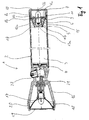
- Die Erfindung wird im folgenden an Hand eines in Figuren dargestellten Ausführungsbeispiels erläutert. Dabei zeigt:
- Figur 1
- Querschnitt einer erfindungsgemäßen Taschenlampe
- Die Taschenlampe 1 weist ein Batteriegehäuse 2 auf, in das eine dreizellige wieder aufladbare Taschenlampenbatterie 3 eingelegt ist. Der Pluspol der Taschenlampenbatterie 3 ist mit einem Plusleitermittel 4 in elektrischem Kontakt. Der Minuspol der Taschenlampenbatterie 3 ist mit einer Kontaktfeder 5 in elektrischem Kontakt.
- Das Batteriegehäuse 2 weist eine Gehäuseöffnung 6 auf, durch die die Taschenlampenbatterie 3 einführbar und herausnehmbar ist. Das Batteriegehäuse 2 weist im Bereich der Gehäuseöffnung 6 ein Innengewinde auf. Das Innengewinde wirkt mit einem Außengewinde einer Verschlußkappe 7 zusammen. Die aufgeschraubte Verschlußkappe 7 ist in Längsrichtung des Batteriegehäuses 2 im wesentlichen zylindrisch ausgebildet und weist eine zylindrische Kappeninnenwandung 8a, 8b auf. Die Verschlußkappe 7 weist eine Öffnungsseite 9 und eine parallel gegenüberliegende Kappenseite 10 auf. Die Kappenseite 10 ist vollständig geschlossen. Das Außengewinde ist im Bereich der Öffnungsseite 9 der Verschlußkappe 7 angeordnet. Die zylindrische Kappeninnenwandung 8a, 8b weist kappenseitig einen ersten Durchmesser 8a auf, an sie schließt sich öffnungsseitig eine Kappeninnenwandung mit einem zweiten etwas größeren Durchmesser 8b an. Der Übergang von der Kappeninnenwandung mit dem ersten Durchmesser 8a zur Kappeninnenwandung mit dem zweiten Durchmesser 8b bildet eine Auflage 11 aus. Auf der Auflage 11 liegen Haltemittel 12a, 12b für eine Ersatzglühbirne 13 auf. Die Haltemittel bestehen aus einer ersten 12a und einer zweiten Lochscheibe 12b, die einen gleichen Durchmesser und einen gleichen Lochdurchmesser haben. Die erste Lochscheibe 12a ist öffnungsseitig parallel zur zweiten Lochscheiben 12b, die direkt auf der Auflage 11 liegt, angeordnet.
- Die Ersatzglühbirne 13 hat ein erstes Ende 13a, das einen Lampenpol hat und ein zweites Ende 13b, das eine von einer Glasbirne umgebende Glühwendel aufweist. Zwischen dem ersten Ende 13a und dem zweiten Ende 13b der Ersatzglühbirne ist ein umlaufender Kragen 14 ausgebildet. Der Außendurchmesser des Kragens 14 ist größer als der Lochdurchmesser der Lochscheiben 12a, 12b. Die Ersatzglühbirne 13 kann somit am Kragen 14 zwischen der ersten 12a und der zweiten Lochscheibe 12b festgehalten werden. Der Abstand zwischen der zweiten Lochscheibe 12b und der Kappenseite 10 der Verschlußkappe 7 ist groß genug, um das zweite Ende 13b der Ersatzglühbirne 13 aufzunehmen.
- Öffnungsseitig schließt sich an die erste Lochscheibe 12a die Kontaktfeder 5 an. Die Kontaktfeder 5 ist hier als sich öffnungsseitig konisch verjüngende Spiralfeder ausgebildet. Die Spiralfeder 5 ist gleichzeitig Minusleitermittel der Taschenlampe 1. Sie weist ein öffnungsseitiges Ende 5a und ein kappenseitiges Ende 5b auf. Das öffnungsseitige Ende 5a hat einen geringeren Durchmesser als das kappenseitige Ende 5b. Das kappenseitige Ende 5b der Spiralfeder ist unter leichtem Zusammendrücken der Spiralfeder 5 in die Verschlußkappe 7 im Bereich der Kappeninnenwandung mit dem zweiten Durchmesser 8b einspannbar. Die in die Verschlußkappe 7 eingespannte Spiralfeder 5 hält die erste 8a und zweite Lochscheibe 8b fest an die Auflage 11 gedrückt. Die Ersatzglühbirne 13 ist somit durch ihren Kragen 14 auch in der Verschlußkappe 7 fixiert.
- Bei aufgeschraubter Verschlußkappe 7 und eingelegter Taschenlampenbatterie 3 ist die Spiralfeder 5 leicht in Richtung Verschlußkappe 7 zusammengedrückt. Die Drucklagerung der Taschenlampenbatterie 3 verhindert ein Hin- und Herrutschen der Taschenlampenbatterie 3. Das öffnungsseitige Ende 9 der Verschlußkappe 7 erweitert sich öffnungsseitig konisch in einem Winkel von etwa 45°, um ein Einspannen des kappenseitigen Endes 5b der Spiralfeder zu erleichtern. Die Verschlußkappe 7 umläuft kappenseitig des Außengewindes ein O-Ring aus Gummi.
- Das erste Ende 13a der Ersatzglühbirne 13 ist von einer Buchse 15 umgeben. Die Buchse 15 besteht aus festem Kunststoff. Die Buchse 15 weist ein kappenseitiges Ende 15a auf, das an der ersten Lochscheibe 8b anschlägt und ein öffnungsseitiges Ende 15b, das in Längsrichtung in Höhe des ersten Endes 13a der Ersatzglühbirne 13 mit dieser abschließt.
- Grundsätzlich wäre es denkbar, daß durch plötzliche Bewegungen der Taschenlampe 1 die Trägheit der Taschenlampenbatterie 3 eine Verformung der Spiralfeder 5 in Richtung der Verschlußkappe 7 über das erste Ende 13a der Ersatzglühbirne 13 hinaus bewirken könnte. Die Spiralfeder 5 ist mit genügend hohem Kraftaufwand prinzipiell fast in eine Ebene zusammendrückbar. Die Buchse 15 schützt das erste Ende 13a der Ersatzglühbirne 13 in dem es Stöße der Taschenlampenbatterie 3 abfängt und über die erste Lochscheibe 8b in die Verschlußkappe 7 leitet. Die Buchse 15 verhindert einen direkten Stoßkontakt zwischen Batterieminuspol und dem erstem Ende 13a der Ersatzglühbirne 13.
- Die Taschenlampe 1 weist an dem der Verschlußkappe 7 gegenüberliegenden Ende den Taschenlampenkopf 16 auf. Der Taschenlampenkopf 16 weist eine etwa mittig gehaltene Glühbirne 17 auf, die von einem parabolischen Reflektor 18 umgeben ist, der am Kopfende von einer Linse 19 abgeschlossen wird. Die Glühbirne 17 wird mittels einer Fassung am Taschenlampenkopf 16 gehalten. Die Linse 19 und der Reflektor 18 sind fest mit einem abschraubbaren Abschnitt 20 des Taschenlampenkopfes verbunden. Der Kragen der Glühbirne 17 bildet einen Kontakt, der dem Batteriegehäuse zugewandte Pol der Glühbirne 17 bildet einen anderen Kontakt der Glühbirne 17 aus. Der andere Kontakt der Glühbirne 17 ist über eine Drahtfeder 21 mit einem Schalter 22 elektrisch verbunden. Der Schalter 22 ist wiederum elektrisch mit dem Plusleitermittel 4 verbunden.
Claims (8)
- Taschenlampe mit- einem Batteriegehäuse (2), mit einer Gehäuseöffnung (6) zur Aufnahme von Taschenlampenbatterien (3),- einer Verschlusskappe (7) für die Gehäuseöffnung (6), mit einer Öffnungsseite (9) und einer gegenüberliegenden Kappenseite (10),- einer Ersatzleuchte (13), die zwischen einem ersten (13a) und einem zweiten Ende (13b) eine Fassung hat, die einen wenigstens teilweise umlaufenden Kragen (14) aufweist,- in der Verschlußkappe (7) angeordneten Haltemitteln (12a, 12b) für die Ersatzleuchte (13), die derart ausgeformt sind, daß das erstes Ende (13a) der Ersatzleuchte (13) von den Haltemitteln (12a, 12b) öffnungsseitig absteht,- wenigstens einer öffnungsseitig von den Haltemitteln (12a, 12b) abstehenden Kontaktfeder (5), die in Richtung Kappenseite (10) zur Drucklagerung der Taschenlampenbatterien (3) elastisch verformbar ist,- einem am ersten Ende (13a) der Ersatzleuchte (13) angeordneten festen Schutzelement (15), das öffnungsseitig wenigstens bis zum ersten Ende (13a) der Ersatzleuchte (13) absteht,- einer Auflage (11) an einer Kappeninnenwandung (8a, 8b) der Verschlusskappe (7), und- einer ersten Lochscheibe (12a) zum Hindurchschieben des ersten Endes (13a) der Ersatzleuchte als ein Haltemittel (12a, 12b), dadurch gekennzeichnet, dass als ein weiteres Haltemittel (12a, 12b) eine zweite Lochscheibe (12b) zum Hindurchschieben des zweiten Endes (13b) der Ersatzleuchte vorgesehen ist, der Durchmesser der zweiten Lochscheibe (12b) zum Zusammenwirken mit der Auflage (11) ausgelegt ist, und dass die Durchmesser der Löcher der ersten (12a) und zweiten Lochscheibe (12b) kleiner als der Durchmesser des Kragens (14) der Ersatzleuchte (13) sind.
- Taschenlampe nach Anspruch 1, dadurch gekennzeichnet, daß die Kappeninnenwandung (8a, 8b) im Wesentlichen zylindrisch ausgebildet ist.
- Taschenlampe nach Anspruch 1 oder 2, dadurch gekennzeichnet, daß die Kappeninnenwandung einen ersten (8a) und einen zweiten (8b) größeren Durchmesser aufweist und die Auflage (11) durch den Übergang von der Kappeninnenwandung mit dem ersten Durchmesser (8a) zur Kappeninnenwandung mit dem zweiten Durchmesser (8b) ausgeformt wird.
- Taschenlampe nach einem der vorgenannten Ansprüche, dadurch gekennzeichnet, daß die wenigstens eine Kontaktfeder eine sich öffnungsseitig verjüngende Spiralfeder (5) mit einem kappenseitigen Ende (5b) aufweist und das entspannte kappenseitige Ende (5b) einen etwas größeren Durchmesser als den ersten Durchmesser (8b) der Kappeninnenwandung aufweist.
- Taschenlampe nach einem der vorgenannten Ansprüche, dadurch gekennzeichnet, daß das Schutzelement als Buchse (15) mit einem kappenseitigen Ende (15a) und einem öffnungsseitigen Ende (15b) ausgeformt ist, die über das erste Ende (13a) der Leuchte führbar ist und deren kappenseitiges Ende (15a) zum öffnungsseitigen Anschlag an der ersten Lochscheibe (12a) bestimmt ist und deren öffnungsseitigs Ende (15b) über das erste Ende (13a) der Ersatzleuchte hinaus öffnungsseitig absteht.
- Taschenlampe nach Anspruch 5, dadurch gekennzeichnet, daß die Buchse (15) innenwandig an dem kappenseitigen Ende (15a) ausgeformte Vorsprünge aufweist.
- Taschenlampe nach einem der vorgenannten Ansprüche, dadurch gekennzeichnet, daß die Verschlußkappe (7) ein Außengewinde und die Gehäuseöffnung (6) ein korrespondierendes Innengewinde aufweist und ein O-Ring am kappenseitigen Ende des Außengewindes vorgesehen ist.
- Taschenlampe nach einem der vorgenannten Ansprüche, dadurch gekennzeichnet, daß sich das öffnungsseitige Ende (9) der Verschlußkappe (7) öffnungsseitig konisch erweitert.
Applications Claiming Priority (3)
| Application Number | Priority Date | Filing Date | Title |
|---|---|---|---|
| DE10139376A DE10139376A1 (de) | 2001-08-20 | 2001-08-20 | Taschenlampe mit Ersatzglühbirne |
| DE10039376 | 2001-08-20 | ||
| PCT/IB2002/000239 WO2003016780A1 (de) | 2001-08-20 | 2002-01-28 | Taschenlampe mit ersatzglühbirne |
Publications (3)
| Publication Number | Publication Date |
|---|---|
| EP1419344A1 EP1419344A1 (de) | 2004-05-19 |
| EP1419344A4 EP1419344A4 (de) | 2006-05-31 |
| EP1419344B1 true EP1419344B1 (de) | 2008-06-18 |
Family
ID=7695060
Family Applications (1)
| Application Number | Title | Priority Date | Filing Date |
|---|---|---|---|
| EP02794824A Expired - Lifetime EP1419344B1 (de) | 2001-08-20 | 2002-01-28 | Taschenlampe mit ersatzglühbirne |
Country Status (9)
| Country | Link |
|---|---|
| US (1) | US20040196655A1 (de) |
| EP (1) | EP1419344B1 (de) |
| AT (1) | ATE398752T1 (de) |
| CA (1) | CA2435670C (de) |
| DE (2) | DE10139376A1 (de) |
| DK (1) | DK1419344T3 (de) |
| ES (1) | ES2307818T3 (de) |
| PT (1) | PT1419344E (de) |
| WO (1) | WO2003016780A1 (de) |
Family Cites Families (16)
| Publication number | Priority date | Publication date | Assignee | Title |
|---|---|---|---|---|
| US1661784A (en) * | 1928-03-06 | And john h | ||
| US2599253A (en) * | 1946-08-29 | 1952-06-03 | Jules P Gits | Angular head flashlight casing, including a readily attachable lamp contact means |
| US3829676A (en) * | 1973-08-07 | 1974-08-13 | Kel Lite Industries | Rechargeable flashlight |
| US4325107A (en) * | 1980-01-29 | 1982-04-13 | Macleod Richard H | Rechargeable flashlight |
| US5349506A (en) * | 1984-09-06 | 1994-09-20 | Mag Instrument, Inc. | Miniature flashlight |
| US5003440A (en) * | 1989-05-17 | 1991-03-26 | Mag Instrument, Inc. | Tailcap insert |
| GB2239937B (en) * | 1990-01-16 | 1993-02-17 | Howard Wang | Flashlight |
| US6135611A (en) * | 1991-06-21 | 2000-10-24 | Mag Instrument, Inc. | Miniature flashlight |
| US5833354A (en) * | 1992-04-10 | 1998-11-10 | Mag Instrument, Inc. | Flashlight and bulb holder therefor |
| CN2132915Y (zh) * | 1992-05-30 | 1993-05-12 | 萧水树 | 手电筒聚焦开关 |
| US5432689A (en) * | 1993-01-13 | 1995-07-11 | Streamlight, Inc. | Flashlight and recharging system therefor |
| GB2319331B (en) * | 1996-11-13 | 1998-12-23 | Si Fu Chiu | Electric torch |
| JP3253578B2 (ja) | 1997-12-15 | 2002-02-04 | 日本精工株式会社 | 電動式パワーステアリング装置 |
| JP3376869B2 (ja) | 1997-05-29 | 2003-02-10 | 日本精工株式会社 | 電動式パワーステアリング装置 |
| CN2410523Y (zh) * | 2000-03-31 | 2000-12-13 | 岑显亮 | 旋转式开关防水手电筒 |
| US6722772B2 (en) * | 2001-08-16 | 2004-04-20 | Mag Instrument, Inc. | Flashlight and combination for use in aligning flashlight lamp bulbs |
-
2001
- 2001-08-20 DE DE10139376A patent/DE10139376A1/de not_active Withdrawn
-
2002
- 2002-01-28 AT AT02794824T patent/ATE398752T1/de active
- 2002-01-28 WO PCT/IB2002/000239 patent/WO2003016780A1/de not_active Ceased
- 2002-01-28 EP EP02794824A patent/EP1419344B1/de not_active Expired - Lifetime
- 2002-01-28 CA CA002435670A patent/CA2435670C/en not_active Expired - Fee Related
- 2002-01-28 US US10/487,371 patent/US20040196655A1/en not_active Abandoned
- 2002-01-28 PT PT02794824T patent/PT1419344E/pt unknown
- 2002-01-28 DK DK02794824T patent/DK1419344T3/da active
- 2002-01-28 ES ES02794824T patent/ES2307818T3/es not_active Expired - Lifetime
- 2002-01-28 DE DE50212388T patent/DE50212388D1/de not_active Expired - Lifetime
Also Published As
| Publication number | Publication date |
|---|---|
| PT1419344E (pt) | 2008-09-11 |
| DE10139376A1 (de) | 2003-03-13 |
| HK1067689A1 (zh) | 2005-04-15 |
| US20040196655A1 (en) | 2004-10-07 |
| ATE398752T1 (de) | 2008-07-15 |
| DK1419344T3 (da) | 2008-10-13 |
| CA2435670C (en) | 2008-07-29 |
| WO2003016780A1 (de) | 2003-02-27 |
| DE50212388D1 (de) | 2008-07-31 |
| ES2307818T3 (es) | 2008-12-01 |
| EP1419344A4 (de) | 2006-05-31 |
| EP1419344A1 (de) | 2004-05-19 |
| CA2435670A1 (en) | 2003-02-27 |
Similar Documents
| Publication | Publication Date | Title |
|---|---|---|
| DE68914023T2 (de) | Taschenlampe mit Einzelbatterie. | |
| EP2405179B1 (de) | Taschenlampe | |
| DE29905728U1 (de) | Drückbare Leuchtvorrichtung | |
| DE102007054930A1 (de) | Lampenfassung | |
| DE20300012U1 (de) | Karabiner | |
| DE2800936A1 (de) | Schalter, insbesondere fuer eine taschenlampe | |
| DE20115257U1 (de) | Druckbetätigbare Batterielampe | |
| DE29820081U1 (de) | Taschenlampe, insbesondere Gehäuseteil | |
| DE10025000C1 (de) | Steckerleuchte, insbesondere als Fahrzeuginnenleuchte | |
| EP1419344B1 (de) | Taschenlampe mit ersatzglühbirne | |
| DE69300225T2 (de) | Gehäuse mit flexiblem Befestigungsring. | |
| EP1914471A2 (de) | Batteriebetriebene Leuchtenanordnung, insbesondere nach Art einer Kerze | |
| DE3615059C2 (de) | Beleuchtungseinheit für elektrische Schalter | |
| DE202008015047U1 (de) | Elektrische Lampe | |
| DE202009005472U1 (de) | Lampenfassung | |
| DE2062470A1 (de) | Taschenlampe mit einer Aufnahme fur die Birne | |
| DE102004054306A1 (de) | Beleuchtungsvorrichtung | |
| DE19952132A1 (de) | Elektrische Lampenfassung | |
| DE9308847U1 (de) | Taschenlampe mit veränderbarer Lichtstrahlbündelung | |
| AT223700B (de) | Batteriebetriebene Taschen- oder Handleuchte | |
| DE102024124565A1 (de) | Leuchte | |
| DE102024104522A1 (de) | Anordnungselement für LED und lichtlenkendes Bauelement | |
| DE202010009945U1 (de) | Taschenlampe | |
| DE1764349A1 (de) | Bauteil zur Befestigung des Leuchtenkopfes und zur Aufnahme der Gluehlampe einer Taschenleuchte | |
| DE29502955U1 (de) | Handlampe |
Legal Events
| Date | Code | Title | Description |
|---|---|---|---|
| PUAI | Public reference made under article 153(3) epc to a published international application that has entered the european phase |
Free format text: ORIGINAL CODE: 0009012 |
|
| 17P | Request for examination filed |
Effective date: 20030414 |
|
| AK | Designated contracting states |
Kind code of ref document: A1 Designated state(s): AT BE CH CY DE DK ES FI FR GB GR IE IT LI LU MC NL PT SE TR |
|
| AX | Request for extension of the european patent |
Extension state: AL LT LV MK RO SI |
|
| REG | Reference to a national code |
Ref country code: HK Ref legal event code: DE Ref document number: 1067689 Country of ref document: HK |
|
| A4 | Supplementary search report drawn up and despatched |
Effective date: 20060420 |
|
| 17Q | First examination report despatched |
Effective date: 20060811 |
|
| GRAP | Despatch of communication of intention to grant a patent |
Free format text: ORIGINAL CODE: EPIDOSNIGR1 |
|
| GRAS | Grant fee paid |
Free format text: ORIGINAL CODE: EPIDOSNIGR3 |
|
| GRAA | (expected) grant |
Free format text: ORIGINAL CODE: 0009210 |
|
| AK | Designated contracting states |
Kind code of ref document: B1 Designated state(s): AT BE CH CY DE DK ES FI FR GB GR IE IT LI LU MC NL PT SE TR |
|
| REG | Reference to a national code |
Ref country code: GB Ref legal event code: FG4D Free format text: NOT ENGLISH |
|
| REF | Corresponds to: |
Ref document number: 50212388 Country of ref document: DE Date of ref document: 20080731 Kind code of ref document: P |
|
| REG | Reference to a national code |
Ref country code: CH Ref legal event code: EP |
|
| REG | Reference to a national code |
Ref country code: IE Ref legal event code: FG4D Free format text: LANGUAGE OF EP DOCUMENT: GERMAN |
|
| REG | Reference to a national code |
Ref country code: PT Ref legal event code: SC4A Free format text: AVAILABILITY OF NATIONAL TRANSLATION Effective date: 20080901 |
|
| REG | Reference to a national code |
Ref country code: SE Ref legal event code: TRGR |
|
| REG | Reference to a national code |
Ref country code: DK Ref legal event code: T3 Ref country code: GR Ref legal event code: EP Ref document number: 20080402386 Country of ref document: GR |
|
| REG | Reference to a national code |
Ref country code: ES Ref legal event code: FG2A Ref document number: 2307818 Country of ref document: ES Kind code of ref document: T3 |
|
| REG | Reference to a national code |
Ref country code: IE Ref legal event code: FD4D |
|
| PLBE | No opposition filed within time limit |
Free format text: ORIGINAL CODE: 0009261 |
|
| STAA | Information on the status of an ep patent application or granted ep patent |
Free format text: STATUS: NO OPPOSITION FILED WITHIN TIME LIMIT |
|
| PG25 | Lapsed in a contracting state [announced via postgrant information from national office to epo] |
Ref country code: IE Free format text: LAPSE BECAUSE OF FAILURE TO SUBMIT A TRANSLATION OF THE DESCRIPTION OR TO PAY THE FEE WITHIN THE PRESCRIBED TIME-LIMIT Effective date: 20080618 |
|
| 26N | No opposition filed |
Effective date: 20090319 |
|
| REG | Reference to a national code |
Ref country code: HK Ref legal event code: GR Ref document number: 1067689 Country of ref document: HK |
|
| PG25 | Lapsed in a contracting state [announced via postgrant information from national office to epo] |
Ref country code: MC Free format text: LAPSE BECAUSE OF NON-PAYMENT OF DUE FEES Effective date: 20090131 |
|
| REG | Reference to a national code |
Ref country code: CH Ref legal event code: PL |
|
| PG25 | Lapsed in a contracting state [announced via postgrant information from national office to epo] |
Ref country code: LI Free format text: LAPSE BECAUSE OF NON-PAYMENT OF DUE FEES Effective date: 20090131 Ref country code: CH Free format text: LAPSE BECAUSE OF NON-PAYMENT OF DUE FEES Effective date: 20090131 |
|
| PG25 | Lapsed in a contracting state [announced via postgrant information from national office to epo] |
Ref country code: LU Free format text: LAPSE BECAUSE OF NON-PAYMENT OF DUE FEES Effective date: 20090128 |
|
| PGFP | Annual fee paid to national office [announced via postgrant information from national office to epo] |
Ref country code: DK Payment date: 20110112 Year of fee payment: 10 |
|
| PGFP | Annual fee paid to national office [announced via postgrant information from national office to epo] |
Ref country code: DE Payment date: 20110117 Year of fee payment: 10 Ref country code: FR Payment date: 20110126 Year of fee payment: 10 Ref country code: FI Payment date: 20110126 Year of fee payment: 10 Ref country code: AT Payment date: 20110126 Year of fee payment: 10 Ref country code: NL Payment date: 20110131 Year of fee payment: 10 Ref country code: IT Payment date: 20110118 Year of fee payment: 10 Ref country code: SE Payment date: 20110124 Year of fee payment: 10 Ref country code: PT Payment date: 20110118 Year of fee payment: 10 |
|
| PGFP | Annual fee paid to national office [announced via postgrant information from national office to epo] |
Ref country code: GR Payment date: 20110128 Year of fee payment: 10 |
|
| PGFP | Annual fee paid to national office [announced via postgrant information from national office to epo] |
Ref country code: ES Payment date: 20110117 Year of fee payment: 10 Ref country code: BE Payment date: 20110204 Year of fee payment: 10 Ref country code: GB Payment date: 20110126 Year of fee payment: 10 |
|
| PG25 | Lapsed in a contracting state [announced via postgrant information from national office to epo] |
Ref country code: TR Free format text: LAPSE BECAUSE OF FAILURE TO SUBMIT A TRANSLATION OF THE DESCRIPTION OR TO PAY THE FEE WITHIN THE PRESCRIBED TIME-LIMIT Effective date: 20080618 |
|
| PG25 | Lapsed in a contracting state [announced via postgrant information from national office to epo] |
Ref country code: CY Free format text: LAPSE BECAUSE OF FAILURE TO SUBMIT A TRANSLATION OF THE DESCRIPTION OR TO PAY THE FEE WITHIN THE PRESCRIBED TIME-LIMIT Effective date: 20080618 |
|
| BERE | Be: lapsed |
Owner name: CREATIVE TECHNOLOGY HONG KONG LTD Effective date: 20120131 |
|
| REG | Reference to a national code |
Ref country code: PT Ref legal event code: MM4A Free format text: LAPSE DUE TO NON-PAYMENT OF FEES Effective date: 20120730 |
|
| REG | Reference to a national code |
Ref country code: NL Ref legal event code: V1 Effective date: 20120801 |
|
| REG | Reference to a national code |
Ref country code: SE Ref legal event code: EUG |
|
| REG | Reference to a national code |
Ref country code: DK Ref legal event code: EBP |
|
| REG | Reference to a national code |
Ref country code: GR Ref legal event code: ML Ref document number: 20080402386 Country of ref document: GR Effective date: 20120802 |
|
| GBPC | Gb: european patent ceased through non-payment of renewal fee |
Effective date: 20120128 |
|
| REG | Reference to a national code |
Ref country code: FR Ref legal event code: ST Effective date: 20120928 |
|
| PG25 | Lapsed in a contracting state [announced via postgrant information from national office to epo] |
Ref country code: FI Free format text: LAPSE BECAUSE OF NON-PAYMENT OF DUE FEES Effective date: 20120128 Ref country code: DE Free format text: LAPSE BECAUSE OF NON-PAYMENT OF DUE FEES Effective date: 20120801 Ref country code: SE Free format text: LAPSE BECAUSE OF NON-PAYMENT OF DUE FEES Effective date: 20120129 Ref country code: GB Free format text: LAPSE BECAUSE OF NON-PAYMENT OF DUE FEES Effective date: 20120128 |
|
| REG | Reference to a national code |
Ref country code: DE Ref legal event code: R119 Ref document number: 50212388 Country of ref document: DE Effective date: 20120801 |
|
| PG25 | Lapsed in a contracting state [announced via postgrant information from national office to epo] |
Ref country code: GR Free format text: LAPSE BECAUSE OF NON-PAYMENT OF DUE FEES Effective date: 20120802 Ref country code: PT Free format text: LAPSE BECAUSE OF NON-PAYMENT OF DUE FEES Effective date: 20120730 Ref country code: IT Free format text: LAPSE BECAUSE OF NON-PAYMENT OF DUE FEES Effective date: 20120128 |
|
| REG | Reference to a national code |
Ref country code: AT Ref legal event code: MM01 Ref document number: 398752 Country of ref document: AT Kind code of ref document: T Effective date: 20120128 |
|
| PG25 | Lapsed in a contracting state [announced via postgrant information from national office to epo] |
Ref country code: BE Free format text: LAPSE BECAUSE OF NON-PAYMENT OF DUE FEES Effective date: 20120131 Ref country code: FR Free format text: LAPSE BECAUSE OF NON-PAYMENT OF DUE FEES Effective date: 20120131 |
|
| PG25 | Lapsed in a contracting state [announced via postgrant information from national office to epo] |
Ref country code: NL Free format text: LAPSE BECAUSE OF NON-PAYMENT OF DUE FEES Effective date: 20120801 Ref country code: AT Free format text: LAPSE BECAUSE OF NON-PAYMENT OF DUE FEES Effective date: 20120128 Ref country code: DK Free format text: LAPSE BECAUSE OF NON-PAYMENT OF DUE FEES Effective date: 20120131 |
|
| REG | Reference to a national code |
Ref country code: ES Ref legal event code: FD2A Effective date: 20130708 |
|
| PG25 | Lapsed in a contracting state [announced via postgrant information from national office to epo] |
Ref country code: ES Free format text: LAPSE BECAUSE OF NON-PAYMENT OF DUE FEES Effective date: 20120129 |