EP1419376B1 - Manipulation de substances a analyser au moyen de champs electriques - Google Patents
Manipulation de substances a analyser au moyen de champs electriques Download PDFInfo
- Publication number
- EP1419376B1 EP1419376B1 EP02766066A EP02766066A EP1419376B1 EP 1419376 B1 EP1419376 B1 EP 1419376B1 EP 02766066 A EP02766066 A EP 02766066A EP 02766066 A EP02766066 A EP 02766066A EP 1419376 B1 EP1419376 B1 EP 1419376B1
- Authority
- EP
- European Patent Office
- Prior art keywords
- members
- electrically
- conductive members
- analyte
- end regions
- Prior art date
- Legal status (The legal status is an assumption and is not a legal conclusion. Google has not performed a legal analysis and makes no representation as to the accuracy of the status listed.)
- Expired - Lifetime
Links
- 230000005684 electric field Effects 0.000 title claims abstract description 30
- 239000012491 analyte Substances 0.000 claims abstract description 41
- 239000000463 material Substances 0.000 claims description 12
- 230000033001 locomotion Effects 0.000 claims description 6
- 238000004891 communication Methods 0.000 claims description 5
- 229920005989 resin Polymers 0.000 claims description 5
- 239000011347 resin Substances 0.000 claims description 5
- 239000011324 bead Substances 0.000 claims description 3
- 239000008151 electrolyte solution Substances 0.000 claims description 3
- 239000004593 Epoxy Substances 0.000 claims description 2
- 238000007373 indentation Methods 0.000 claims description 2
- 239000011148 porous material Substances 0.000 claims description 2
- 238000000034 method Methods 0.000 abstract description 8
- 238000000746 purification Methods 0.000 abstract description 4
- 239000000523 sample Substances 0.000 description 15
- 102000039446 nucleic acids Human genes 0.000 description 14
- 108020004707 nucleic acids Proteins 0.000 description 14
- 150000007523 nucleic acids Chemical class 0.000 description 14
- 230000002209 hydrophobic effect Effects 0.000 description 6
- 239000002245 particle Substances 0.000 description 6
- 238000009396 hybridization Methods 0.000 description 5
- 102000040430 polynucleotide Human genes 0.000 description 5
- 108091033319 polynucleotide Proteins 0.000 description 5
- 239000002157 polynucleotide Substances 0.000 description 5
- 238000000926 separation method Methods 0.000 description 5
- 238000000576 coating method Methods 0.000 description 4
- 230000000295 complement effect Effects 0.000 description 4
- 239000007788 liquid Substances 0.000 description 4
- 150000003839 salts Chemical class 0.000 description 4
- 239000000758 substrate Substances 0.000 description 4
- 238000004458 analytical method Methods 0.000 description 3
- 239000008364 bulk solution Substances 0.000 description 3
- 238000006243 chemical reaction Methods 0.000 description 3
- 239000012141 concentrate Substances 0.000 description 3
- 239000004020 conductor Substances 0.000 description 3
- -1 e.g. Proteins 0.000 description 3
- 238000012986 modification Methods 0.000 description 3
- 230000004048 modification Effects 0.000 description 3
- 241000894007 species Species 0.000 description 3
- 239000000853 adhesive Substances 0.000 description 2
- 230000001070 adhesive effect Effects 0.000 description 2
- 238000002306 biochemical method Methods 0.000 description 2
- 230000015572 biosynthetic process Effects 0.000 description 2
- 238000005251 capillar electrophoresis Methods 0.000 description 2
- 210000004027 cell Anatomy 0.000 description 2
- 239000013592 cell lysate Substances 0.000 description 2
- 238000011033 desalting Methods 0.000 description 2
- 230000000694 effects Effects 0.000 description 2
- 239000012530 fluid Substances 0.000 description 2
- 238000002347 injection Methods 0.000 description 2
- 239000007924 injection Substances 0.000 description 2
- 239000000203 mixture Substances 0.000 description 2
- 239000012811 non-conductive material Substances 0.000 description 2
- 238000007899 nucleic acid hybridization Methods 0.000 description 2
- 230000000737 periodic effect Effects 0.000 description 2
- BASFCYQUMIYNBI-UHFFFAOYSA-N platinum Chemical compound [Pt] BASFCYQUMIYNBI-UHFFFAOYSA-N 0.000 description 2
- 239000007787 solid Substances 0.000 description 2
- 239000000126 substance Substances 0.000 description 2
- 229920000936 Agarose Polymers 0.000 description 1
- RYGMFSIKBFXOCR-UHFFFAOYSA-N Copper Chemical compound [Cu] RYGMFSIKBFXOCR-UHFFFAOYSA-N 0.000 description 1
- 108010010803 Gelatin Proteins 0.000 description 1
- 229920000557 Nafion® Polymers 0.000 description 1
- 239000004677 Nylon Substances 0.000 description 1
- 239000004698 Polyethylene Substances 0.000 description 1
- 239000004642 Polyimide Substances 0.000 description 1
- 239000004743 Polypropylene Substances 0.000 description 1
- 239000004793 Polystyrene Substances 0.000 description 1
- 229920002472 Starch Polymers 0.000 description 1
- 239000004809 Teflon Substances 0.000 description 1
- 229920006362 Teflon® Polymers 0.000 description 1
- 241000700605 Viruses Species 0.000 description 1
- XAGFODPZIPBFFR-UHFFFAOYSA-N aluminium Chemical compound [Al] XAGFODPZIPBFFR-UHFFFAOYSA-N 0.000 description 1
- 229910052782 aluminium Inorganic materials 0.000 description 1
- 239000000427 antigen Substances 0.000 description 1
- 239000012736 aqueous medium Substances 0.000 description 1
- 239000007864 aqueous solution Substances 0.000 description 1
- 238000003491 array Methods 0.000 description 1
- 239000012620 biological material Substances 0.000 description 1
- 239000007853 buffer solution Substances 0.000 description 1
- 235000014633 carbohydrates Nutrition 0.000 description 1
- 150000001720 carbohydrates Chemical class 0.000 description 1
- 239000000919 ceramic Substances 0.000 description 1
- 238000013375 chromatographic separation Methods 0.000 description 1
- 239000002299 complementary DNA Substances 0.000 description 1
- 239000012468 concentrated sample Substances 0.000 description 1
- 229910052802 copper Inorganic materials 0.000 description 1
- 239000010949 copper Substances 0.000 description 1
- 230000008021 deposition Effects 0.000 description 1
- 239000000975 dye Substances 0.000 description 1
- 239000012799 electrically-conductive coating Substances 0.000 description 1
- 238000001962 electrophoresis Methods 0.000 description 1
- 238000005516 engineering process Methods 0.000 description 1
- 229920000159 gelatin Polymers 0.000 description 1
- 239000008273 gelatin Substances 0.000 description 1
- 235000019322 gelatine Nutrition 0.000 description 1
- 235000011852 gelatine desserts Nutrition 0.000 description 1
- 229920001600 hydrophobic polymer Polymers 0.000 description 1
- HTXDPTMKBJXEOW-UHFFFAOYSA-N iridium(IV) oxide Inorganic materials O=[Ir]=O HTXDPTMKBJXEOW-UHFFFAOYSA-N 0.000 description 1
- 239000012469 less concentrated sample Substances 0.000 description 1
- 239000003446 ligand Substances 0.000 description 1
- 230000004807 localization Effects 0.000 description 1
- 239000000314 lubricant Substances 0.000 description 1
- 230000000873 masking effect Effects 0.000 description 1
- 239000002609 medium Substances 0.000 description 1
- 239000012528 membrane Substances 0.000 description 1
- 239000007769 metal material Substances 0.000 description 1
- 238000001471 micro-filtration Methods 0.000 description 1
- 230000007935 neutral effect Effects 0.000 description 1
- 229910021508 nickel(II) hydroxide Inorganic materials 0.000 description 1
- 229920001778 nylon Polymers 0.000 description 1
- 230000003287 optical effect Effects 0.000 description 1
- 210000003463 organelle Anatomy 0.000 description 1
- 229920000620 organic polymer Polymers 0.000 description 1
- 239000003973 paint Substances 0.000 description 1
- 229910052763 palladium Inorganic materials 0.000 description 1
- 238000005192 partition Methods 0.000 description 1
- 125000002467 phosphate group Chemical group [H]OP(=O)(O[H])O[*] 0.000 description 1
- 239000004033 plastic Substances 0.000 description 1
- 229920003023 plastic Polymers 0.000 description 1
- 229910052697 platinum Inorganic materials 0.000 description 1
- 230000010287 polarization Effects 0.000 description 1
- 229920000573 polyethylene Polymers 0.000 description 1
- 229920001721 polyimide Polymers 0.000 description 1
- 229920001155 polypropylene Polymers 0.000 description 1
- 229920002223 polystyrene Polymers 0.000 description 1
- 108090000623 proteins and genes Proteins 0.000 description 1
- 102000004169 proteins and genes Human genes 0.000 description 1
- 239000012521 purified sample Substances 0.000 description 1
- 238000010079 rubber tapping Methods 0.000 description 1
- 235000019698 starch Nutrition 0.000 description 1
- 239000008107 starch Substances 0.000 description 1
- 239000000725 suspension Substances 0.000 description 1
Images
Classifications
-
- G—PHYSICS
- G01—MEASURING; TESTING
- G01N—INVESTIGATING OR ANALYSING MATERIALS BY DETERMINING THEIR CHEMICAL OR PHYSICAL PROPERTIES
- G01N27/00—Investigating or analysing materials by the use of electric, electrochemical, or magnetic means
- G01N27/26—Investigating or analysing materials by the use of electric, electrochemical, or magnetic means by investigating electrochemical variables; by using electrolysis or electrophoresis
- G01N27/416—Systems
- G01N27/447—Systems using electrophoresis
- G01N27/44704—Details; Accessories
-
- B—PERFORMING OPERATIONS; TRANSPORTING
- B01—PHYSICAL OR CHEMICAL PROCESSES OR APPARATUS IN GENERAL
- B01L—CHEMICAL OR PHYSICAL LABORATORY APPARATUS FOR GENERAL USE
- B01L3/00—Containers or dishes for laboratory use, e.g. laboratory glassware; Droppers
- B01L3/50—Containers for the purpose of retaining a material to be analysed, e.g. test tubes
- B01L3/502—Containers for the purpose of retaining a material to be analysed, e.g. test tubes with fluid transport, e.g. in multi-compartment structures
-
- B—PERFORMING OPERATIONS; TRANSPORTING
- B03—SEPARATION OF SOLID MATERIALS USING LIQUIDS OR USING PNEUMATIC TABLES OR JIGS; MAGNETIC OR ELECTROSTATIC SEPARATION OF SOLID MATERIALS FROM SOLID MATERIALS OR FLUIDS; SEPARATION BY HIGH-VOLTAGE ELECTRIC FIELDS
- B03C—MAGNETIC OR ELECTROSTATIC SEPARATION OF SOLID MATERIALS FROM SOLID MATERIALS OR FLUIDS; SEPARATION BY HIGH-VOLTAGE ELECTRIC FIELDS
- B03C5/00—Separating dispersed particles from liquids by electrostatic effect
- B03C5/02—Separators
- B03C5/022—Non-uniform field separators
- B03C5/026—Non-uniform field separators using open-gradient differential dielectric separation, i.e. using electrodes of special shapes for non-uniform field creation, e.g. Fluid Integrated Circuit [FIC]
-
- G—PHYSICS
- G01—MEASURING; TESTING
- G01N—INVESTIGATING OR ANALYSING MATERIALS BY DETERMINING THEIR CHEMICAL OR PHYSICAL PROPERTIES
- G01N1/00—Sampling; Preparing specimens for investigation
- G01N1/28—Preparing specimens for investigation including physical details of (bio-)chemical methods covered elsewhere, e.g. G01N33/50, C12Q
- G01N1/40—Concentrating samples
-
- G—PHYSICS
- G01—MEASURING; TESTING
- G01N—INVESTIGATING OR ANALYSING MATERIALS BY DETERMINING THEIR CHEMICAL OR PHYSICAL PROPERTIES
- G01N27/00—Investigating or analysing materials by the use of electric, electrochemical, or magnetic means
- G01N27/26—Investigating or analysing materials by the use of electric, electrochemical, or magnetic means by investigating electrochemical variables; by using electrolysis or electrophoresis
- G01N27/416—Systems
- G01N27/447—Systems using electrophoresis
- G01N27/44756—Apparatus specially adapted therefor
-
- B—PERFORMING OPERATIONS; TRANSPORTING
- B01—PHYSICAL OR CHEMICAL PROCESSES OR APPARATUS IN GENERAL
- B01L—CHEMICAL OR PHYSICAL LABORATORY APPARATUS FOR GENERAL USE
- B01L2200/00—Solutions for specific problems relating to chemical or physical laboratory apparatus
- B01L2200/06—Fluid handling related problems
- B01L2200/0631—Purification arrangements, e.g. solid phase extraction [SPE]
-
- B—PERFORMING OPERATIONS; TRANSPORTING
- B01—PHYSICAL OR CHEMICAL PROCESSES OR APPARATUS IN GENERAL
- B01L—CHEMICAL OR PHYSICAL LABORATORY APPARATUS FOR GENERAL USE
- B01L2200/00—Solutions for specific problems relating to chemical or physical laboratory apparatus
- B01L2200/06—Fluid handling related problems
- B01L2200/0647—Handling flowable solids, e.g. microscopic beads, cells, particles
-
- B—PERFORMING OPERATIONS; TRANSPORTING
- B01—PHYSICAL OR CHEMICAL PROCESSES OR APPARATUS IN GENERAL
- B01L—CHEMICAL OR PHYSICAL LABORATORY APPARATUS FOR GENERAL USE
- B01L2300/00—Additional constructional details
- B01L2300/06—Auxiliary integrated devices, integrated components
- B01L2300/0627—Sensor or part of a sensor is integrated
- B01L2300/0645—Electrodes
-
- B—PERFORMING OPERATIONS; TRANSPORTING
- B01—PHYSICAL OR CHEMICAL PROCESSES OR APPARATUS IN GENERAL
- B01L—CHEMICAL OR PHYSICAL LABORATORY APPARATUS FOR GENERAL USE
- B01L2400/00—Moving or stopping fluids
- B01L2400/04—Moving fluids with specific forces or mechanical means
- B01L2400/0403—Moving fluids with specific forces or mechanical means specific forces
- B01L2400/0415—Moving fluids with specific forces or mechanical means specific forces electrical forces, e.g. electrokinetic
-
- G—PHYSICS
- G01—MEASURING; TESTING
- G01N—INVESTIGATING OR ANALYSING MATERIALS BY DETERMINING THEIR CHEMICAL OR PHYSICAL PROPERTIES
- G01N1/00—Sampling; Preparing specimens for investigation
- G01N1/28—Preparing specimens for investigation including physical details of (bio-)chemical methods covered elsewhere, e.g. G01N33/50, C12Q
- G01N1/40—Concentrating samples
- G01N2001/4038—Concentrating samples electric methods, e.g. electromigration, electrophoresis, ionisation
Definitions
- This invention relates to apparatus for the manipulation of analytes using electric fields.
- analyte concentration can enhance chemical reaction rates, rates of mass transfer, and/or detectability, etc.
- methods for controlling the location of at least a portion of a sample or analyte can be important in many chemical and biochemical methods and/or applications.
- small dielectric particles such as biological cells or DNA molecules are suspended in a quantity of liquid within a container.
- a pair of spaced apart electrodes are immersed in the liquid and a coil surrounds the region between the electrodes.
- First and second electric signals are applied to the electrodes and the coil, respectively, to thereby generate substantially orthogonal oscillating electric and magnetic fields which are at the same frequency but approximately ninety degrees out of phase.
- particles having different polarization relaxation frequencies and sizes will migrate at different velocities and thereby sort into various fractions.
- the present invention is directed towards devices for the manipulation (e.g., concentration, purification, capture, trapping, location, transfer, and the like) of polarizable analytes, such as polynucleotides, using one or more electric fields.
- devices for the manipulation e.g., concentration, purification, capture, trapping, location, transfer, and the like
- polarizable analytes such as polynucleotides
- the present invention relates, in part, to a device for purification/concentration of an analyte away from a processor and/or analyzer (e.g., a capillary electrophoresis device, an optical reader, a mass spectrometer, a chromatographic column, a PCR device, etc.).
- a device of the present invention is useful in transferring a purified/concentrated sample to a desired location, such as to a sample-receiving region of such a processor and/or analyzer, and/or to a vessel such as a tube or a well of a multi-well plate.
- the invention makes use of the phenomenon that if a molecule or particle can be polarized, then it can be attracted or repelled from a field gradient.
- the invention is based in part on the discovery that when a polarizable analyte is attracted to a region having an alternating current electrical field gradient, the analyte can become trapped in a concentration zone formed by the alternating electric field.
- Various embodiments of the present invention for example, contemplate polynucleotides, e.g., DNA or RNA, as polarizable molecules of interest, and utilize increasing field gradients to attract such molecules.
- One of the many applications of the present invention is to partition, at least in part, DNA from salts or free dyes.
- the present invention provides an analyte-manipulation device according to claim 1 for moving a polarizable analyte of interest, such as DNA or RNA, with respect to a sample holder (e.g., vial, tube, well, container, etc.) configured to hold such analyte.
- a sample holder e.g., vial, tube, well, container, etc.
- the device includes: at least two coextensive, elongated, electrically-conductive members disposed in spaced apart relation with respect to one another; with the members and the holder being adapted for relative movement between a first position wherein at least a portion of the members (e.g., lower end regions) is disposed within the holder and a second position wherein the members are disposed outside (e.g., spaced apart or away from) of the holder; an AC power source adapted for electrical communication with the electrically-conductive members; wherein, with the members and holder disposed at the first position, the AC power source is operable in combination with the electrically-conductive members to establish an electrical field gradient within the holder, between the end regions.
- the term "purified” means that a material is removed from an original or starting state or environment.
- a material is said to be “purified” when it is present in a particular composition in a higher concentration than exists as it is found in a starting sample.
- a starting sample comprises a polynucleoticle in a crude cell lysate
- the polynucleotide can be said not to be purified, but the same polynucleoticle separated from some or all of the coexisting materials in the cell lysate is purified.
- An aspect of the present invention makes use of field gradients to concentrate and purify analytes in samples, including gradients formed by application of an AC field.
- any analyte that can be polarized in an electric field e.g., molecules or suspended particles, can be manipulated using generated field gradients.
- the inventors hereof have found that polarizable analytes can be attracted to regions of high field gradients, such as those generated near electrode edges or points. Further, in some cases, polarizable analytes can be repelled from regions of high field gradient. Attraction to and/or repulsion from regions of high field gradients are exploited herein as a means of concentrating polarizable particles, e.g., from a bulk solution.
- applied fields useful to attract or repulse a polarizable analyte are generated by way of an alternating current, or AC, power source.
- the field is divergent at one or more points or regions in order to form field gradients to attract or repulse the analytes.
- a polarizable analyte can be located and concentrated relative to a bulk solution. Additionally, by selecting appropriate electric field parameters, a polarizable analyte can be purified relative to other species in a bulk solution that are less polarizable under the applied electric field. These less-polarizable analytes will feel a relatively smaller attraction or repulsion due to the applied field and will not be as readily concentrated as will the more polarizable analyte. This difference in selectivity for species based on attraction or repulsion to high field gradients can form the basis for concentration and purification of one or more species from a complex mixture.
- analyte may be charged or uncharged; it may have an overall net charge or be neutral.
- the analyte is present in a buffered electrolyte solution, e.g., an electrolyte solution having a low ionic strength.
- exemplary analytes include nucleic acids, both single and double stranded, proteins, carbohydrates, viruses, cells, organelles, organic polymers, particles, and the like.
- a preferred analyte for use with the present invention is single or double stranded nucleic acid contained in an electrolyte solution.
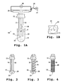
- an analyte-manipulation device configured to create a field gradient; e.g., at a tip region, such is shown at 12.
- the device 10 comprises a support 11 holding spaced-apart, co-extensive, elongate, electrically-conductive members, such as electrodes or wires 14, 16.
- Members 14, 16 can be held in any suitable fashion.
- members 14, 16 are held in a fashion permitting the members to move as a unit with support 11.
- members 14, 16 can be fixedly attached to support 11.
- members 14, 16 are firmly, yet removably, received within respective mounting holes formed through the support.
- An elongate narrow gap region 18 is defined between confronting side regions of members 14, 16.
- the dimension d of gap region 18 is within a range of from 20 ⁇ m and 1.50 mm. In a particular embodiment, the dimension d is between about 100 ⁇ m and 0.75 mm.
- Members 14, 16 are disposed for electrical communication, via circuitry 19, with an alternating current (AC) power supply 20 for providing a time-variant voltage difference therebetween.
- a concentration zone, indicated generally in the area denoted at 22, is located along a submerged portion of the gap region 18, between members 14, 16; and particularly near the tip region 12.
- the tip region 12 of the device 10 can be dipped into a sample containing one or more analytes of interest, such as the DNA-containing sample 23 held in tube or well 21 shown in Figure 1A .
- the analyte of interest is a polynucleotide such as DNA
- the DNA will be preferentially attracted to an increasing field gradient established in the gap region 18 between members 14 and 16; and particularly along the concentration zone 22.
- the gap region 18 is configured to hold a defined volume of liquid, e.g., in a fashion similar to that of a quill pen.
- the tip region 22 can then be moved to a receiving region (e.g., a clean, empty well of a microtitre plate) were the DNA can be deposited, e.g., upon discontinuing the AC field.
- a receiving region e.g., a clean, empty well of a microtitre plate
- the deposition of DNA into the receiving region can be expedited by applying a negative voltage to members 14, 16 to drive the DNA off the tip region (due to the repulsive effects of such negative voltage with respect to the negatively charged phosphate groups of the DNA).
- Figure 1A illustrates a DC power source 24 electrically connectable to (and disconnectable from) members 14, 16 by way of a switch 26 for such purpose.
- the receiving region e.g., a vessel, such as a tube or well
- the DNA will thereby be concentrated.
- the presently described device and method can assist in desalting the sample, since the tip region will not preferentially attract salts (as salts are not readily polarized).
- the combination of these two events can result in an increase in the amount of analyte available for injection into a separation channel during a DNA analysis.
- the device 10 can further include a detector (not shown) positioned such that material located in the concentration zone 22 may be detected.
- the device 10 can further optionally include a computer (not shown) connected to one or both of power supplies 20, 24, and/or to the detector (not shown), for example, to control and monitor the operation of the device and to manage the acquisition, analysis, and presentation of data.
- device 10 includes elongate members 14, 16 with tip regions (generally at 12) that are potted in a non-conductive material, such as a bead of resin 30, or other non-conducting material (e.g., an epoxy material, or the like).
- a non-conductive material such as a bead of resin 30, or other non-conducting material (e.g., an epoxy material, or the like). This can be useful, for example, to assist in maintaining a set (defmed) spacing between the opposed tip regions.
- a nonconductive filament is wrapped around one or more of the elongate members of the device.
- Figure 3 illustrates a non-conductive filament 34 wrapped in a spiral or helical fashion around member 16.
- Suitable filament materials include nylon, Teflon, polyimide or other plastics, among others.
- the filament can be held in place against member 16, for example, by tight wrapping and frictional forces, and/or through the use of one or more adhesives and/or fastening devices.
- the arrangement of Figure 3 can help to maintain a fixed spacing between members 14 and 16, as well as increase the amount of fluid the device will hold.
- the tip regions of members 14, 16 can be encapsulated with a porous material (e.g., sponge-like), as at 36, to assist in holding fluid and keeping the members 14, 16 spaced apart.
- a porous material e.g., sponge-like
- the wires need not be rod-like or cylindrical.
- a variety of geometries can be used to generate, tailor and even enhance (e.g., strengthen) the concentration of a field gradient.
- surface features such as points, sharp edges, corners, angles, bumps, protrusions, teeth, undulations, notches, indentations, waves, ripples, fins, or the like, can be provided along one or both of members 14, 16, e.g., in the vicinity of the tip regions.
- one or both elongated members are configured much in the fashion of a self-tapping screw.
- Such features can be advantageous, for example, to form and/or enhance the field gradient.
- sharp points or edges, indicated at 40 are formed along a majority of the length of each of members 14, 16 to each member's terminal end.
- an elongate non-conductive substrate is treated to provide conductive regions or paths therealong.
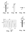
- an elongate non-conductive substrate 111 bears separated coatings on opposite sides, as indicated at 114 and 116.
- electrically conductive coatings are sprayed or deposited onto a suitable non-conductive substrate, such as a porous ceramic or polymeric substrate. Any suitable electrically conductive coating material can be used, e.g., metallic materials such as copper or aluminum, or electrically conductive resins or paints. In one embodiment a masking technique is employed to selectively deposit conductive materials.
- FIGS. 5D-5E show a support 111 and a plurality of analyte-manipulation devices 110 depending therefrom.
- Each of devices 110 is substantially as described above with respect to Figures 5A-5C .
- this multiple-device arrangement can be configured substantially in the fashion of a comb having an upper elongate, substantially horizontally disposed body portion 115 and spaced apart elongate members 117, analogous to the teeth of a comb, depending therefrom.
- Body 115 and members 117 can be integrally formed, or formed separately and attached to another one another by any suitable means (e.g., an adhesive or riveting).
- body 115 and members 117 are comprised of a non-conductive material bearing coatings of conductive material on opposite major surfaces thereof to form electrical paths therealong.
- the conductive coatings are disposed for electrical communication, via appropriate circuitry 19, with an AC power source 20.
- an analyte-manipulation device of the present invention is configured for manual operation.
- the support can be designed to be held in the hand of an operator, e.g., in a fashion similar to that of a manually-operable pipette, and readily moved from place to place (e.g., from a sample vessel to a receiving vessel).
- one or more analyte-manipulation devices are incorporated in an automated workstation, e.g., such as described in U.S. Patent No. 6,132,582 , entitled, "Sample handling system for a multi-channel capillary electrophoresis device” and/or in U.S. Patent No. 6,159,368 , entitled, "Multi-well Microfiltration Apparatus".
- the support can be adapted for automated positioning (e.g., x-y-z motion) permitting the device to address various regions or components of a workstation.
- the electrodes used to effect the alternating electric field can have a shape which serves to form an electric field that results in a defined concentration zone having desired dimensions.
- the spacing of the electrodes can be chosen so as to generate an electric field having sufficient strength to trap a polar analyte of interest, but not so high as to cause excessive bubble formation at the electrodes, e.g., see Washizu et al., IEEE Transactions on Industry Applications, 30 (4): 835-843 (1994 ).
- the spacing (see dimension d, in Figure 1 ) between the electrodes is between about 20 ⁇ m and 2 mm (e.g., about 0.75 - 1.0 mm).
- the alternating electric field used to trap a polarizable analyte can be any alternating electric field effective to manipulate, e.g., capture and concentrate, such an analyte.
- the alternating electric field of the invention may be characterized by a time vs. field strength profile, a frequency, and a maximum field strength.
- the properties of the alternating electric field required to manipulate the analyte will depend on a number of readily accessible experimental parameters including, for example, the magnitude of the dipole moment of a polar analyte, the dielectric constant of the supporting medium, and, in the case of an analyte having an induced dipole moment, the polarizability of the polar analyte or surrounding counter-ion microenvironment.
- the time vs. field strength profile of the alternating electric field may be sinusoidal, sawtooth, rectangular, superpositions of the foregoing, periodic or non-periodic, or any other profile capable of being generated using a suitable function generator, e.g., a Model 33120A 15 MHz Function / Arbitrary Waveform Generator from Agilent Technologies.
- a suitable function generator e.g., a Model 33120A 15 MHz Function / Arbitrary Waveform Generator from Agilent Technologies.
- the time vs. field strength profile of the alternating electric field is rectangular.
- the time vs. field strength profile of the alternating electric field is such that the time-averaged integrated field strength is zero where the average is taken over one complete cycle.
- the frequency of the alternating electric field may be any frequency capable of manipulating a portion of a polarizable analyte.
- the frequency of the alternating electric field may be between about 10 Hz and 100 megahertz (MHz).
- the frequency of the alternating electric field is between 1 kilohertz (KHz) and 100 KHz.
- the maximum field strength of the alternating electric field may be any field strength suitable to a particular application, in one embodiment, the maximum field strength of the alternating electric field, as measured by the peak field strength of the alternating electric field, is between about 100 V/cm and 20,000 V/cm; e.g., between 1,000 V/cm and 10,000 V/cm.
- the alternating electric field is spatially nonuniform.
- a trapped polar analyte is released from a concentration zone, for example, by reducing the trapping strength of the alternating electric field.
- the trapping strength of the alternating electric field may be modulated by changing the frequency, field strength, or both.
- another means for effecting release of an analyte involves establishment of a DC field having a polarity opposite to that of a trapped polarized analyte.
- a further analytical step can be performed subsequent to a sample or analyte concentration step according to the present invention.
- the analyte is directed into an analytical separation process, for example an electrophoretic or chromatographic separation process.
- concentration and localization methods carried out by the device of the present invention are particularly advantageous where the subsequent analytical separation process is electrophoresis because the pre-separation concentration step can provide a concentrated and narrow injection zone leading to both increased separation performance and enhanced detectability of the separated components.
- the nucleic acid analyte is subjected to a nucleic acid hybridization reaction in which the concentrated nucleic acid analyte is contacted with one or more complementary nucleic acids under conditions suitable for sequence-specific hybridization.
- the complementary nucleic acids are bound to a solid support, e.g., an array of support-bound nucleic acids including one or more potentially complementary nucleic acids.
- the support-bound nucleic acids may be synthetic polynucleotide probes, cDNA molecules, or any other nucleic acid or nucleic acid analog capable of sequence-specific hybridization. Exemplary arrays of support-bound nucleic acids are described elsewhere, e.g., Singh-Gasson et al., Nature Biotechnology, 17: 974-978 (1999 ); Blanchard and Friend, Nature Biotechnology, 17: 953 (1999 ); Brown et al., U.S. Patent No. 5,807,522 .
- the pre-hybridization concentration step of the present invention may result in an increased rate of hybridization, the ability to use a less concentrated sample, and/or an enhancement of the detectability of the products of the hybridization reaction.
- aqueous solution e.g., suspension
- force acts between two objects with charge, attractively between objects with opposite charges, repulsively between objects with similar charges. This property is exploited in certain embodiments of analyte-manipulation devices and methods of the present invention.
- concentration of charged analytes on a metallic electrode may be accompanied by the generation of bubbles.
- bubbles may hinder or interfere with the desired location of the analyte proximate or on the electrode.
- some embodiments of the present invention prefer the use of electrodes with a reduced or eliminated tendency for bubble formation as compared to, say, similarly dimensioned and disposed platinum electrodes under like conditions (referred to herein, collectively, as "bubble-free" electrodes).
- solid electrodes employable in the present invention include Pd, porous Pd, Ni(OH) 2 , Ni(OH) 4 , IrO 2 .
- ionic membranes such as Nafion
- gel-like electrode arrangements include capillary tubes or the like filed with gelatin, agarose, starch, or the like.
- electrically-conductive members of the device of the invention are formed or treated so as to exhibit desired wettability characteristics.
- selected regions of members 14, 16 can be provided with a surface that is hydrophilic, i.e., wettable.
- selected regions of the surfaces of members 14, 16 can be formed of a hydrophilic material and/or treated to exhibit hydrophilic characteristics.
- the surfaces have native, bound or covalently attached charged groups.
- selected regions of members 14, 16 can be provided with exterior surface regions that are hydrophobic, i. e., one that causes aqueous medium deposited on the surface to bead.
- selected regions of the exterior surfaces of members 14, 16 can be formed of a hydrophobic material and/or treated to exhibit hydrophobic characteristics.
- a variety of known hydrophobic polymers, such as polystyrene, polypropylene, and/or polyethylene, can be utilized to obtain the desired hydrophobic properties.
- a variety of lubricants or other conventional hydrophobic films can be applied to a member's exterior surface.
- upper regions of the members 14, 16 are treated so as to be hydrophobic and, optionally, lower regions of the members are treated so as to be hydrophilic.
- the sample holder can be adapted for movement.
Landscapes
- Health & Medical Sciences (AREA)
- Life Sciences & Earth Sciences (AREA)
- Chemical & Material Sciences (AREA)
- Analytical Chemistry (AREA)
- General Health & Medical Sciences (AREA)
- Molecular Biology (AREA)
- Biochemistry (AREA)
- Immunology (AREA)
- Physics & Mathematics (AREA)
- Chemical Kinetics & Catalysis (AREA)
- Pathology (AREA)
- General Physics & Mathematics (AREA)
- Electrochemistry (AREA)
- Hematology (AREA)
- Microelectronics & Electronic Packaging (AREA)
- Engineering & Computer Science (AREA)
- Clinical Laboratory Science (AREA)
- Apparatus Associated With Microorganisms And Enzymes (AREA)
- Physical Or Chemical Processes And Apparatus (AREA)
- Sampling And Sample Adjustment (AREA)
- Investigating Or Analysing Biological Materials (AREA)
- Investigating Or Analyzing Materials By The Use Of Electric Means (AREA)
- Medicines Containing Material From Animals Or Micro-Organisms (AREA)
Claims (13)
- Dispositif de manipulation de substance à analyser (10), comprenant :un support mobile (11) ;au moins deux éléments électriquement conducteurs, allongés, coextensifs (14, 16), lesdits éléments électriquement conducteurs (14, 16) étant maintenus par ledit support (11) pour un déplacement avec ce dernier, lesdits éléments électriquement conducteurs (14, 16) ayant des régions d'extrémité espacées (12), avec une région d'intervention (18) entre lesdites régions d'extrémité (12) définissant une zone de concentration (22) ;une source de courant alternatif (20) adaptée pour une communication électrique avec lesdits éléments électriquement conducteurs (14, 16) ;dans lequel, suite au positionnement dudit support (11) de sorte que lesdites régions d'extrémité (12) sont disposées dans une solution d'électrolyte contenant une substance à analyser (23) d'intérêt polarisable, ladite source de courant alternatif (20) peut fonctionner en combinaison avec lesdits éléments électriquement conducteurs (14, 16) pour établir un gradient de champ électrique entre lesdites régions d'extrémité (12) efficace pour piéger au moins une partie de ladite substance à analyser (23) polarisable dans la zone de concentration (22).
- Dispositif selon la revendication 1, comprenant en outre un matériau de résine (30), dans lequel au moins une partie de chacune desdites régions d'extrémité (12) desdits éléments électriquement conducteurs (14, 16) est contenue à l'intérieur dudit matériau de résine (30).
- Dispositif selon la revendication 2, dans lequel ledit matériau de résine (30) comprend une bille d'époxy.
- Dispositif selon la revendication 1, comprenant en outre un matériau poreux (36) encapsulant lesdites régions d'extrémité (12).
- Dispositif selon la revendication 1, dans lequel au moins une partie d'au moins l'un desdits éléments électriquement conducteurs (14, 16) comprend une ou plusieurs caractéristiques de surface choisies dans le groupe comprenant les bords, les coins, les angles, les bosses, les saillies, les dents, les ondulations, les encoches, les indentations, les ondes, les rides, les ailettes, et l'une quelconque de leur combinaison.
- Dispositif selon la revendication 5, dans lequel lesdits éléments (14, 16) comprennent des caractéristiques de surface le long des parties en vis-à-vis de leurs régions d'extrémité (12) comprenant des bords ou des pointes (40).
- Dispositif selon la revendication 1, comprenant en outre un filament non conducteur (34) s'étendant le long d'au moins l'un desdits éléments (14, 16).
- Dispositif selon la revendication 1, dans lequel ledit support (11) est configuré comme une poignée permettant à un opérateur de maintenir et de positionner le dispositif à la main.
- Dispositif selon la revendication 11, dans lequel deux paires ou plus desdits éléments électriquement conducteurs allongés coextensifs (14, 16) sont maintenues par ledit support (11).
- Dispositif selon la revendication 1, comprenant en outre une source de courant continu (24) adaptée pour la communication électrique avec lesdits éléments électriquement conducteurs (14, 16).
- Dispositif selon la revendication 1, comprenant en outre un support d'échantillon (21), dans lequel lesdits éléments (14, 16) et ledit support d'échantillon (21) sont adaptés pour le mouvement relatif entre une première position dans laquelle au moins une partie desdits éléments (14, 16) est disposée à l'intérieur dudit support d'échantillon (21) et une seconde position dans laquelle lesdits éléments (14, 16) sont disposés à l'extérieur dudit support d'échantillon (21).
- Dispositif selon la revendication 11, comprenant en outre une unité de commande pour commander la position des éléments électriquement conducteurs (14, 16) par rapport audit support d'échantillon (21).
- Dispositif selon la revendication 11, comprenant en outre un appareil de manipulation de support pour déplacer ledit support d'échantillon (21) vers et à distance desdits éléments électriquement conducteurs (14, 16).
Priority Applications (3)
| Application Number | Priority Date | Filing Date | Title |
|---|---|---|---|
| EP10013119A EP2295956A3 (fr) | 2001-08-24 | 2002-08-23 | Manipulation de composés à analyser à l'aide de champs électriques |
| EP10000182A EP2187200A3 (fr) | 2001-08-24 | 2002-08-23 | Manipulation de composés à analyser à l'aide de champs électriques |
| EP06003605A EP1674159A1 (fr) | 2001-08-24 | 2002-08-23 | Manipulation de composés à analyser à l'aide de champs électriques |
Applications Claiming Priority (3)
| Application Number | Priority Date | Filing Date | Title |
|---|---|---|---|
| US09/938,894 US7014744B2 (en) | 2001-08-24 | 2001-08-24 | Method of purification and concentration using AC fields with a transfer tip |
| US938894 | 2001-08-24 | ||
| PCT/US2002/026827 WO2003019164A1 (fr) | 2001-08-24 | 2002-08-23 | Manipulation de substances a analyser au moyen de champs electriques |
Related Child Applications (3)
| Application Number | Title | Priority Date | Filing Date |
|---|---|---|---|
| EP06003605A Division EP1674159A1 (fr) | 2001-08-24 | 2002-08-23 | Manipulation de composés à analyser à l'aide de champs électriques |
| EP06003605.0 Division-Into | 2006-02-22 | ||
| EP10000182.5 Division-Into | 2010-01-11 |
Publications (3)
| Publication Number | Publication Date |
|---|---|
| EP1419376A1 EP1419376A1 (fr) | 2004-05-19 |
| EP1419376A4 EP1419376A4 (fr) | 2005-06-01 |
| EP1419376B1 true EP1419376B1 (fr) | 2010-10-06 |
Family
ID=25472154
Family Applications (4)
| Application Number | Title | Priority Date | Filing Date |
|---|---|---|---|
| EP10000182A Withdrawn EP2187200A3 (fr) | 2001-08-24 | 2002-08-23 | Manipulation de composés à analyser à l'aide de champs électriques |
| EP06003605A Withdrawn EP1674159A1 (fr) | 2001-08-24 | 2002-08-23 | Manipulation de composés à analyser à l'aide de champs électriques |
| EP10013119A Withdrawn EP2295956A3 (fr) | 2001-08-24 | 2002-08-23 | Manipulation de composés à analyser à l'aide de champs électriques |
| EP02766066A Expired - Lifetime EP1419376B1 (fr) | 2001-08-24 | 2002-08-23 | Manipulation de substances a analyser au moyen de champs electriques |
Family Applications Before (3)
| Application Number | Title | Priority Date | Filing Date |
|---|---|---|---|
| EP10000182A Withdrawn EP2187200A3 (fr) | 2001-08-24 | 2002-08-23 | Manipulation de composés à analyser à l'aide de champs électriques |
| EP06003605A Withdrawn EP1674159A1 (fr) | 2001-08-24 | 2002-08-23 | Manipulation de composés à analyser à l'aide de champs électriques |
| EP10013119A Withdrawn EP2295956A3 (fr) | 2001-08-24 | 2002-08-23 | Manipulation de composés à analyser à l'aide de champs électriques |
Country Status (7)
| Country | Link |
|---|---|
| US (3) | US7014744B2 (fr) |
| EP (4) | EP2187200A3 (fr) |
| JP (2) | JP2005501251A (fr) |
| AT (1) | ATE483967T1 (fr) |
| CA (1) | CA2456684A1 (fr) |
| DE (1) | DE60237900D1 (fr) |
| WO (1) | WO2003019164A1 (fr) |
Families Citing this family (24)
| Publication number | Priority date | Publication date | Assignee | Title |
|---|---|---|---|---|
| US7014744B2 (en) * | 2001-08-24 | 2006-03-21 | Applera Corporation | Method of purification and concentration using AC fields with a transfer tip |
| US7188731B2 (en) | 2002-08-26 | 2007-03-13 | The Regents Of The University Of California | Variable flexure-based fluid filter |
| US7147764B2 (en) | 2003-03-28 | 2006-12-12 | Applera Corporation | Dual electrode injection of analyte into a capillary electrophoretic device |
| WO2006087890A1 (fr) * | 2005-02-15 | 2006-08-24 | Kochi University Of Technology | Dispositif de manipulation sans contact avec une paire d’électrodes et procédé de manipulation |
| KR100773542B1 (ko) | 2005-07-19 | 2007-11-07 | 삼성전자주식회사 | 유체의 pH를 전기화학적으로 조절하기 위한 미세유동장치및 그를 이용하여 pH를 조절하는 방법 |
| US8734003B2 (en) * | 2005-09-15 | 2014-05-27 | Alcatel Lucent | Micro-chemical mixing |
| US8721161B2 (en) * | 2005-09-15 | 2014-05-13 | Alcatel Lucent | Fluid oscillations on structured surfaces |
| US20070059213A1 (en) * | 2005-09-15 | 2007-03-15 | Lucent Technologies Inc. | Heat-induced transitions on a structured surface |
| IL203741A (en) | 2010-02-04 | 2016-07-31 | Ben Gurion Univ Of The Negev Res And Dev Authority | Neutralizing harmful powders by mail |
| US9618431B2 (en) * | 2010-11-30 | 2017-04-11 | Inspirotec, Inc. | Electrokinetic device for capturing assayable agents in a dielectric fluid |
| US9308542B2 (en) * | 2011-07-29 | 2016-04-12 | Tokyo Electron Limited | Treatment solution supply apparatus, treatment solution supply method, and computer storage medium |
| US9852560B2 (en) | 2013-03-08 | 2017-12-26 | Lear Corporation | Vehicle remote function system and method for effectuating vehicle operations based on vehicle FOB movement |
| JP2017512483A (ja) * | 2014-04-08 | 2017-05-25 | バイオロジカル ダイナミクス,インク. | 生体物質の単離のための改良された装置 |
| KR20170106399A (ko) * | 2015-01-14 | 2017-09-20 | 프랭크 토마스 하틀리 | 체액 추출 장치 및 방법 |
| CN107636445A (zh) | 2015-03-09 | 2018-01-26 | 加州理工学院 | 中红外高光谱的光谱系统及其方法 |
| EP3112869A1 (fr) * | 2015-06-30 | 2017-01-04 | IMEC vzw | Dispositif de capteur |
| JP6714924B2 (ja) * | 2015-11-30 | 2020-07-01 | 国立大学法人大阪大学 | サンプル検出用デバイス、サンプル検出装置及びイオン電流の検出方法 |
| US10545073B2 (en) * | 2016-03-02 | 2020-01-28 | Jp Scientific Limited | Method and instrument for extracting a component from a sample |
| CN115487880A (zh) | 2016-03-24 | 2022-12-20 | 生物动力学公司 | 一次性射流卡盘及组件 |
| US11731132B2 (en) | 2017-12-19 | 2023-08-22 | Biological Dynamics, Inc. | Methods and devices for detection of multiple analytes from a biological sample |
| WO2019195196A1 (fr) | 2018-04-02 | 2019-10-10 | Biological Dynamics, Inc. | Matériaux diélectriques |
| WO2020079220A1 (fr) * | 2018-10-18 | 2020-04-23 | Danmarks Tekniske Universitet | Procédés d'extraction de molécules |
| WO2020163492A1 (fr) | 2019-02-06 | 2020-08-13 | California Institute Of Technology | Spectromètre hyperspectral compact dans l'infrarouge moyen |
| US11313722B2 (en) | 2019-11-08 | 2022-04-26 | California Institute Of Technology | Infrared spectrometer having dielectric-polymer-based spectral filter |
Family Cites Families (46)
| Publication number | Priority date | Publication date | Assignee | Title |
|---|---|---|---|---|
| US3277257A (en) * | 1963-08-28 | 1966-10-04 | Doktor Benjamin | Column-spring type snap-action electrical switch |
| US4124470A (en) * | 1974-04-30 | 1978-11-07 | Harald Dahms | Method and apparatus for electrophoresis |
| US4326934A (en) * | 1979-12-31 | 1982-04-27 | Pohl Herbert A | Continuous dielectrophoretic cell classification method |
| DE3317415A1 (de) * | 1983-05-13 | 1984-11-15 | Kernforschungsanlage Jülich GmbH, 5170 Jülich | Kammer zur behandlung von zellen im elektrischen feld |
| US4661451A (en) * | 1984-02-06 | 1987-04-28 | Ortho Diagnostic Systems, Inc. | Methods for immobilizing and translocating biological cells |
| US4643814A (en) * | 1985-02-20 | 1987-02-17 | Ionics, Incorporated | Structure selective fibrous sorbents and method and apparatus for using the same |
| DE3522610A1 (de) * | 1985-06-12 | 1986-12-18 | Kernforschungsanlage Jülich GmbH, 5170 Jülich | Kammer fuer die behandlung von zellen im elektrischen feld |
| JPS61285984A (ja) * | 1985-06-12 | 1986-12-16 | フォルシュングスツエントルム・ユーリッヒ・ゲゼルシャフト・ミト・ベシュレンクテル・ハフツング | 電気的な場において細胞を処理するための装置 |
| US4911806A (en) * | 1987-02-27 | 1990-03-27 | Biotronics | Method and apparatus for separating particles in liquid suspension utilizing oscillating electric and magnetic fields |
| US4767514A (en) * | 1987-03-31 | 1988-08-30 | Candor James T | Apparatus and method for removing liquid from liquid bearing material |
| US4822470A (en) * | 1987-10-09 | 1989-04-18 | Baylor College Of Medicine | Method of and apparatus for cell poration and cell fusion using radiofrequency electrical pulses |
| US4970154A (en) * | 1987-10-09 | 1990-11-13 | Baylor College Of Medicine | Method for inserting foreign genes into cells using pulsed radiofrequency |
| USRE35102E (en) | 1989-06-01 | 1995-11-28 | The Board Of Trustees Of The Leland Stanford Junior University | Capillary electrophoretic device employing structure permitting electrical contact through ionic movement |
| US5164055A (en) * | 1990-01-29 | 1992-11-17 | Applied Biosystems, Inc. | High-viscosity polymer matrix and methods |
| AU8285691A (en) | 1990-11-16 | 1992-06-11 | Steven Kaali | Alternating current supplied electrically conductive method and system for treatment of blood and/or other body fluids and/or synthetic fluids with electric forces |
| JP2937498B2 (ja) * | 1991-01-28 | 1999-08-23 | 科学技術振興事業団 | 生体関連物質の捕捉装置とそれを用いた生体関連物質の観察方法 |
| US6051380A (en) * | 1993-11-01 | 2000-04-18 | Nanogen, Inc. | Methods and procedures for molecular biological analysis and diagnostics |
| GB9208357D0 (en) * | 1992-04-16 | 1992-06-03 | British Tech Group | Apparatus for separating a mixture |
| US5427663A (en) * | 1993-06-08 | 1995-06-27 | British Technology Group Usa Inc. | Microlithographic array for macromolecule and cell fractionation |
| US5422272A (en) * | 1993-07-14 | 1995-06-06 | Andrew A. Papp | Improvements to apparatus and method for electroporation |
| US5423966A (en) * | 1994-01-25 | 1995-06-13 | Perkin-Elmer Corporation | On line ion contaminant removal apparatus and method for capillary electrophoresis |
| US5807522A (en) | 1994-06-17 | 1998-09-15 | The Board Of Trustees Of The Leland Stanford Junior University | Methods for fabricating microarrays of biological samples |
| US5985119A (en) * | 1994-11-10 | 1999-11-16 | Sarnoff Corporation | Electrokinetic pumping |
| EP0846161B1 (fr) | 1995-08-25 | 2005-08-17 | Affymetrix, Inc. (a Delaware Corporation) | Liberation de matiere intracellulaire |
| JP3547899B2 (ja) * | 1996-04-05 | 2004-07-28 | 株式会社モリテックス | マイクロマニピュレータ及びこれに用いるセル |
| GB9608644D0 (en) | 1996-04-26 | 1996-07-03 | Scient Genarics Ltd | Nucleic acid manipulation |
| US5800690A (en) * | 1996-07-03 | 1998-09-01 | Caliper Technologies Corporation | Variable control of electroosmotic and/or electrophoretic forces within a fluid-containing structure via electrical forces |
| US6277257B1 (en) | 1997-06-25 | 2001-08-21 | Sandia Corporation | Electrokinetic high pressure hydraulic system |
| US5989402A (en) * | 1997-08-29 | 1999-11-23 | Caliper Technologies Corp. | Controller/detector interfaces for microfluidic systems |
| DE19757112C2 (de) * | 1997-09-15 | 2001-01-11 | Heraeus Electro Nite Int | Gassensor |
| US6306590B1 (en) * | 1998-06-08 | 2001-10-23 | Caliper Technologies Corp. | Microfluidic matrix localization apparatus and methods |
| US6132582A (en) | 1998-09-14 | 2000-10-17 | The Perkin-Elmer Corporation | Sample handling system for a multi-channel capillary electrophoresis device |
| US6149787A (en) * | 1998-10-14 | 2000-11-21 | Caliper Technologies Corp. | External material accession systems and methods |
| US6159368A (en) | 1998-10-29 | 2000-12-12 | The Perkin-Elmer Corporation | Multi-well microfiltration apparatus |
| US6203683B1 (en) * | 1998-11-09 | 2001-03-20 | Princeton University | Electrodynamically focused thermal cycling device |
| JP2002537767A (ja) * | 1999-02-15 | 2002-11-12 | フラウンホファー ゲセルシャフトツール フェールデルンク ダー アンゲヴァンテン フォルシュンク エー.ファオ. | 物質をinsituで分割し濃縮するための方法およびプローブ担体系 |
| HUP9900603A1 (hu) * | 1999-03-12 | 2000-12-28 | MTA Mezőgazdasági Kutatóintézete | Eljárás és berendezés magasabbrendű növények polarizálható sejtjeinek immobilizálására nagy frekvenciájú váltóáram alkalmazásával |
| US6306273B1 (en) * | 1999-04-13 | 2001-10-23 | Aclara Biosciences, Inc. | Methods and compositions for conducting processes in microfluidic devices |
| US6375817B1 (en) * | 1999-04-16 | 2002-04-23 | Perseptive Biosystems, Inc. | Apparatus and methods for sample analysis |
| DE19931807C1 (de) * | 1999-07-08 | 2000-09-07 | Draeger Medizintech Gmbh | Beatmungsvorrichtung mit einem Überdruckventil |
| GB9917469D0 (en) | 1999-07-27 | 1999-09-29 | Baker Matthew J | Extraction of nucleic acids |
| JP2001165905A (ja) * | 1999-09-30 | 2001-06-22 | Wako Pure Chem Ind Ltd | 誘電泳動力を用いた物質の分離方法 |
| MXPA02008290A (es) * | 2000-02-23 | 2004-09-10 | Caliper Technologies Inc | Sistema de control de presion de multi-reserva-. |
| US6537433B1 (en) * | 2000-03-10 | 2003-03-25 | Applera Corporation | Methods and apparatus for the location and concentration of polar analytes using an alternating electric field |
| US6890409B2 (en) * | 2001-08-24 | 2005-05-10 | Applera Corporation | Bubble-free and pressure-generating electrodes for electrophoretic and electroosmotic devices |
| US7014744B2 (en) * | 2001-08-24 | 2006-03-21 | Applera Corporation | Method of purification and concentration using AC fields with a transfer tip |
-
2001
- 2001-08-24 US US09/938,894 patent/US7014744B2/en not_active Expired - Lifetime
-
2002
- 2002-08-23 EP EP10000182A patent/EP2187200A3/fr not_active Withdrawn
- 2002-08-23 EP EP06003605A patent/EP1674159A1/fr not_active Withdrawn
- 2002-08-23 AT AT02766066T patent/ATE483967T1/de not_active IP Right Cessation
- 2002-08-23 CA CA002456684A patent/CA2456684A1/fr not_active Abandoned
- 2002-08-23 DE DE60237900T patent/DE60237900D1/de not_active Expired - Lifetime
- 2002-08-23 JP JP2003523982A patent/JP2005501251A/ja active Pending
- 2002-08-23 EP EP10013119A patent/EP2295956A3/fr not_active Withdrawn
- 2002-08-23 EP EP02766066A patent/EP1419376B1/fr not_active Expired - Lifetime
- 2002-08-23 WO PCT/US2002/026827 patent/WO2003019164A1/fr not_active Ceased
-
2006
- 2006-01-24 US US11/338,255 patent/US7611614B2/en not_active Expired - Lifetime
-
2007
- 2007-02-14 JP JP2007034138A patent/JP2007178437A/ja active Pending
-
2009
- 2009-10-15 US US12/580,220 patent/US20100032298A1/en not_active Abandoned
Also Published As
| Publication number | Publication date |
|---|---|
| CA2456684A1 (fr) | 2003-03-06 |
| WO2003019164A1 (fr) | 2003-03-06 |
| EP1419376A1 (fr) | 2004-05-19 |
| EP2295956A2 (fr) | 2011-03-16 |
| US7611614B2 (en) | 2009-11-03 |
| DE60237900D1 (de) | 2010-11-18 |
| JP2007178437A (ja) | 2007-07-12 |
| US20100032298A1 (en) | 2010-02-11 |
| EP2187200A3 (fr) | 2010-07-14 |
| EP2295956A3 (fr) | 2011-09-14 |
| ATE483967T1 (de) | 2010-10-15 |
| EP1419376A4 (fr) | 2005-06-01 |
| US7014744B2 (en) | 2006-03-21 |
| JP2005501251A (ja) | 2005-01-13 |
| US20030038032A1 (en) | 2003-02-27 |
| US20060124463A1 (en) | 2006-06-15 |
| EP2187200A2 (fr) | 2010-05-19 |
| EP1674159A1 (fr) | 2006-06-28 |
Similar Documents
| Publication | Publication Date | Title |
|---|---|---|
| US20100032298A1 (en) | Method of Cell Capture | |
| US7704363B2 (en) | Methods and apparatus for the location and concentration of polar analytes using an alternating electric field | |
| US5202010A (en) | Automated capillary electrophoresis apparatus | |
| US7641779B2 (en) | Method and apparatus for programmable fluidic processing | |
| US8133371B2 (en) | Scodaphoresis and methods and apparatus for moving and concentrating particles | |
| US20090058428A1 (en) | Method and device for monitoring and controlling fluid locomotion | |
| JP2006300946A (ja) | マイクロ流体の方法および質量を二種の不混和性相間で移送する装置 | |
| EP1139087A2 (fr) | Dispositif et procédé pour l'extraction en phase solide | |
| US20080296157A1 (en) | Method and Device for Handling Sedimenting Particles | |
| AU2002329815A1 (en) | Manipulation of analytes using electric fields | |
| Ichiki et al. | Microchip technologies for the analysis of biological cells | |
| US20230132614A1 (en) | Electromagnetic assemblies for processing fluids | |
| US20100018861A1 (en) | Electromotive liquid handling method and apparatus | |
| WO2004039499A2 (fr) | Procede de chargement et dechargement de macromolecules sur et hors de dispositifs microfluidiques |
Legal Events
| Date | Code | Title | Description |
|---|---|---|---|
| PUAI | Public reference made under article 153(3) epc to a published international application that has entered the european phase |
Free format text: ORIGINAL CODE: 0009012 |
|
| 17P | Request for examination filed |
Effective date: 20040217 |
|
| AK | Designated contracting states |
Kind code of ref document: A1 Designated state(s): AT BE BG CH CY CZ DE DK EE ES FI FR GB GR IE IT LI LU MC NL PT SE SK TR |
|
| AX | Request for extension of the european patent |
Extension state: AL LT LV MK RO SI |
|
| RIC1 | Information provided on ipc code assigned before grant |
Ipc: 7B 03C 5/02 B Ipc: 7B 01L 3/00 B Ipc: 7G 01N 27/00 A |
|
| A4 | Supplementary search report drawn up and despatched |
Effective date: 20050413 |
|
| GRAP | Despatch of communication of intention to grant a patent |
Free format text: ORIGINAL CODE: EPIDOSNIGR1 |
|
| RAP1 | Party data changed (applicant data changed or rights of an application transferred) |
Owner name: LIFE TECHNOLOGIES CORPORATION |
|
| RAP1 | Party data changed (applicant data changed or rights of an application transferred) |
Owner name: LIFE TECHNOLOGIES CORPORATION |
|
| GRAS | Grant fee paid |
Free format text: ORIGINAL CODE: EPIDOSNIGR3 |
|
| GRAA | (expected) grant |
Free format text: ORIGINAL CODE: 0009210 |
|
| AK | Designated contracting states |
Kind code of ref document: B1 Designated state(s): AT BE BG CH CY CZ DE DK EE ES FI FR GB GR IE IT LI LU MC NL PT SE SK TR |
|
| REG | Reference to a national code |
Ref country code: GB Ref legal event code: FG4D |
|
| REG | Reference to a national code |
Ref country code: CH Ref legal event code: EP |
|
| REG | Reference to a national code |
Ref country code: IE Ref legal event code: FG4D |
|
| REF | Corresponds to: |
Ref document number: 60237900 Country of ref document: DE Date of ref document: 20101118 Kind code of ref document: P |
|
| REG | Reference to a national code |
Ref country code: NL Ref legal event code: VDEP Effective date: 20101006 |
|
| PG25 | Lapsed in a contracting state [announced via postgrant information from national office to epo] |
Ref country code: AT Free format text: LAPSE BECAUSE OF FAILURE TO SUBMIT A TRANSLATION OF THE DESCRIPTION OR TO PAY THE FEE WITHIN THE PRESCRIBED TIME-LIMIT Effective date: 20101006 Ref country code: PT Free format text: LAPSE BECAUSE OF FAILURE TO SUBMIT A TRANSLATION OF THE DESCRIPTION OR TO PAY THE FEE WITHIN THE PRESCRIBED TIME-LIMIT Effective date: 20110207 Ref country code: FI Free format text: LAPSE BECAUSE OF FAILURE TO SUBMIT A TRANSLATION OF THE DESCRIPTION OR TO PAY THE FEE WITHIN THE PRESCRIBED TIME-LIMIT Effective date: 20101006 Ref country code: SE Free format text: LAPSE BECAUSE OF FAILURE TO SUBMIT A TRANSLATION OF THE DESCRIPTION OR TO PAY THE FEE WITHIN THE PRESCRIBED TIME-LIMIT Effective date: 20101006 Ref country code: BG Free format text: LAPSE BECAUSE OF FAILURE TO SUBMIT A TRANSLATION OF THE DESCRIPTION OR TO PAY THE FEE WITHIN THE PRESCRIBED TIME-LIMIT Effective date: 20110106 Ref country code: NL Free format text: LAPSE BECAUSE OF FAILURE TO SUBMIT A TRANSLATION OF THE DESCRIPTION OR TO PAY THE FEE WITHIN THE PRESCRIBED TIME-LIMIT Effective date: 20101006 |
|
| PG25 | Lapsed in a contracting state [announced via postgrant information from national office to epo] |
Ref country code: BE Free format text: LAPSE BECAUSE OF FAILURE TO SUBMIT A TRANSLATION OF THE DESCRIPTION OR TO PAY THE FEE WITHIN THE PRESCRIBED TIME-LIMIT Effective date: 20101006 Ref country code: GR Free format text: LAPSE BECAUSE OF FAILURE TO SUBMIT A TRANSLATION OF THE DESCRIPTION OR TO PAY THE FEE WITHIN THE PRESCRIBED TIME-LIMIT Effective date: 20110107 |
|
| PG25 | Lapsed in a contracting state [announced via postgrant information from national office to epo] |
Ref country code: CZ Free format text: LAPSE BECAUSE OF FAILURE TO SUBMIT A TRANSLATION OF THE DESCRIPTION OR TO PAY THE FEE WITHIN THE PRESCRIBED TIME-LIMIT Effective date: 20101006 Ref country code: EE Free format text: LAPSE BECAUSE OF FAILURE TO SUBMIT A TRANSLATION OF THE DESCRIPTION OR TO PAY THE FEE WITHIN THE PRESCRIBED TIME-LIMIT Effective date: 20101006 Ref country code: ES Free format text: LAPSE BECAUSE OF FAILURE TO SUBMIT A TRANSLATION OF THE DESCRIPTION OR TO PAY THE FEE WITHIN THE PRESCRIBED TIME-LIMIT Effective date: 20110117 |
|
| PLBE | No opposition filed within time limit |
Free format text: ORIGINAL CODE: 0009261 |
|
| STAA | Information on the status of an ep patent application or granted ep patent |
Free format text: STATUS: NO OPPOSITION FILED WITHIN TIME LIMIT |
|
| PG25 | Lapsed in a contracting state [announced via postgrant information from national office to epo] |
Ref country code: DK Free format text: LAPSE BECAUSE OF FAILURE TO SUBMIT A TRANSLATION OF THE DESCRIPTION OR TO PAY THE FEE WITHIN THE PRESCRIBED TIME-LIMIT Effective date: 20101006 Ref country code: SK Free format text: LAPSE BECAUSE OF FAILURE TO SUBMIT A TRANSLATION OF THE DESCRIPTION OR TO PAY THE FEE WITHIN THE PRESCRIBED TIME-LIMIT Effective date: 20101006 |
|
| 26N | No opposition filed |
Effective date: 20110707 |
|
| REG | Reference to a national code |
Ref country code: DE Ref legal event code: R097 Ref document number: 60237900 Country of ref document: DE Effective date: 20110707 |
|
| PG25 | Lapsed in a contracting state [announced via postgrant information from national office to epo] |
Ref country code: IT Free format text: LAPSE BECAUSE OF FAILURE TO SUBMIT A TRANSLATION OF THE DESCRIPTION OR TO PAY THE FEE WITHIN THE PRESCRIBED TIME-LIMIT Effective date: 20101006 |
|
| PG25 | Lapsed in a contracting state [announced via postgrant information from national office to epo] |
Ref country code: MC Free format text: LAPSE BECAUSE OF NON-PAYMENT OF DUE FEES Effective date: 20110831 |
|
| REG | Reference to a national code |
Ref country code: CH Ref legal event code: PL |
|
| GBPC | Gb: european patent ceased through non-payment of renewal fee |
Effective date: 20110823 |
|
| PG25 | Lapsed in a contracting state [announced via postgrant information from national office to epo] |
Ref country code: CH Free format text: LAPSE BECAUSE OF NON-PAYMENT OF DUE FEES Effective date: 20110831 Ref country code: LI Free format text: LAPSE BECAUSE OF NON-PAYMENT OF DUE FEES Effective date: 20110831 |
|
| REG | Reference to a national code |
Ref country code: FR Ref legal event code: ST Effective date: 20120430 |
|
| REG | Reference to a national code |
Ref country code: IE Ref legal event code: MM4A |
|
| REG | Reference to a national code |
Ref country code: DE Ref legal event code: R119 Ref document number: 60237900 Country of ref document: DE Effective date: 20120301 |
|
| PG25 | Lapsed in a contracting state [announced via postgrant information from national office to epo] |
Ref country code: IE Free format text: LAPSE BECAUSE OF NON-PAYMENT OF DUE FEES Effective date: 20110823 |
|
| PG25 | Lapsed in a contracting state [announced via postgrant information from national office to epo] |
Ref country code: GB Free format text: LAPSE BECAUSE OF NON-PAYMENT OF DUE FEES Effective date: 20110823 Ref country code: FR Free format text: LAPSE BECAUSE OF NON-PAYMENT OF DUE FEES Effective date: 20110831 |
|
| PG25 | Lapsed in a contracting state [announced via postgrant information from national office to epo] |
Ref country code: CY Free format text: LAPSE BECAUSE OF EXPIRATION OF PROTECTION Effective date: 20101006 Ref country code: LU Free format text: LAPSE BECAUSE OF NON-PAYMENT OF DUE FEES Effective date: 20110823 |
|
| PG25 | Lapsed in a contracting state [announced via postgrant information from national office to epo] |
Ref country code: DE Free format text: LAPSE BECAUSE OF NON-PAYMENT OF DUE FEES Effective date: 20120301 |
|
| PG25 | Lapsed in a contracting state [announced via postgrant information from national office to epo] |
Ref country code: TR Free format text: LAPSE BECAUSE OF FAILURE TO SUBMIT A TRANSLATION OF THE DESCRIPTION OR TO PAY THE FEE WITHIN THE PRESCRIBED TIME-LIMIT Effective date: 20101006 |