EP1419397B1 - Gasgefüllter alphazähler mit ultraniedrigem hintergrund - Google Patents
Gasgefüllter alphazähler mit ultraniedrigem hintergrund Download PDFInfo
- Publication number
- EP1419397B1 EP1419397B1 EP02757333.6A EP02757333A EP1419397B1 EP 1419397 B1 EP1419397 B1 EP 1419397B1 EP 02757333 A EP02757333 A EP 02757333A EP 1419397 B1 EP1419397 B1 EP 1419397B1
- Authority
- EP
- European Patent Office
- Prior art keywords
- pulse
- anode
- counter
- chamber
- output signal
- Prior art date
- Legal status (The legal status is an assumption and is not a legal conclusion. Google has not performed a legal analysis and makes no representation as to the accuracy of the status listed.)
- Expired - Lifetime
Links
- 239000002245 particle Substances 0.000 claims description 83
- 238000000034 method Methods 0.000 claims description 49
- 239000007789 gas Substances 0.000 claims description 44
- 239000000463 material Substances 0.000 claims description 22
- 238000007493 shaping process Methods 0.000 claims description 16
- 238000005259 measurement Methods 0.000 claims description 15
- 238000012545 processing Methods 0.000 claims description 15
- 230000005684 electric field Effects 0.000 claims description 12
- 238000004458 analytical method Methods 0.000 claims description 8
- 238000010276 construction Methods 0.000 claims description 6
- 238000012935 Averaging Methods 0.000 claims description 5
- IJGRMHOSHXDMSA-UHFFFAOYSA-N nitrogen Substances N#N IJGRMHOSHXDMSA-UHFFFAOYSA-N 0.000 claims description 5
- 229910052757 nitrogen Inorganic materials 0.000 claims description 3
- 229910052704 radon Inorganic materials 0.000 claims description 3
- SYUHGPGVQRZVTB-UHFFFAOYSA-N radon atom Chemical compound [Rn] SYUHGPGVQRZVTB-UHFFFAOYSA-N 0.000 claims description 3
- 230000004069 differentiation Effects 0.000 claims description 2
- 239000000523 sample Substances 0.000 claims 20
- 238000013508 migration Methods 0.000 claims 2
- 230000005012 migration Effects 0.000 claims 2
- 239000002131 composite material Substances 0.000 claims 1
- 230000001143 conditioned effect Effects 0.000 claims 1
- 230000008878 coupling Effects 0.000 claims 1
- 238000010168 coupling process Methods 0.000 claims 1
- 238000005859 coupling reaction Methods 0.000 claims 1
- 239000012212 insulator Substances 0.000 claims 1
- QJGQUHMNIGDVPM-UHFFFAOYSA-N nitrogen group Chemical group [N] QJGQUHMNIGDVPM-UHFFFAOYSA-N 0.000 claims 1
- 238000012360 testing method Methods 0.000 description 24
- 238000013461 design Methods 0.000 description 22
- 230000008901 benefit Effects 0.000 description 6
- XUIMIQQOPSSXEZ-UHFFFAOYSA-N Silicon Chemical compound [Si] XUIMIQQOPSSXEZ-UHFFFAOYSA-N 0.000 description 5
- 238000007792 addition Methods 0.000 description 5
- 238000010586 diagram Methods 0.000 description 5
- 230000000694 effects Effects 0.000 description 5
- 230000001965 increasing effect Effects 0.000 description 5
- 150000002500 ions Chemical class 0.000 description 5
- 238000010926 purge Methods 0.000 description 5
- 230000009467 reduction Effects 0.000 description 5
- 239000003990 capacitor Substances 0.000 description 4
- 230000007613 environmental effect Effects 0.000 description 4
- 230000005855 radiation Effects 0.000 description 4
- 229910052710 silicon Inorganic materials 0.000 description 4
- 239000010703 silicon Substances 0.000 description 4
- FQZYTYWMLGAPFJ-OQKDUQJOSA-N tamoxifen citrate Chemical compound [H+].[H+].[H+].[O-]C(=O)CC(O)(CC([O-])=O)C([O-])=O.C=1C=CC=CC=1C(/CC)=C(C=1C=CC(OCCN(C)C)=CC=1)/C1=CC=CC=C1 FQZYTYWMLGAPFJ-OQKDUQJOSA-N 0.000 description 4
- 238000013459 approach Methods 0.000 description 3
- JJWKPURADFRFRB-UHFFFAOYSA-N carbonyl sulfide Chemical compound O=C=S JJWKPURADFRFRB-UHFFFAOYSA-N 0.000 description 3
- 238000011109 contamination Methods 0.000 description 3
- 230000003111 delayed effect Effects 0.000 description 3
- 238000005516 engineering process Methods 0.000 description 3
- 230000006872 improvement Effects 0.000 description 3
- 238000012986 modification Methods 0.000 description 3
- 230000004048 modification Effects 0.000 description 3
- 239000004033 plastic Substances 0.000 description 3
- 229920003023 plastic Polymers 0.000 description 3
- 239000004065 semiconductor Substances 0.000 description 3
- 230000035945 sensitivity Effects 0.000 description 3
- 239000004020 conductor Substances 0.000 description 2
- 239000004035 construction material Substances 0.000 description 2
- 230000001934 delay Effects 0.000 description 2
- 230000008569 process Effects 0.000 description 2
- 238000000926 separation method Methods 0.000 description 2
- 238000001228 spectrum Methods 0.000 description 2
- 230000001629 suppression Effects 0.000 description 2
- XLYOFNOQVPJJNP-UHFFFAOYSA-N water Chemical compound O XLYOFNOQVPJJNP-UHFFFAOYSA-N 0.000 description 2
- RYGMFSIKBFXOCR-UHFFFAOYSA-N Copper Chemical compound [Cu] RYGMFSIKBFXOCR-UHFFFAOYSA-N 0.000 description 1
- 229920005479 Lucite® Polymers 0.000 description 1
- 241000183290 Scleropages leichardti Species 0.000 description 1
- 238000010521 absorption reaction Methods 0.000 description 1
- 238000003491 array Methods 0.000 description 1
- QVGXLLKOCUKJST-UHFFFAOYSA-N atomic oxygen Chemical compound [O] QVGXLLKOCUKJST-UHFFFAOYSA-N 0.000 description 1
- 230000009286 beneficial effect Effects 0.000 description 1
- 230000015572 biosynthetic process Effects 0.000 description 1
- 230000003750 conditioning effect Effects 0.000 description 1
- 229910052802 copper Inorganic materials 0.000 description 1
- 239000010949 copper Substances 0.000 description 1
- 230000002596 correlated effect Effects 0.000 description 1
- 230000000875 corresponding effect Effects 0.000 description 1
- 238000001514 detection method Methods 0.000 description 1
- 238000011161 development Methods 0.000 description 1
- 238000011010 flushing procedure Methods 0.000 description 1
- 239000011888 foil Substances 0.000 description 1
- 239000003574 free electron Substances 0.000 description 1
- 238000010438 heat treatment Methods 0.000 description 1
- 238000011065 in-situ storage Methods 0.000 description 1
- 230000006698 induction Effects 0.000 description 1
- 230000001939 inductive effect Effects 0.000 description 1
- WABPQHHGFIMREM-BKFZFHPZSA-N lead-212 Chemical compound [212Pb] WABPQHHGFIMREM-BKFZFHPZSA-N 0.000 description 1
- 239000007788 liquid Substances 0.000 description 1
- 230000007246 mechanism Effects 0.000 description 1
- 238000004958 nuclear spectroscopy Methods 0.000 description 1
- 239000001301 oxygen Substances 0.000 description 1
- 229910052760 oxygen Inorganic materials 0.000 description 1
- 238000012536 packaging technology Methods 0.000 description 1
- 239000004926 polymethyl methacrylate Substances 0.000 description 1
- 239000000843 powder Substances 0.000 description 1
- 238000010791 quenching Methods 0.000 description 1
- 230000000171 quenching effect Effects 0.000 description 1
- 230000011664 signaling Effects 0.000 description 1
- 229910000679 solder Inorganic materials 0.000 description 1
- 239000007787 solid Substances 0.000 description 1
- 238000004611 spectroscopical analysis Methods 0.000 description 1
- 229910001220 stainless steel Inorganic materials 0.000 description 1
- 238000003860 storage Methods 0.000 description 1
- 239000000758 substrate Substances 0.000 description 1
- 238000007740 vapor deposition Methods 0.000 description 1
- 238000005406 washing Methods 0.000 description 1
Images


Classifications
-
- G—PHYSICS
- G01—MEASURING; TESTING
- G01T—MEASUREMENT OF NUCLEAR OR X-RADIATION
- G01T1/00—Measuring X-radiation, gamma radiation, corpuscular radiation, or cosmic radiation
- G01T1/16—Measuring radiation intensity
- G01T1/185—Measuring radiation intensity with ionisation chamber arrangements
Definitions
- the present invention relates generally to systems for detecting and counting nuclear particles, and more particularly to reducing the background counting rate in gas filled particle counters.
- the specific embodiments described relate to reducing background counting rates in both multi-wire counters and ionization chambers used to detect and count alpha particles, but the same techniques could be applied to counting other charged particles as well.
- Low background alpha particle counting is important when very low concentrations of activity must be detected, such as the testing of environmental samples and of materials for the electronics industry.
- a particular example is the need for low alpha lead in high density packaging technologies where silicon chips are often directly soldered to a mounting substrate using ball grid arrays or related technologies. As the lead in the solder is in intimate contact with the silicon chip, it must have low alpha emissions for the chips to function reliably.
- the next generation of high density circuits will require lead that emits less than 0.005 ⁇ /cm 2 /hour, [ITRS - 1999] which is more than a factor of 10 less than can be measured with extant technologies.
- Ionization chambers are simply gas filled volumes fitted with electrodes that apply an electric field to the gas and collect any charges generated therein.
- An alpha particle traversing the gas loses energy and produces an ionization track composed of gas ions and the electrons knocked off them.
- the lighter electrons drift toward the positive anode about 1000 times more quickly than the heavier ions drift toward the negative cathode.
- KNOLL - 1989, pp. 131-138 Usually only the total current is measured, giving the average rate of ion formation within the chamber.
- Ion chambers can be operated as pulse counters by integrating the currents the drifting electrons induce in the anode. Each ionization track then produces a single output pulse and is counted individually. [KNOLL - 1989, pp. 149-157] Because current is induced flow for the full electron drift time, the total integrated charge produced by a track depends upon both its starting location in the counter and the total track charge. Since detector capacitances are generally large and the total track charges small, signal-to-noise is poor for operation in this mode.
- Proportional counters use gas avalanche gain to increase signal-to-noise.
- This mechanism requires large electric fields, which are produced by high voltages and very thin anode wires. Because the avalanche charge is generated close to the wires, induced charge effects are eliminated, and output pulse amplitude is proportional only to initial track charge and independent of its location within the counter.
- Proportional counters are commonly operated in single pulse counting mode.
- pulse shape is determined by the ions formed in the avalanche drifting away from the anode wire, typically in a few microseconds, all output pulses in a well designed detector have approximately the same shape.
- low background alpha counters can achieve sensitivities of about 0.05 ⁇ /cm 2 /hr.
- IICO - 1999 They are multi-wire gas-filled proportional counters with ultra-thin entrance windows that are typically constructed as shown in Fig. 1 .
- the detector 1 is comprised of a conducting chamber 3 filled with a counting gas 6, with a grid of anode wires 5 suspended next to one chamber wall and sealed on the opposite side with an ultra-thin window 4.
- the anode is biased via a voltage source 8 through a large value resistor 7 and also connected via a capacitor 10 to a charge sensitive preamplifier 11, a shaping amplifier 13, a discriminator 15 and counter 16 in turn.
- a sample 20 placed close to the entrance window 4 emits alpha particles into the chamber.
- the window 4 thus defines a sample region, namely that part of the chamber volume on or near which a sample is to be located.
- the chamber structure that supports the sample would help define the sample region.
- the specific shown alpha particle 22 creates an ionization track 23 in counting gas 6.
- the track electrons drift toward the anode 5, where they are amplified by the avalanche process in the vicinity of the wires and then collected.
- the resultant current signal is integrated by the preamplifier 11 and shaped by amplifier 13 to produce a pulse.
- Discriminator 15 triggers when the pulse crosses a preset threshold T, emitting a short output pulse that is then counted by the counter 16.
- alpha particles emitted from the chamber backwall 25, sidewall 26, and anode wires 27 also generate preamplifier/amplifier output pulses identical to those from the sample 20, they are also counted.
- the resultant background counting rate can only be reduced significantly by constructing all of the counter's components from materials having very low alpha emissivity. This approach is expensive and also becomes exponentially more difficult as ever lower backgrounds are sought, so little further improvement appears likely after 20 years of development.
- Gas filled counters do have the advantage that, being filled with a low density gas, they are relatively insensitive to background radiation arising from environmentally generated gamma rays and also to most cosmic rays, which are energetic muons. They can also be made quite large, with commercial units up to 30 cm by 30 cm being common.
- Silicon alpha spectrometers are large area Si PIN diode detectors which are biased and connected to a charge sensitive preamplifier and amplifier much as is the counter shown in Fig. 1 .
- the energy required to produce a free electron in Si is about 10 times smaller than in counting gases, the statistics of charge generation are much better and energy resolutions of 1-2% can be obtained.
- Their irreducible background is set by cosmic radiation since energetic muons deposit significant charge in the Si. With 100 ⁇ m depletion depths and very careful detector design, this limit can also be reduced to about 0.05 ⁇ /cm 2 /hr. [ORTEC - 1998] These detectors are therefore preferred when it is desirable to identify the source of the alpha particles by measuring their emitted energies. They are also quite robust, having no anode wires or thin windows as sources of microphonics.
- the present invention employs a gas-filled alpha counter that includes a gas-filled chamber having a sample region, an anode, a preamplifier connected to the anode, and a voltage source that applies a bias such that, whenever an ionization track is generated by an alpha particle passing through the gas within the chamber, the electrons in the track are collected by the anode and cause the preamplifier to produce an output signal pulse.
- the output pulse is associated with the alpha particle and is characteristic of the electron collection process.
- both the ionization track and the resultant pulse associated with a given alpha particle can be considered to have an associated region of emanation that corresponds to the region within the chamber where the ionization track originates.
- Region of emission refers to the place where the alpha particle departed from its source.
- Region of emanation refers to the place where the ionization track begins within the chamber. If the source lies within the chamber the two regions are the same. If the source is external to the chamber, as in the case of alpha particle 22, then the two regions are separated slightly.
- the inventive method of operating such a gas-filled alpha counter includes, for at least some pulses, measuring one or more features of the pulse that differ depending on the pulse's region of emanation, and determining, based on the measurement of the one or more features, the pulse's region of emanation.
- the counter circuitry can thus be considered to include a primary feature analyzer that measures the one or more features and determines information about the pulse's region of emanation.
- the features that can be used in performing the pulse analysis include: pulse amplitude, duration (closely correlated with collection time), slope, slope divided by amplitude, risetime, and time of arrival, used individually or in combination.
- the invention contemplates constructing an alpha counter in a manner that exaggerates differences between preamplifier pulse features that result from collecting the ionization tracks generated by alpha particles emanating from different regions within the counter and then recognizing these differences in order to discriminate between the different regions of emanation. In this way, alpha particles from the sample can be counted, while alpha particles emitted from counter components can be identified, and possibly be rejected, resulting in a very low background counting rate, even in large counters.
- Two primary approaches are employed in creating and exaggerating these pulse shape differences: first, creating different electric collection fields in different regions of the counter so electron velocities and collection times are different; and, second, adjusting the counter dimensions so that charges from different regions again have different collection times, and also generate different amount of induced charge in the output.
- the first embodiment is a multi-wire, gas-filled counter, wherein the grid of anode wires is placed much closer to the counter backwall than to the sample wall or entrance window and is operated without gain (i.e., in ionization chamber mode) so that it is sensitive to the flow of induced charges as ionization tracks are collected.
- This geometric asymmetry makes the electric field in the region between the anode and the backwall much larger than the field between the anode and the sample. Larger electron velocities in the backwall region result in induced charge signals with much larger initial slopes or risetimes than the signals induced by ionization tracks emanating from the sample region. With larger electron velocities and shorter collection distances, overall collection times for backwall ionization tracks are also much shorter than for sample ionization tracks, and this difference serves as a secondary discriminator between these two sources of activity.
- the second embodiment is an ionization chamber whose dimensions are adjusted so that drift lengths for collecting sample ionization tracks are much larger than drift lengths for collecting ionization tracks emitted from the backwall anode. This causes the sample track collection times to be much longer than anode track collection times, allowing them to be discriminated. Because their drift lengths are longer, sample tracks will also generate larger total induced charges, allowing signal slope, and, particularly, initial signal slope divided by total induced charge to be used as a secondary discriminator in this case.
- guard collectors are placed about the perimeter of the anode plane, parallel to it, and both close to it and close to the sidewalls as well. They are biased at a potential close to that of the anode and connected to a second preamplifier similar to the anode's preamplifier. Ionization tracks emanating from the sidewalls deposit charge on these guard collectors, producing output pulses from the attached preamplifier.
- a secondary feature analyzer can then analyze the features of these pulses to identify them as emanating from the sidewalls.
- the simplest feature for this purpose is time of arrival: when operated in anti-coincidence with the anode, these guard collectors reliably reject sidewall source alpha emissions so that only sample source alpha particles are finally counted. Further analyzing the energy in the guard collector pulses increases the efficiency with which sample source alpha particles emanating close to the edges of the sample can be reliably identified.
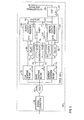
- Fig. 1 shows a diagram of a prior art multi-wire gas filled proportional counter and its associated electronics processing chain
- Fig. 2 shows a diagram of an embodiment of the invention as a gas-filled multi-wire ionization chamber attached to a preamplifier and a digital signal processor and counter;
- Fig. 3 shows preamplifier output traces of charge signals induced on the anode during the collection of two ionization tracks emitted from the sample wall of the detector shown in Fig. 2 ;
- Fig. 4 repeats Fig. 3 for two ionization tracks emitted from the backwall of the detector shown in Fig. 2 ;
- Fig. 5 shows a block diagram of the digital signal processor 50
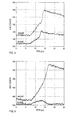
- Fig. 6A shows a scatter plot of 10-to-90% pulse risetime versus pulse amplitude for a series of signals measured from a source placed at two locations (on the sample wall and on the backwall) within the detector shown in Fig. 2 ;
- Fig. 6B shows a scatter plot of initial pulse slope versus pulse amplitude for the same set of signals as in Fig. 6A ;
- Fig. 6C shows a scatter plot of initial pulse slope divided by pulse amplitude versus pulse amplitude for the same set of signals as in Fig. 6A ;
- Fig. 6D repeats Fig. 6C , adding signals from a source on the detector side wall;
- Fig. 7 shows a diagram of a preferred embodiment of the invention wherein guard electrodes have been added to the gas-filled multi-wire ionization chamber shown in Fig. 2 ;
- Fig. 8 shows preamplifier output traces of charge signals induced on the guard and anode electrodes during the collection of an ionization track emitted from the sidewall of the detector shown in Fig. 7 ;
- Fig. 9 repeats Fig. 8 for an ionization track emitted from the sample wall, where the track approaches the sidewall but does not deposit any charge on the guard electrode;
- Fig. 10 shows an embodiment of the invention as a gas-filled parallel plate ionization chamber with guard electrodes added surrounding its anode;
- Figs. 11A and 11B define distances for alpha tracks emitted from the sample and anode planes and shown analytic solutions for the induced charge signals produced as they are collected;
- Fig. 12 shows a preferred embodiment of the invention as a gas filled, parallel plate ionization chamber with guard electrodes, field shaping electrodes, and reduced anode capacitance;
- Fig. 13 shows typical preamplifier output traces of charge signals induced on the anode during the collection of one ionization track emitted from the sample wall of the detector shown in Fig. 12 and one ionization track emitted from the detector's backwall;
- Fig. 14 shows a scatter plot of pulse risetime versus pulse amplitude for a series of 10,000 ionization tracks emitted from the sample wall and 10,000 ionization tracks emitted from the anode backwall for the detector shown in Fig. 12
- the invention exploits the differences in preamplifier pulse features that result from collecting ionization tracks generated by alpha particles emitted from different surfaces within the counter, and uses pulse feature analysis to recognize these differences and so distinguish between alpha particles emitted from the sample and "background" particles emitted from the surfaces of the counter itself.
- the term "region of emanation" denotes the region within the chamber volume where the ionization track originates.
- the region of emanation is where the alpha particle enters the chamber, e.g., window 4 in Fig. 1 .
- the region of emanation is the sample itself.
- the ionization track within the chamber is considered to have a region of emanation corresponding to the sample region, i.e. the region of the chamber volume at or near which a sample is to be located.
- its region of emanation is named after the region from which it is emitted.
- the alpha particle ionization track emanates from the sample region or from another chamber surface, it is convenient to also associate the region of emanation with the preamplifier pulse that results from collecting the track charge on either the anode or guard electrode.
- the pulse when we refer to the pulse as having a region of emanation; this is merely shorthand for the region where the alpha particle's ionization track originated in the chamber.
- Tertiary methods to further enhance the performance of the parallel-plate design by increasing the uniformity of its electric field, reducing the capacitance of its anode, and employing low alpha emitter construction materials are also described.
- ⁇ 2 presents the multi-wire gas filled counter, including guard wires
- ⁇ 3 presents the parallel plate design, including guard electrodes
- ⁇ 4 discusses detector operational issues.
- Fig. 2 shows an embodiment of the invention as a multi-wire counter 30 comprising a manifold 33 containing an anode 40 of multiple wires separated by distance 42 S and sealed by a plate 35 upon which the same sample 20 as in Fig. 1 rests.
- This design differs from the counter of Fig. 1 as follows.
- the anode wire diameter is 5 to 10 times larger (e.g. 0.40 mm) so that, at operating voltage, the counter operates in the ionization chamber mode and not in proportional counter mode. This causes the charges induced on the anode by ionization tracks drifting within the chamber to be sensitive to the ionization track's origin and drift path.
- R max is the range of the most energetic alpha particle expected
- the manifold is sized so that the distance R from sample 20 to the anode 40 is significantly longer (typically 25-30%) than R max and the distance B to the backwall 44 is only a fraction (typically 1/3 to 1/4)of R.
- conventional detectors may sometimes be similarly dimensioned, they are not designed so with the express intention of producing different charge collection times for particles originating from different locations within the chamber.
- the chamber is operated in flow mode, with connections 47 and 49 allowing the entrance and departure of the operating gas, shown here as nitrogen. In this embodiment, the sample is therefore within the counter volume.
- the bias and electronics for the counter of Fig. 2 are identical to those used with the detector of Fig. 1 , and are identically numbered.
- the amplifier 13, discriminator 15, and counter 16 of Fig. 1 are replaced by a digital processor and counter 50.
- the counter is operated in ionization chamber mode, with voltage V 8 chosen so that the time t eR required for an electron to cross R from sample 20 to the anode 40 is a few tens of microseconds.
- the diameter of the anode 40 wires is then chosen so that no charge multiplication occurs in its vicinity.
- the difference between lengths B and R is important to the counter's operation.
- the electron transit time t es across a distance s biased by a voltage V scales as s 2 /V in the parallel plate approximation.
- R/B is, for example, 3
- t eR will be 9 times the transit time t eB across B from the chamber backwall 44 to the anode.
- t eR was chosen to be a few tens of microseconds, so t eB is only a few microseconds, a significant difference.
- the fields in wire chambers are not uniform, but distort in the region of the anode wires.
- S is relatively small, of order 10% of R
- the electric field will be uniform over most of R, becoming non-uniform only within distances comparable to S from the anode allowing the difference between t eR and t eB to be maintained.
- An ionization track 23 created by an alpha particle 22 emitted from the sample 20 ends a distance R' from the anode 40.
- R' is always larger than zero by design, since R is greater than R max .
- this charge drifts in the uniform field, it induces a linearly increasing charge on the anode. Once collected, it ceases to induce any further charge. Close to the anode wires however, the signal shape is difficult to predict accurately. Whether the final result is an upward signal curvature, as shown in the trace 51 in Fig. 2 , or a downward curvature depends in some detail on the length of the track, its angle to the sample, the spacing of the anode wires, and the applied voltage.
- Fig. 3 shows two sample source alpha traces from a multi-wire counter which had B and R values of 1.5 cm and 3.5 cm, respectively. While this ratio is less than ideal, compared to the specifications of Fig. 2 , it is still adequate for the purpose.
- a small 241 Am alpha source was placed within the chamber at the center of the sample region and traces were recorded using a digital signal processor with trace capture capability, the XIA DGF-4C.
- the two traces have significantly different shapes, per the discussion of the previous paragraph. However, their total charge collection times are identical, about 8.0 ⁇ s, and their initial slopes are comparable, being about 25 charge units/ ⁇ s.
- An alpha particle emitted from the backwall 44 creates an ionization track 25 ending a distance R ⁇ from the anode 40, where R ⁇ may be either positive or negative, depending upon the total track length and its angle of emission from the backwall.
- Initial charge collection will be much faster for these signals, both because the field E B in the backwall region is much higher and because any charge in the vicinity of the anode wires will also be collected rapidly due to the high fields in this region. Only charges deposited well into the source side volume will be initially collected more slowly and, by construction, this amount of charge is limited.
- the maximum collection times for backwall signals will come from tracks that penetrate maximally into the source side volume and, by construction, these times will always be less than about half t eR .
- Fig. 4 shows two backwall traces obtained by placing the alpha source on the detector backwall surface.
- the two collection times are different, but both (2.5 and 3.3 ⁇ s, respectively) are over two times faster than the sample wall collection times.
- Initial slopes are about 100 charge units/ ⁇ s, four times larger than in the sample wall case.
- charge collection times and initial slope values are fully adequate to discriminate between signal pulses according to their points of emanation in our preferred embodiment and detailed signal shape descriptions are not required.
- all signals generated by alphas emanating from the sample wall will share two characteristics.
- their total charge collection time is invariant and is given by t eR , since at least some track charge is created immediately next to the sample surface.
- t eR is about a factor of about 9 less than the typical value of t eB from backside collection and at least 25% smaller than the slowest collection from the relatively rare anode source events.
- charge collection time pulse risetime
- the slope test can be improved by dividing So by the total track charge Q T , as the ratio S 0 /Q T depends only on E R at the point of emanation, whereas So also depends upon the track charge and may vary if different energy alpha particles are present.
- the ratio S 0 /Q T becomes superior to So as a test for discriminating point of emanation when the range of alpha particle energies present within the chamber becomes large enough so that the smallest backwall So (the smallest backwall track charge times E B ) overlaps the largest sample wall So (the largest sample charge times E R ) and the simple So test can no longer unambiguously resolve the emanation point in all cases.
- Fig. 5 shows a block diagram of a digital processing circuit 50 that can perform the pulse shape analysis operations to determine alpha particles' points of emanation.
- the circuit comprises a section of analog signal conditioning circuitry 60 feeding an ADC 62 whose output is connected to a fast combinatorial logic circuit 64 implemented in a field programmable gate array (FPGA) that also accepts input from a clock 65 and has an output data bus 66 attached to a DSP 67.
- I/O lines 68 connect the DSP to an external interface to display the processed data or send them to an external computer for further processing, display, and/or storage as may be required.
- the circuit topology is similar to that described in the U.S. Patent of Warburton and Zhou [WARBURTON - 1999] and the issues associated with its operation will be familiar to those skilled in the art of digital spectroscopy.
- the ADC signal is split into three paths, going to a fast triangular shaping circuit 70, an intermediate peaking time triangular shaping circuit 72, and a long peaking time, trapezoidal "energy" filter 74.
- the fast shaper 70 detects pulse signals in the preamplifier output. A peaking time of 400 ns worked well for the signals shown in Figs. 3 and 4 .
- the intermediate triangular shaper measures the signals' initial slopes. Since a slope measurement after about 1 ⁇ s was found to give good differentiation between the two kinds of signals in Figs. 3 and 4 , we set this shaper's peaking time to 1 ⁇ s, and capture its output value about 1 ⁇ s after the pulse is detected.
- the gap time t g for the slow "energy” filter 74 is set to be as long as the slowest risetime signal to be measured, 8 ⁇ s in the present case. Its peaking time t p is not critical, since energy resolution in gas detectors is limited by charge induction fluctuations and not electronic noise. In the work shown, 4 ⁇ s was used, but values from 1 to 8 ⁇ s also work acceptably.
- the word "energy” has been placed in quotation marks because this actually only measures the pulses' amplitudes, which also strongly depend upon charge collection times. However, by convention, we will often refer to this as an energy measurement and, by extension, often speak of the "energy” of a pulse with the understanding that we have really only measured its amplitude.
- the fast shaper 70 feeds a discriminator 76 that has two outputs: a pulse output 77 that goes high for one clock cycle when the fast shaper output first exceeds threshold, and a level output 78 which goes high at the same time, but stays high as long as the fast shaper output exceeds threshold.
- the level output 78 gates timer 80, which counts pulses from the clock 65 to measure time T 82 above threshold, which is then our measurement of the total charge collection time.
- Pulse output 77 is delayed for 1 ⁇ s by delay 89 and then gates slope output register 88 to capture the output of the intermediate triangular shaper 72 as a measurement of the signal pulse's initial slope.
- Pulse output 77 is also delayed for time t p + t g by delay 90 to trigger energy output register 92 to capture the output of the trapezoidal energy filter 74 as a measure of the signal pulse's amplitude.
- This delayed pulse 94 can also be used to interrupt the DSP 67, signaling it that a pulse has been detected and that captured time, slope, and energy values can be read from the timer 80 and output registers 88 and 92 over the data bus 66.
- the DSP 67 completes the measurement by applying cuts (inequality tests) to the measured charge collection time and initial slope (or initial slope divided by energy) to identify the pulse as having originated at the sample or backwall and then, if desired, producing energy spectra for either or both types of pulses.
- the energy filter for example, would produce more accurate results if its gap were matched to the pulse risetime on a pulse-by-pulse basis.
- Fig. 6 shows results for 1000 pulses each from a typical source wall location and a typical back wall location.
- Fig. 6A plots pulse risetime versus final pulse amplitude. As Fig. 6A shows, pulses from the two locations separate fairly cleanly into two distinct regions for pulses with amplitude above about 50.
- the logical test "(IF(pulse amplitude greater than 50) AND (IF(pulse risetime greater than The greater greater 4.5))" discriminates against back wall events with 98-99% accuracy, allowing the counter background from these events to be reduced by two orders of magnitude.
- Fig. 6B shows initial pulse slope, measured over the first microsecond of the pulse, plotted against pulse amplitude for the same set of signals as in Fig. 6A .
- Data from the two sources separates even more cleanly into two regions than in Fig. 6A , but a more complex logical test is required to separate them, since pulse slope is clearly proportional to pulse amplitude. Therefore, in Fig. 6C we plot initial pulse slope divided by final pulse amplitude versus final pulse amplitude. This plot very cleanly differentiates between the two different sources of ionization tracks.
- Fig. 6D shows 1000 events from a source located on the detector side wall overlaid on the plot of Fig. 6C . These events, depending upon their ionization track trajectories, can clearly be mistaken for either source wall or sample wall events. Additional means to discriminate against sidewall pulses would therefore be beneficial.
- sidewall area will be comparable to backwall area.
- Dimension B plus R will typically be about 10 cm.
- the backwall area will then be 1225 cm 2 , compared to the sidewalls' area of 1400 cm 2 .
- Fig. 2 shows the track 26 of an alpha particle emanating from the sidewall, headed toward the sample. Tracks like this will generate signals similar to signals from tracks emanating from the sample. Tracks that actually hit the sample will produce identical tracks. Similarly, tracks headed toward the backwall produce signals similar or identical to backwall signals. Sidewall tracks are thus extremely variable and are not easily separated using the tests applied to Fig. 6C .
- Fig. 7 repeats Fig. 2 , but modified by the addition of a guard wire 100 that surrounds the perimeter of the anode.
- This guard wire may either be in the same plane as the anode 40 or separated slightly from it, as shown.
- the guard wire 100 is biased similarly to the anode 40 via resistor 107 from voltage source 8 and connected to preamplifier 111 via capacitor 110.
- Preamplifier signals are then fed into a second digital processor 150.
- the digital processor 150 is a stripped down version of digital processor 50, lacking (by reference to Fig. 5 ) the clock 65, shaping filter 72, slope output register 88, DSP 67, and the control lines 68 and 94.
- guard wire processor 150 takes its clock signal from anode processor 50, so they run synchronously, and its data bus is an extension of the anode processor's data bus 66 so that the anode processor's DSP 67 can record values captured by the timer and energy output register in the guard wire processor.
- Fig. 8 shows such a pair of traces.
- the anode trace rises in about 5 ⁇ s, which might or might not pass the risetime test as a sample emission pulse.
- the significant guard wire signal could easily be used to identify this as sidewall emission pulse and reject it.
- the breaks in the two curves occur as charges are first collected on the guard wire and then on the anode and cease inducing charge on the other electrode.
- Fig. 9 shows a trace from this source location where no net charge is collected on the guard wire. The anode trace clearly passes both collection time and initial slope tests as a sample signal. A simple discriminator test on the guard wire signal, however, would reject it.
- Fig. 7 Our preferred embodiment as a multi-wire gas counter is therefore the design in Fig. 7 , which has sets of both anode and guard wires, each set having its own preamplifier and signal processor, as shown.
- the test for a good sample signal is that its charge collection time must exceed a first threshold AND its initial (slope/amplitude) must lie below a second threshold AND there is no guard wire veto signal, where a valid veto signal comprises having the veto wire collection time exceed a third threshold AND the veto energy exceed a fourth threshold.
- the four threshold values will be set to optimize performance based on the amplitudes of these signals for expected alpha particle energies and the observed noise properties of the preamplifier circuits.
- Multi-wire counters are often operated with proportional gain, since this produces larger signals, but these signals are only produced as charge actually arrives at the anode (or guard) wires. Since, in detectors with the drift field asymmetry of Fig. 7 , charge collection times will generally be slower for ionization tracks originating from the sample than from the backwall the invention method can still be applied to increase backwall event rejection. However, since collection times will be modified by track orientation, poorer rejection will result than in the preferred embodiment. Sidewall event rejection using guard wire signals will still be good.
- Our second preferred embodiment as a parallel plate ionization chamber offers three practical advantages. First, with proper plate design, the microphonics disappear. Second, by embedding the plates in their supporting medium, it becomes possible to design a detector which may merely be cleaned if it becomes contaminated, rather than having to be rebuilt. Third, for large area detectors, parallel plates have lower capacitance than a wire array of the same area, which increases signal to noise ratios, simplifies preamplifier design, and increases detector sensitivity.
- Fig. 10 shows a first embodiment of our invention as a parallel plate ionization chamber that is quite similar to the Fig. 7 design, except that the guard wires 100 and anode wires 40 have been replaced by a guard strip 200 and anode collection plate 205. The rest of the design is identical and identical part identification numbers have been used to emphasize this.
- the signals produced in this detector will be generally similar to chose produced in the Fig. 5 detector and similar means may be employed to distinguish between ionization tracks emanating from the sample and chamber backwall and to reject those emanating from the chamber sidewalls. Moreover, since the electric field can be nearly uniform everywhere within the chamber, the charge collection signals can be expressed analytically to optimize attainable rejection margins.
- Fig. 10 shows a first ionization track of length ⁇ s emanating from the sample at angle ⁇ and a second track of length ⁇ a emanating from the anode at angle ⁇ , their points of maximum extent lying distances d s and d a from the anode plane, respectively, R being the anode-to-sample separation.
- the electron charge is e, and C f is the preamplifier feedback capacitor.
- the parallel plate ionization chamber shown in Fig. 10 becomes our preferred parallel plate embodiment with the addition of the following three improvements.
- Fig. 10 The geometry of the detector Fig. 10 will not have truly uniform electric fields in its interior because the plates are too far apart, compared to their lateral dimensions and different fields result in different charge collection times which and reduce rejection margins. Increasing the guard electrodes' width W would increase field uniformity, but at the cost of greatly increasing the chamber's active volume. In our preferred embodiment, Fig. 12 , we have therefore added a field shaping electrode 210 surrounding the parallel plate chamber 30.
- This electrode can be easily manufactured, for example, as a series of stripes 212 on a printed circuit board 214, each attached to a node on a resistor divider chain, 215 which is connected to the voltage source V 8 at its anode end via an isolating resistor 217 and capacitor 218, and to ground via a lead 212 at its sample end.
- Equal valued resistors in the divider chain 215 cause the voltage at the surface of the shaping electrode 210 to smoothly pass from V at its anode end to ground at its sample end, which, in turn, forces the electric field a short distance into the chamber to lie parallel to the shaping electrode's surface, provided the chamber manifold 33 is made of a non-conducting material.
- Fig. 13 shows typical signals from sample wall 20 and anode backwall 205 ionization tracks. For equal alpha particle energies they are very different.
- the sample wall trace is three times larger than the backwall trace and has nearly three times the risetime, 28 ⁇ s compared to 10 ⁇ s. These differences make the two emission sources very easy to separate.
- Fig. 14 shows a scatter plot of 10,000 Am-241 sample wall traces and an additional 10,000 anode backwall traces
- the shown risetime cut at 18 places only 24 backwall traces and about 75 sample traces on the wrong side of the line.
- the 24 backwall correspond to a rejection ratio of 99.76%.
- the 75 lost counts correspond to a 99.25% counting efficiency.
- More complex data cuts using both risetime and amplitude information can do much better (e.g. the cut between risetime equals 30 and pulse amplitude equals 1500 yields a rejection ratio of 99.95%), but even the simple cut illustrates the invention's basic principle.
- the entire counter must operate within a grounded enclosure, comprising a cover 233 and a base plate 235. This enclosure is kept a distance R 2 ⁇ R from the anode 205, to minimize added anode capacitance and resultant preamplifier input noise.
- the inside of the parallel plate chamber using low alpha emitting materials.
- the preferred embodiment requires only two materials within the chamber: the chamber wall material itself and the anode/guard conductor material.
- plastics work well for the chamber material, being naturally low Z materials and not prone to alpha emitter contamination.
- the anode electrodes including certain stainless steels [KNOLL - 1989, pp. 724-725] or ultra-low alpha emitting N. [BROWNE - 1999]
- either the anode, 205 guard electrode, 200 or the sample mounting surface 35 can be made out of semiconductor grade Si, which is hyper pure and still has adequate conductivity for the purpose.
- Measurement chambers become contaminated by the materials they measure. With prior art systems, this is tolerated up to a point and then the detector chamber has to be rebuilt.
- Our parallel plate design may be constructed so that its internal surfaces are Smooth and free of cracks and crevices which would trap contaminating materials and so can be easily cleaned if contaminated.
- the anode and guard strip electrodes can be embedded into the plastic of their chamber wall support surface by heating the plastic into a semi-molten state or they may be applied to the chamber wall material as very thin layers by vapor deposition.
- the counter chamber becomes contaminated during the course of operation, it may be cleaned by simple washing procedures. This is an important benefit, as it allows the detector to be employed with a wider range of sample materials than might otherwise be risked.
- the atmosphere typically contains Ra at about 2.4 pCi/liter or 320 d/l-hr. [KNOLL -1989, pg. 725] This would produce an initial counting rate of about 1.2 alpha particles per second (4200/hour) in our 13 liter chamber volume. Purging the chamber to remove atmospheric O 2 therefore has the important secondary benefit of flushing most of the radon and its daughter products from the chamber.
- Thin windows make it difficult to operate prior art multi-wire counters.
- the sample has to be close to the windows since the range of alpha particles in air is very limited, but tearing or puncturing the window means rebuilding the detector.
- solid samples are placed directly inside the chamber, avoiding both alpha absorption losses in the atmosphere and the issues associated with thin windows. Chamber purging times are only a few minutes and typically insignificant compared to the counting times required for very low activity samples.
- the method could be applied to many existing alpha counters, since their internal geometries are typically not symmetrical and, even operated in proportional mode, they produce recognizable differences between particles originating from different interior locations.
- the results might not be comparable to results from a specifically designed detector, but they might offer a significant improvement over purely passive operation.
- the described counters all had rectangular geometries, while cylindrical or, indeed, arbitrary geometries could be employed.
- traces could instead be digitized and processed equivalently using an off-line computer.
Landscapes
- Physics & Mathematics (AREA)
- Health & Medical Sciences (AREA)
- Life Sciences & Earth Sciences (AREA)
- General Physics & Mathematics (AREA)
- High Energy & Nuclear Physics (AREA)
- Molecular Biology (AREA)
- Spectroscopy & Molecular Physics (AREA)
- Measurement Of Radiation (AREA)
- Electron Tubes For Measurement (AREA)
Claims (37)
- Verfahren zum Betreiben eines gasgefüllten Alphazählers, der Folgendes enthält: eine gasgefüllte Kammer mit einem Probengebiet, eine in der Kammer angeordnete Anode zum Sammeln von Ladungen in der Kammer, einen mit der Anode verbundenen Vorverstärker zum Empfangen der darauf gesammelten Ladung und eine Spannungsquelle, die konfiguriert ist, bei Verwendung eine Vorspannung der Art an die Anode anzulegen, dass immer dann, wenn durch ein Alphateilchen, das durch das Gas in der Kammer hindurchtritt, eine Ionisationsspur erzeugt wird, die Elektronen in der Spur von der Anode gesammelt werden und von dem Vorverstärker empfangen werden, um zu bewirken, dass der Vorverstärker einen mit dem Alphateilchen assoziierten Anodenausgangssignalimpuls erzeugt, wobei die Kammer und die Anode so konfiguriert sind, dass von verschiedenen Oberflächen des Zählers emanierende Ionisationsspuren charakteristisch verschiedene Anodenausgangssignalimpulse erzeugen, wobei das Verfahren für mindestens einige Impulse folgendes umfasst:Messen eines oder mehrerer Merkmale des Anodenausgangssignalimpulses, die je nach der Emanationsoberfläche des mit dem Anodenausgangssignalimpuls assoziierten Alphateilchens differieren; undBestimmen der Emanationsoberfläche des mit dem Anodenausgangssignalimpuls assoziierten Alphateilchens auf der Basis der Messung des einen oder der mehreren Merkmale des Anodenausgangssignalimpulses.
- Verfahren nach Anspruch 1 und weiterhin umfassend das Zurückweisen des Impulses als Hintergrund, falls bestimmt wird, dass das assoziierte Alphateilchen des Impulses nicht von einer dem Probengebiet entsprechenden Oberfläche emanierte.
- Verfahren nach Anspruch 1, wobei mindestens einer der Mess- und Bestimmungsschritte durch analoge Verarbeitungsschaltungen ausgeführt wird.
- Verfahren nach Anspruch 1, wobei das Vorverstärkerausgangsignal durch einen Analog-Digital-Wandler konditioniert und digitalisiert wird und mindestens einer der Mess- und Bestimmungsschritte durch digitale Verarbeitungsschaltungen ausgeführt wird.
- Verfahren nach Anspruch 1, wobei:das Probengebiet ein spezifiziertes Gebiet innerhalb der Kammer ist;das Probenmaterial, dessen Alphaemissionsrate bestimmt werden soll, innerhalb des Probengebiets platziert wird undfalls das Probenmaterial innerhalb des Zählers migrieren und ihn so kontaminieren kann, das Probenmaterial daran gehindert wird, indem es mit einem Materialstück bedeckt wird, das dick genug ist, um die Migration zu verhindern, aber dünn genug, um das leichte Eindringen der Alphateilchen in das Volumen des Zählers zu gestatten.
- Verfahren nach Anspruch 1, wobei:das Probengebiet ein Gebiet der Kammer bei einem Stück Fenstermaterial ist, dass dünn genug ist, um das leichte Eindringen von von außerhalb der Kammer kommenden Alphateilchen durch das Materialstück in die Kammer zu gestatten; unddas Probenmaterial, dessen Alphaemissionsrate bestimmt werden soll, außerhalb der Kammer platziert wird und durch das Stück Fenstermaterial davon getrennt ist.
- Verfahren nach Anspruch 1, wobei die Unterschiede bei dem einen oder den mehreren Anodenimpulsmerkmalen, die von der Emanationsoberfläche des Impulses abhängen, übertrieben werden, indem der Zähler so konstruiert oder betrieben wird, dass einer oder mehrere der folgenden Bedingungen erfüllt sind:der Zähler arbeitet im Ionisationsmodus;im Wesentlichen unterschiedliche elektrische Sammelfelder werden bei verschiedenen Oberflächen der Alphateilchenemanationen erzeugt;im Wesentlichen verschiedene Ladungssammelabstände werden bei den verschiedenen Oberflächen der Alphateilchenemanation erzeugt;das eine oder die mehreren Elektrodenelemente, die die Anode umfassen, werden in der Kammer asymmetrisch platziert;Ionisationsspuren, die von den verschiedenen Oberflächen emanieren, benötigen zum Sammeln unterschiedliche Zeitdauern; undIonisationsspuren, die von den verschiedenen Oberflächen emanieren, generieren unterschiedliche Mengen an induzierter Ladung in der Anode, während sie gesammelt werden.
- Verfahren nach Anspruch 1, wobei die Kammer Seitenwände aufweist und weitere Informationen über die Emanationsoberfläche eines Alphateilchens erhalten werden durch:Bereitstellen einer Schutzelektrode in der Nähe der Seitenwände, wodurch ein zusätzlicher Vorverstärker an die Schutzelektrode gekoppelt wird;Vorspannen der Schutzelektrode, so dass immer dann, wenn ein von einer der Seitenwände emanierendes Alphateilchen eine Ionisationsspur erzeugt, ein Teil der Elektronen in der Spur von der Schutzelektrode gesammelt wird und bewirkt, dass der zusätzliche Vorverstärker einen Schutzausgangssignalimpuls erzeugt; undfür mindestens einige der gemessenen Anodenausgangssignalimpulse:auch Messen eines oder mehrerer Merkmale der Schutzausgangssignalimpulse von dem zusätzlichen Vorverstärker, die je nach der Emanationsoberfläche des Schutzausgangssignalimpulses differieren;Bestimmen auf der Basis der Messung des einen oder der mehreren Merkmale des Schutzimpulses, ob die assoziierte Ionisationsspur von einer der Seitenwände emanierte; undZurückweisen aller Alphateilchen als Hintergrund, deren assoziierte Ionisationsspuren als von einer der Seitenwände emanierend identifiziert werden.
- Verfahren nach Anspruch 8, wobei das eine oder die mehreren Merkmale des Schutzimpulses mindestens eines der Folgenden enthalten:die Ankunftszeit des Schutzausgangssignalimpulses relativ zu der des Anodenausgangssignalimpulses unddie finale Änderung bei der Amplitude des Schutzausgangssignalimpulses.
- Verfahren Anspruch 9, wobei für das zurückzuweisende Alphateilchen der Schutzausgangssignalimpuls zusammen mit dem Anodenausgangssignalimpuls ankommen muss und
die auf der Schutzelektrode gesammelte Gesamtladungsmenge einen Schwellwert übersteigen muss. - Verfahren nach Anspruch 8, wobei:die Anode aus ungefähr innerhalb einer Ebene liegenden Drähten besteht;die Kammer teilweise von zwei nominell parallelen Wänden begrenzt ist, von denen eine mit dem Probengebiet assoziiert ist;die Anodendrahtebene nominell parallel zu den Wänden verläuft, aber dadurch asymmetrisch platziert ist, dass sie sich signifikant näher an einer Wand als an der anderen Wand befindet; unddie Schutzelektrode einen oder mehrere zusätzliche Drähte umfasst, die den Umfang der Anodendrähte einschließen und etwa in der gleichen Ebene liegen.
- Verfahren nach Anspruch 8, wobei die Anode und das Probegebiet beides Ebenen sind, ungefähr parallel zueinander und durch einen Abstand getrennt, der signifikant länger ist als die Reichweite der in der Kammer anzutreffenden energiereichsten Alphateilchen; und
die Schutzelektrode den Umfang der Anode umgibt und in der gleichen oder ungefähr der gleichen Ebene wie die Anode liegt. - Verfahren nach Anspruch 12, wobei eine zusätzliche feldformende Elektrodenstruktur gewendet wird, um die Gleichförmigkeit des elektrischen Felds in dem Volumen zwischen der Anode und dem Probengebiet zu vergrößern.
- Verfahren nach Anspruch 12, wobei die Anode und die Schutzelektrode so bündig innerhalb einer stützenden Isolatorstruktur eingebettet sind, dass die resultierende Verbundstruktur frei von Rissen und Hohlräumen ist und leicht gesäubert werden kann, um solche kontaminierenden Materialien zu entfernen, die sich möglicherweise im Verlauf eines Zählerbetriebs anhäufen.
- Verfahren nach Anspruch 1, wobei das eine oder die mehreren Merkmale des Anodenimpulses mindestens eines der Folgenden enthalten:die Dauer des Impulses;die Amplitude des Impulses;die Steigung des Impulses unddie Steigung des Impulses, dividiert durch seine Amplitude.
- Verfahren nach Anspruch 15, wobei die Dauer von einem Zeitgeber gemessen wird, der von einem Diskriminator getaktet wird, dessen Ausgangssignal immer dann auf H geht, wenn sein Eingangssignal einen voreingestellten Schwellwert übersteigt, wobei das Eingangssignal zu dem Diskriminator das Vorverstärkersignal ist, dass von einem Shaping-Filter gefiltert wird, dessen Zeitkonstante im Vergleich zu einer typischen Impulsanstiegszeit schnell ist.
- Verfahren nach Anspruch 15, wobei die Steigung durch ein mittelwertbildendes Differenziator-Filter gemessen wird, dessen Ausgangssignal kurz nach dem anfänglichen Detektieren des Impulses erfasst wird.
- Verfahren nach Anspruch 15, wobei die Impulsamplitude unter Verwendung eines Trapezfilters gemessen wird, dessen Lücke so eingestellt ist, dass sie die längste erwartete Impulsanstiegszeit von 0 auf 100 % übersteigt, und dessen Ausgangssignal zu einer vorbestimmten Zeit nach dem anfänglichen Detektieren des Impulses erfasst wird.
- Verfahren nach Anspruch 15, wobei die Impulsamplitude gemessen wird, indem der Wert eines mittelwertbildenden Filters kurz nach dem Detektieren des Impulsmaximums erfasst und von diesem Wert ein Ausgangswert des gleichen mittelwertbildenden Filters subtrahiert wird, der kurz vor dem anfänglichen Detektieren des Impulses erfasst wird.
- Verfahren nach Anspruch 1, wobei die Hintergrundzählrate weiter reduziert wird, indem der Alphazähler aus Materialien mit niedrigen Alphateilchen-Emissionsraten konstruiert wird.
- Alphateilchenzähler, der folgendes umfasst:eine gasgefüllte Kammer mit einem Probengebiet;eine in der Kammer angeordnete Anode zum Sammeln von Ladungen in der Kammer;einen mit der Anode verbundenen Vorverstärker zum Empfangen der darauf gesammelten Ladung;eine Spannungsquelle, die konfiguriert ist, bei Verwendung eine Vorspannung der Art an die Anode anzulegen, dass immer dann, wenn durch ein Alphateilchen, das durch das Gas in der Kammer hindurchtritt, eine Ionisationsspur erzeugt wird, die Elektronen in der Spur von der Anode gesammelt werden und von dem Vorverstärker empfangen werden, um zu bewirken, dass der Vorverstärker ein mit dem Alphateilchen assoziierten Anodenausgangssignalimpuls erzeugt,wobei die Kammer und die Anode so konfiguriert sind, dass von verschiedenen Oberflächen des Zählers emanierende Ionisationsspuren charakteristisch verschiedene Anodenausgangssignalimpulse erzeugen, und ein primärerImpulsmerkmalsanalysierer, der konfiguriert ist zum:Messen des einen oder der mehreren Merkmale eines Anodenausgangssignalimpulses, die je nach der Emanationsoberfläche differieren; undBestimmen der Oberfläche in der Kammer, von der die durch die Alphateilchen erzeugte Ionisationsspur emanierte, auf der Basis der Messung des einen oder der mehreren Merkmale des Anodenausgangssignalimpulses.
- Zähler nach Anspruch 21, wobei der primäre Impulsmerkmalsanalysierer weiterhin konfiguriert ist zum Zurückweisen des Impulses als Hintergrund, falls er bestimmt, dass das assoziierte Alphateilchen des Impulses nicht von dem Probengebiet emanierte, wodurch die Hintergrundzählrate des Zählers reduziert wird.
- Zähler nach Anspruch 21, wobei der Zähler eines oder mehrerer der folgenden Merkmale hinsichtlich Konstruktion oder Betrieb aufweist, die dazu dienen, die Unterschiede bei den Anodenimpulsmerkmalen zu erzeugen oder zu übertreiben:der Betrieb erfolgt im Ionisationsmodus;es gibt wesentlich unterschiedliche elektrische Sammelfelder bei den verschiedenen Gebieten der Alphateilchenemanation;es gibt wesentlich verschiedene Ladungssammelabstände bei den verschiedenen Gebieten der Alphateilchenemanation;eines oder mehrere der Elektrodenelemente, die die Anode umfassen, sind in der Kammer asymmetrisch platziert;Ionisationspuren von den verschiedenen Gebieten der Alphateilchenemanation weisen im Wesentlichen unterschiedliche Ladungssammelzeiten auf; undIonisationspuren von den verschiedenen Gebieten erzeugen im Wesentlichen verschiedene Mengen an induzierter Ladung in der Anode, während sie gesammelt werden.
- Zähler nach Anspruch 21, wobei der Zähler Seitenwände aufweist, und weiterhin umfassend:eine Schutzelektrode in der Nähe der Seitenwände; einen mit der Schutzelektrode verbundenen zusätzlichen Vorverstärker;eine zusätzliche Spannungsquelle, die die Schutzelektrode so vorspannt, dass die Schutzelektrode Elektronen von Ionisationsspuren sammelt und der zusätzliche Vorverstärker Schutzausgangssignalimpulse erzeugt; undeinen sekundären Impulsmerkmalsanalysierer, der:das eine oder die mehreren Merkmale der Schutzausgangssignalimpulse misst;auf der Basis der Messung des einen oder der mehreren Merkmale der Schutzimpulse zusätzliche Informationen über die Oberfläche bestimmt, von der das assoziierte Alphateilchen des Impulses emanierte; undden Impuls als Hintergrund zurückweist, falls er bestimmt, dass das assoziierte Alphateilchen des Impulses von einer der Kammerseitenwände emanierte, wodurch die Hintergrundzählrate des Zählers reduziert wird.
- Zähler nach Ansprüchen 24, wobei der sekundäre Impulsmerkmalsanalysierer das Alphateilchen zurückweist, wenn er bestimmt, dass:der Schutzausgangssignalimpuls zusammen mit dem Anodenausgangssignalimpuls ankam unddie auf der Schutzelektrode gesammelte Gesamtladungsmenge einen Schwellwert überstieg.
- Zähler nach Anspruch 24, wobei:die Anode aus ungefähr innerhalb einer Ebene liegenden Drähten besteht;die Kammer teilweise von zwei nominell parallelen Wänden begrenzt ist, von denen eine mit dem Probengebiet assoziiert ist;die Ebene, in der die Anodendrähte liegen, nominell parallel zu den Wänden verläuft, aber dadurch asymmetrisch platziert ist, dass sie sich signifikant näher an einer der Wände als an der anderen der Wände befindet; unddie Schutzelektrode einen oder mehrere zusätzliche Drähte umfasst, die den Umfang der Anodendrähte einschließen und etwa in der gleichen Ebene liegen.
- Verfahren nach Anspruch 24, wobei die Anode und das Probegebiet beides Ebenen sind, ungefähr parallel zueinander und durch einen Abstand getrennt, der signifikant länger ist als die Reichweite der in der Kammer anzutreffenden energiereichsten Alphateilchen; und
die Schutzelektrode den Umfang der Anode umgibt und in der gleichen oder ungefähr der gleichen Ebene wie die Anode liegt. - Verfahren nach Anspruch 26 und weiterhin umfassend eine zusätzliche feldformende Elektrodenstruktur, die die Gleichförmigkeit des elektrischen Felds in dem Volumen zwischen der Anode und dem Probengebiet vergrößert.
- Verfahren nach Anspruch 21, wobei der primäre Impulsmerkmalsanalysierer Mittel enthält zum Bestimmen eines oder mehrerer der Folgenden:der Dauer des Impulses;der Amplitude des Impulses;der Steigung des Impulses undder Steigung des Impulses, dividiert durch seine Amplitude.
- Zähler nach Anspruch 29, wobei der primäre Impulsmerkmalsanalysierer die Impulsdauer bestimmt unter Verwendung:eines Shaping-Filters, dessen Zeitkonstante signifikant kürzer ist als die einer typischen Impulsanstiegszeit;eines Diskriminators, dessen Ausgangssignal immer dann auf H geht, wenn sein Eingangssignal von dem Shaping-Filter einen voreingestellten Schwellwert übersteigt;undeines Zeitgebers, der durch das Ausgangssignal des Diskriminators getaktet wird.
- Zähler nach Anspruch 29, wobei der primäre Impulsmerkmalsanalysierer die Steigung bestimmt unter Verwendung:eines mittelwertbildenden Differentiationsfilters undvon Mitteln zum Erfassen des Ausgangssignals des Filters kurz nach dem anfänglichen Detektieren des Impulses.
- Zähler nach Anspruch 29, wobei der primäre Impulsmerkmalsanalysierer die Impulsamplitude bestimmt unter Verwendung:eines Trapezfilters, dessen Lücke so eingestellt ist, dass sie die längste erwartete Impulsanstiegszeit von 0 auf 100 % übersteigt ; undvon Mitteln zum Erfassen des Ausgangssignals des Filters zu einer vorbestimmten Zeit nach dem anfänglichen Detektieren des Impulses.
- Zähler nach Anspruch 21 und weiterhin umfassend:einen Analog-Digital-Wandler zum Digitalisieren des Vorverstärkerausgangssignals und eine digitale Signalverarbeitungsschaltung, die den primären Impulsmerkmalsanalysierer ganz oder teilweise implementiert.
- Zähler nach Anspruch 33, wobei die digitale Signalverarbeitungsschaltung mindestens Folgendes umfasst:einen Verknüpfungslogiksatz, der Impulsmerkmalsanalyseoperationen mit der Taktgeschwindigkeit des Analog-Digital-Wandlers ausführt; undeine digitale Recheneinrichtung, die Impulsmerkmalsanalyseoperationen mit der Impulsereignisrate ausführt.
- Zähler nach Anspruch 21, wobei das in der Kammer verwendete Gas Stickstoff ist.
- Zähler nach Anspruch 21, wobei der Zähler vor dem Start des Zählens mit Stickstoff gespült wird, um Radon und seine Zersetzungsprodukte zu beseitigen.
- Zähler nach Anspruch 21, wobei das Probenmaterial, dessen Alphaemissionsrate bestimmt werden soll, innerhalb eines spezifizierten Gebiets innerhalb der Kammer platziert ist, und
falls das Probenmaterial innerhalb des Zählers migrieren und ihn so kontaminierten kann, dass Probenmaterialmit einem Materialstück bedeckt wird, dass dick genug ist, um die Migration zu verhindern, aber dünn genug, damit die Alphateilchen ohne weiteres in das Volumen des Zählers eindringen können.
Applications Claiming Priority (3)
| Application Number | Priority Date | Filing Date | Title |
|---|---|---|---|
| US09/938,136 US6732059B2 (en) | 2001-08-23 | 2001-08-23 | Ultra-low background gas-filled alpha counter |
| US938136 | 2001-08-23 | ||
| PCT/US2002/026839 WO2003019206A1 (en) | 2001-08-23 | 2002-08-22 | Ultra-low background gas-filled alpha counter |
Publications (3)
| Publication Number | Publication Date |
|---|---|
| EP1419397A1 EP1419397A1 (de) | 2004-05-19 |
| EP1419397A4 EP1419397A4 (de) | 2011-06-08 |
| EP1419397B1 true EP1419397B1 (de) | 2013-06-05 |
Family
ID=25470956
Family Applications (1)
| Application Number | Title | Priority Date | Filing Date |
|---|---|---|---|
| EP02757333.6A Expired - Lifetime EP1419397B1 (de) | 2001-08-23 | 2002-08-22 | Gasgefüllter alphazähler mit ultraniedrigem hintergrund |
Country Status (4)
| Country | Link |
|---|---|
| US (1) | US6732059B2 (de) |
| EP (1) | EP1419397B1 (de) |
| JP (1) | JP4667746B2 (de) |
| WO (1) | WO2003019206A1 (de) |
Families Citing this family (29)
| Publication number | Priority date | Publication date | Assignee | Title |
|---|---|---|---|---|
| JP3741006B2 (ja) * | 2001-08-08 | 2006-02-01 | 株式会社日立製作所 | 荷電粒子測定装置およびその測定方法 |
| US7277511B2 (en) * | 2002-05-15 | 2007-10-02 | Intellon Corporation | Two-stage non-linear filter for analog signal gain control in an OFDM receiver |
| US7105831B1 (en) * | 2003-04-09 | 2006-09-12 | The United States Of America As Represented By The Secretary Of The Army | Ambient air alpha particles ionization detector |
| US6943712B1 (en) | 2003-11-06 | 2005-09-13 | Marvell International Ltd. | Voltage built-in real-time digital non-linearity measurement device and method for analog to digital converters |
| US20050194541A1 (en) * | 2004-03-03 | 2005-09-08 | Clark Brett M. | Large area ionization detector and methods for detecting low level radiation |
| US7564039B1 (en) * | 2004-06-17 | 2009-07-21 | Integrated Sensors, Llc | Dual substrate plasma panel based ionizing radiation detector |
| US7525098B2 (en) * | 2006-04-05 | 2009-04-28 | Orbotech Ltd. | High resolution energy detector |
| US7528377B2 (en) * | 2006-12-26 | 2009-05-05 | Orbotech Medical Solutions Ltd. | Radiation detector circuit |
| US8158449B2 (en) * | 2008-10-08 | 2012-04-17 | International Business Machines Corporation | Particle emission analysis for semiconductor fabrication steps |
| US8374814B2 (en) * | 2011-02-16 | 2013-02-12 | Rigaku Corporation | X-ray detection signal processing apparatus and method therefor |
| JP4880077B1 (ja) * | 2011-02-16 | 2012-02-22 | 株式会社リガク | X線検出信号処理装置および方法 |
| US9012865B2 (en) * | 2012-05-01 | 2015-04-21 | Canberra Industries, Inc. | Radiation detector system and method |
| JP2016522891A (ja) * | 2013-04-24 | 2016-08-04 | コーニンクレッカ フィリップス エヌ ヴェKoninklijke Philips N.V. | 訂正手段を備えたパルス処理回路 |
| EP2990832A1 (de) * | 2014-08-29 | 2016-03-02 | Sercel | Datenbesschaffungsvorrichtung mit einer lokalen Einzeltaktuhr |
| US11646190B2 (en) | 2017-07-21 | 2023-05-09 | Atonarp Inc. | Current detection device and spectrometer using the same |
| US11417509B2 (en) | 2017-07-21 | 2022-08-16 | Atonarp Inc. | Current detection device and spectrometer using ihe same |
| US10224192B2 (en) * | 2017-07-21 | 2019-03-05 | Atonarp Inc. | High-speed low-noise ion current detection circuit and mass spectrometer using the same |
| US10367667B2 (en) * | 2017-09-29 | 2019-07-30 | Nxp B.V. | Joint ad-hoc signal and collision detection method |
| CN109839656B (zh) * | 2019-02-22 | 2022-12-13 | 成都理工大学 | 一种基于α粒子事件读出的数字反符合HPGe谱仪系统 |
| DE102019104710B4 (de) * | 2019-02-25 | 2023-04-27 | Ketek Gmbh | Verfahren zum Betreiben eines Strahlungsdetektionssystems und Strahlungsdetektionssystem |
| CN110333179B (zh) * | 2019-07-10 | 2021-06-15 | 中国科学院近代物理研究所 | 一种深空带电粒子探测器触发方法 |
| CN110441599B (zh) * | 2019-07-15 | 2021-05-28 | 深圳市鼎阳科技股份有限公司 | 一种用于频谱仪的检波方法和装置、可读存储介质 |
| CN110658549B (zh) * | 2019-10-15 | 2023-04-07 | 中国工程物理研究院材料研究所 | 一种本底中弱信号信噪比提升方法及应用 |
| CN113433581B (zh) * | 2021-06-25 | 2022-12-30 | 中国科学技术大学 | 一种低本底的α、β射线探测装置 |
| CN114662419B (zh) * | 2022-03-09 | 2026-02-03 | 中广核工程有限公司 | 核电厂功率运行工况下管道沉积源项本底评估系统及方法 |
| CN115201887A (zh) * | 2022-06-23 | 2022-10-18 | 深圳市计量质量检测研究院 | 一种超低本底α粒子探测器及α粒子的测量方法 |
| CN116338758B (zh) * | 2023-01-03 | 2026-01-09 | 中国原子能科学研究院 | 一种正比计数器的处理方法 |
| DE102025102590B3 (de) * | 2025-01-24 | 2026-01-15 | Berthold Technologies Gmbh & Co. Kg | Gerät und System zum Messen einer Alpha-Strahlungsaktivität und einer Beta-Strahlungsaktivität von radioaktiven Aerosolen künstlichen Ursprungs |
| CN120370376B (zh) * | 2025-06-26 | 2025-09-02 | 北京大学 | 一种测量(n, α)反应角度微分截面的方法 |
Family Cites Families (14)
| Publication number | Priority date | Publication date | Assignee | Title |
|---|---|---|---|---|
| US3869608A (en) * | 1949-10-05 | 1975-03-04 | Scherbatskoy Serge Alexander | Nuclear well logging |
| US3721825A (en) | 1970-12-03 | 1973-03-20 | J Rasmussen | Method and apparatus for analysis of liquid residues using nuclear reactions |
| US4104523A (en) * | 1976-10-06 | 1978-08-01 | Martin Marietta Corporation | Electronic alpha particle counter |
| US4317038A (en) * | 1980-03-24 | 1982-02-23 | Agence Nationale De Valorisation De La Recherche | Device for determining the spatial distribution of radiation |
| JPS57158576A (en) * | 1981-03-27 | 1982-09-30 | Hitachi Ltd | Radiant ray measuring device |
| DE3129431C2 (de) * | 1981-07-25 | 1984-02-09 | FAG Kugelfischer Georg Schäfer KGaA, 8720 Schweinfurt | Einrichtung zum gleichzeitigen Messen von α- und β-Strahlen mit einem im β-Plateau betriebenen Proportionalzählrohr, einem linearen Vorverstärker und zwei Impulshöhendiskriminatoren |
| JPH01102885U (de) * | 1987-12-26 | 1989-07-11 | ||
| JPH0432144A (ja) * | 1990-05-25 | 1992-02-04 | Toshiba Corp | 特性可変型電離箱 |
| DE4021617C2 (de) * | 1990-07-06 | 1993-12-02 | Kugelfischer G Schaefer & Co | Vorrichtung zum kontinuierlichen Messen des Eisengehaltes in Zinkschichten |
| US5059803A (en) | 1990-07-19 | 1991-10-22 | The United States Of America As Represented By The Secretary Of The Army | Rugged alpha particle counter |
| US5192868A (en) * | 1991-08-07 | 1993-03-09 | Tennelec/Nucleus Inc. | Proportional counter detector |
| US5525804A (en) * | 1995-02-01 | 1996-06-11 | The Regents Of The University Of California | Background canceling surface alpha detector |
| US5873054A (en) | 1995-08-14 | 1999-02-16 | William K. Warburton | Method and apparatus for combinatorial logic signal processor in a digitally based high speed x-ray spectrometer |
| DE69631165T2 (de) * | 1995-08-14 | 2004-09-02 | Warburton, William K., Menlo Park | Verfahren und vorrichtung für digitales hochgeschwindigkeits-röntgenspektrometer |
-
2001
- 2001-08-23 US US09/938,136 patent/US6732059B2/en not_active Expired - Lifetime
-
2002
- 2002-08-22 EP EP02757333.6A patent/EP1419397B1/de not_active Expired - Lifetime
- 2002-08-22 JP JP2003524020A patent/JP4667746B2/ja not_active Expired - Fee Related
- 2002-08-22 WO PCT/US2002/026839 patent/WO2003019206A1/en not_active Ceased
Also Published As
| Publication number | Publication date |
|---|---|
| WO2003019206A1 (en) | 2003-03-06 |
| EP1419397A4 (de) | 2011-06-08 |
| JP4667746B2 (ja) | 2011-04-13 |
| US20030040877A1 (en) | 2003-02-27 |
| US6732059B2 (en) | 2004-05-04 |
| EP1419397A1 (de) | 2004-05-19 |
| JP2005501261A (ja) | 2005-01-13 |
Similar Documents
| Publication | Publication Date | Title |
|---|---|---|
| EP1419397B1 (de) | Gasgefüllter alphazähler mit ultraniedrigem hintergrund | |
| US5231290A (en) | Neutron coincidence detectors employing heterogeneous materials | |
| US9885674B2 (en) | Method and device for recognition of a material making use of its transmission function | |
| GB2316744A (en) | Nuclear spectroscopy signal processing system | |
| Fricke et al. | Single particle counting of heavy ions with a channeltron detector | |
| US4264816A (en) | Ionization chamber | |
| US5907156A (en) | Wide range radiation detector | |
| Craig et al. | ‘Blind time’–current limitations on laser ablation multi-collector inductively coupled plasma mass spectrometry (LA-MC-ICP-MS) for ultra-transient signal isotope ratio analysis and application to individual sub-micron sized uranium particles | |
| CN118915123A (zh) | 一种快中子探测器、探测装置及探测方法 | |
| Schneider et al. | Mass-identification of alpha-particles and heavy ions by time-of-flight methods | |
| US5026988A (en) | Method and apparatus for time of flight medium energy particle scattering | |
| Downie et al. | High-resolution position-sensing resistive anode microchannel plate detector systems suitable for megahertz count-rates | |
| US6627898B2 (en) | Method and system for monitoring radiation and rejecting noise | |
| Pansky et al. | Applications of gaseous electron counting detectors | |
| Agnetta et al. | GREX/COVER_PLASTEX: an experiment to analyze the space-time structure of extensive air showers produced by primary cosmic rays of 1015 eV | |
| US4629897A (en) | Automatic high insulation switch | |
| US7791018B2 (en) | Electronic read-out circuits for pixilated/resistive charge detectors | |
| Beghini et al. | A compact parallel plate detector for heavy ion reaction studies | |
| US3435207A (en) | Apparatus for measuring velocity of low energy electrons | |
| Mazur et al. | Position sensitive multiwire proportional parallel plate detector for heavy ions | |
| Padmore et al. | A fast multianode detector for solid state ultraviolet photoelectron spectroscopy | |
| Baldini et al. | The AMS time of flight system | |
| Van Sambeek et al. | A Recoil Detector for electron scattering experiments with internal targets | |
| Tanaka et al. | Beta-spectroscopy of low level samples by a coincidence type scintillation spectrometer | |
| Abazov et al. | Comparative analysis of the performance characteristics of mini-drift tubes with different design |
Legal Events
| Date | Code | Title | Description |
|---|---|---|---|
| PUAI | Public reference made under article 153(3) epc to a published international application that has entered the european phase |
Free format text: ORIGINAL CODE: 0009012 |
|
| 17P | Request for examination filed |
Effective date: 20040309 |
|
| AK | Designated contracting states |
Kind code of ref document: A1 Designated state(s): AT BE BG CH CY CZ DE DK EE ES FI FR GB GR IE IT LI LU MC NL PT SE SK TR |
|
| AX | Request for extension of the european patent |
Extension state: AL LT LV MK RO SI |
|
| A4 | Supplementary search report drawn up and despatched |
Effective date: 20110506 |
|
| 17Q | First examination report despatched |
Effective date: 20110718 |
|
| GRAP | Despatch of communication of intention to grant a patent |
Free format text: ORIGINAL CODE: EPIDOSNIGR1 |
|
| GRAS | Grant fee paid |
Free format text: ORIGINAL CODE: EPIDOSNIGR3 |
|
| GRAA | (expected) grant |
Free format text: ORIGINAL CODE: 0009210 |
|
| RIN1 | Information on inventor provided before grant (corrected) |
Inventor name: WAHL, JOHN Inventor name: WARBURTON, WILLIAM, K. Inventor name: MOMAYEZI, MICHAEL |
|
| AK | Designated contracting states |
Kind code of ref document: B1 Designated state(s): AT BE BG CH CY CZ DE DK EE ES FI FR GB GR IE IT LI LU MC NL PT SE SK TR |
|
| AX | Request for extension of the european patent |
Extension state: AL LT LV MK RO SI |
|
| REG | Reference to a national code |
Ref country code: GB Ref legal event code: FG4D |
|
| REG | Reference to a national code |
Ref country code: CH Ref legal event code: EP |
|
| REG | Reference to a national code |
Ref country code: AT Ref legal event code: REF Ref document number: 615957 Country of ref document: AT Kind code of ref document: T Effective date: 20130615 |
|
| REG | Reference to a national code |
Ref country code: IE Ref legal event code: FG4D |
|
| RAP2 | Party data changed (patent owner data changed or rights of a patent transferred) |
Owner name: WARBURTON, WILLIAM K. |
|
| RIN2 | Information on inventor provided after grant (corrected) |
Inventor name: WARBURTON, WILLIAM, K. Inventor name: MOMAYEZI, MICHAEL Inventor name: WAHL, JOHN |
|
| REG | Reference to a national code |
Ref country code: DE Ref legal event code: R096 Ref document number: 60245076 Country of ref document: DE Effective date: 20130801 |
|
| REG | Reference to a national code |
Ref country code: NL Ref legal event code: T3 |
|
| REG | Reference to a national code |
Ref country code: AT Ref legal event code: MK05 Ref document number: 615957 Country of ref document: AT Kind code of ref document: T Effective date: 20130605 |
|
| PG25 | Lapsed in a contracting state [announced via postgrant information from national office to epo] |
Ref country code: ES Free format text: LAPSE BECAUSE OF FAILURE TO SUBMIT A TRANSLATION OF THE DESCRIPTION OR TO PAY THE FEE WITHIN THE PRESCRIBED TIME-LIMIT Effective date: 20130916 Ref country code: GR Free format text: LAPSE BECAUSE OF FAILURE TO SUBMIT A TRANSLATION OF THE DESCRIPTION OR TO PAY THE FEE WITHIN THE PRESCRIBED TIME-LIMIT Effective date: 20130906 Ref country code: SE Free format text: LAPSE BECAUSE OF FAILURE TO SUBMIT A TRANSLATION OF THE DESCRIPTION OR TO PAY THE FEE WITHIN THE PRESCRIBED TIME-LIMIT Effective date: 20130605 Ref country code: AT Free format text: LAPSE BECAUSE OF FAILURE TO SUBMIT A TRANSLATION OF THE DESCRIPTION OR TO PAY THE FEE WITHIN THE PRESCRIBED TIME-LIMIT Effective date: 20130605 Ref country code: FI Free format text: LAPSE BECAUSE OF FAILURE TO SUBMIT A TRANSLATION OF THE DESCRIPTION OR TO PAY THE FEE WITHIN THE PRESCRIBED TIME-LIMIT Effective date: 20130605 |
|
| REG | Reference to a national code |
Ref country code: LT Ref legal event code: MG9D |
|
| PG25 | Lapsed in a contracting state [announced via postgrant information from national office to epo] |
Ref country code: BG Free format text: LAPSE BECAUSE OF FAILURE TO SUBMIT A TRANSLATION OF THE DESCRIPTION OR TO PAY THE FEE WITHIN THE PRESCRIBED TIME-LIMIT Effective date: 20130905 |
|
| PG25 | Lapsed in a contracting state [announced via postgrant information from national office to epo] |
Ref country code: SK Free format text: LAPSE BECAUSE OF FAILURE TO SUBMIT A TRANSLATION OF THE DESCRIPTION OR TO PAY THE FEE WITHIN THE PRESCRIBED TIME-LIMIT Effective date: 20130605 Ref country code: PT Free format text: LAPSE BECAUSE OF FAILURE TO SUBMIT A TRANSLATION OF THE DESCRIPTION OR TO PAY THE FEE WITHIN THE PRESCRIBED TIME-LIMIT Effective date: 20131007 Ref country code: EE Free format text: LAPSE BECAUSE OF FAILURE TO SUBMIT A TRANSLATION OF THE DESCRIPTION OR TO PAY THE FEE WITHIN THE PRESCRIBED TIME-LIMIT Effective date: 20130605 Ref country code: CZ Free format text: LAPSE BECAUSE OF FAILURE TO SUBMIT A TRANSLATION OF THE DESCRIPTION OR TO PAY THE FEE WITHIN THE PRESCRIBED TIME-LIMIT Effective date: 20130605 |
|
| PLBE | No opposition filed within time limit |
Free format text: ORIGINAL CODE: 0009261 |
|
| STAA | Information on the status of an ep patent application or granted ep patent |
Free format text: STATUS: NO OPPOSITION FILED WITHIN TIME LIMIT |
|
| PG25 | Lapsed in a contracting state [announced via postgrant information from national office to epo] |
Ref country code: DK Free format text: LAPSE BECAUSE OF FAILURE TO SUBMIT A TRANSLATION OF THE DESCRIPTION OR TO PAY THE FEE WITHIN THE PRESCRIBED TIME-LIMIT Effective date: 20130605 Ref country code: MC Free format text: LAPSE BECAUSE OF FAILURE TO SUBMIT A TRANSLATION OF THE DESCRIPTION OR TO PAY THE FEE WITHIN THE PRESCRIBED TIME-LIMIT Effective date: 20130605 |
|
| 26N | No opposition filed |
Effective date: 20140306 |
|
| REG | Reference to a national code |
Ref country code: DE Ref legal event code: R097 Ref document number: 60245076 Country of ref document: DE Effective date: 20140306 |
|
| PG25 | Lapsed in a contracting state [announced via postgrant information from national office to epo] |
Ref country code: TR Free format text: LAPSE BECAUSE OF FAILURE TO SUBMIT A TRANSLATION OF THE DESCRIPTION OR TO PAY THE FEE WITHIN THE PRESCRIBED TIME-LIMIT Effective date: 20130605 Ref country code: CY Free format text: LAPSE BECAUSE OF FAILURE TO SUBMIT A TRANSLATION OF THE DESCRIPTION OR TO PAY THE FEE WITHIN THE PRESCRIBED TIME-LIMIT Effective date: 20130605 |
|
| PG25 | Lapsed in a contracting state [announced via postgrant information from national office to epo] |
Ref country code: LU Free format text: LAPSE BECAUSE OF NON-PAYMENT OF DUE FEES Effective date: 20130822 |
|
| REG | Reference to a national code |
Ref country code: FR Ref legal event code: PLFP Year of fee payment: 15 |
|
| REG | Reference to a national code |
Ref country code: FR Ref legal event code: PLFP Year of fee payment: 16 |
|
| REG | Reference to a national code |
Ref country code: FR Ref legal event code: PLFP Year of fee payment: 17 |
|
| PGFP | Annual fee paid to national office [announced via postgrant information from national office to epo] |
Ref country code: BE Payment date: 20190617 Year of fee payment: 18 |
|
| PGFP | Annual fee paid to national office [announced via postgrant information from national office to epo] |
Ref country code: NL Payment date: 20190814 Year of fee payment: 18 |
|
| PGFP | Annual fee paid to national office [announced via postgrant information from national office to epo] |
Ref country code: IT Payment date: 20190821 Year of fee payment: 18 Ref country code: FR Payment date: 20190711 Year of fee payment: 18 Ref country code: DE Payment date: 20190806 Year of fee payment: 18 Ref country code: IE Payment date: 20190813 Year of fee payment: 18 |
|
| PGFP | Annual fee paid to national office [announced via postgrant information from national office to epo] |
Ref country code: GB Payment date: 20190822 Year of fee payment: 18 |
|
| PGFP | Annual fee paid to national office [announced via postgrant information from national office to epo] |
Ref country code: CH Payment date: 20190819 Year of fee payment: 18 |
|
| REG | Reference to a national code |
Ref country code: DE Ref legal event code: R119 Ref document number: 60245076 Country of ref document: DE |
|
| REG | Reference to a national code |
Ref country code: CH Ref legal event code: PL |
|
| REG | Reference to a national code |
Ref country code: NL Ref legal event code: MM Effective date: 20200901 |
|
| GBPC | Gb: european patent ceased through non-payment of renewal fee |
Effective date: 20200822 |
|
| PG25 | Lapsed in a contracting state [announced via postgrant information from national office to epo] |
Ref country code: CH Free format text: LAPSE BECAUSE OF NON-PAYMENT OF DUE FEES Effective date: 20200831 Ref country code: LI Free format text: LAPSE BECAUSE OF NON-PAYMENT OF DUE FEES Effective date: 20200831 |
|
| REG | Reference to a national code |
Ref country code: BE Ref legal event code: MM Effective date: 20200831 |
|
| PG25 | Lapsed in a contracting state [announced via postgrant information from national office to epo] |
Ref country code: FR Free format text: LAPSE BECAUSE OF NON-PAYMENT OF DUE FEES Effective date: 20200831 Ref country code: IT Free format text: LAPSE BECAUSE OF NON-PAYMENT OF DUE FEES Effective date: 20200822 Ref country code: DE Free format text: LAPSE BECAUSE OF NON-PAYMENT OF DUE FEES Effective date: 20210302 |
|
| PG25 | Lapsed in a contracting state [announced via postgrant information from national office to epo] |
Ref country code: BE Free format text: LAPSE BECAUSE OF NON-PAYMENT OF DUE FEES Effective date: 20200831 Ref country code: IE Free format text: LAPSE BECAUSE OF NON-PAYMENT OF DUE FEES Effective date: 20200822 Ref country code: GB Free format text: LAPSE BECAUSE OF NON-PAYMENT OF DUE FEES Effective date: 20200822 |
|
| PG25 | Lapsed in a contracting state [announced via postgrant information from national office to epo] |
Ref country code: NL Free format text: LAPSE BECAUSE OF NON-PAYMENT OF DUE FEES Effective date: 20200901 |