EP1419675B1 - Kaltschmelztiegel mit induktionserwärmung und wärmerohr-kühlung - Google Patents
Kaltschmelztiegel mit induktionserwärmung und wärmerohr-kühlung Download PDFInfo
- Publication number
- EP1419675B1 EP1419675B1 EP02796300A EP02796300A EP1419675B1 EP 1419675 B1 EP1419675 B1 EP 1419675B1 EP 02796300 A EP02796300 A EP 02796300A EP 02796300 A EP02796300 A EP 02796300A EP 1419675 B1 EP1419675 B1 EP 1419675B1
- Authority
- EP
- European Patent Office
- Prior art keywords
- crucible
- cold crucible
- heat pipes
- cold
- segments
- Prior art date
- Legal status (The legal status is an assumption and is not a legal conclusion. Google has not performed a legal analysis and makes no representation as to the accuracy of the status listed.)
- Expired - Lifetime
Links
Images




Classifications
-
- H—ELECTRICITY
- H05—ELECTRIC TECHNIQUES NOT OTHERWISE PROVIDED FOR
- H05B—ELECTRIC HEATING; ELECTRIC LIGHT SOURCES NOT OTHERWISE PROVIDED FOR; CIRCUIT ARRANGEMENTS FOR ELECTRIC LIGHT SOURCES, IN GENERAL
- H05B6/00—Heating by electric, magnetic or electromagnetic fields
- H05B6/02—Induction heating
- H05B6/22—Furnaces without an endless core
- H05B6/24—Crucible furnaces
-
- H—ELECTRICITY
- H05—ELECTRIC TECHNIQUES NOT OTHERWISE PROVIDED FOR
- H05B—ELECTRIC HEATING; ELECTRIC LIGHT SOURCES NOT OTHERWISE PROVIDED FOR; CIRCUIT ARRANGEMENTS FOR ELECTRIC LIGHT SOURCES, IN GENERAL
- H05B6/00—Heating by electric, magnetic or electromagnetic fields
- H05B6/02—Induction heating
- H05B6/36—Coil arrangements
- H05B6/42—Cooling of coils
Definitions
- the invention lies in the field of fusion certain materials with high melting temperature, such as glass, refractory oxides, oxides metal and some metals, by means of a electromagnetic induction heating. She in particular, the cold crucibles to cooled sectors and direct spinning crucibles.
- FIGS. 1, 2 and 3 Two examples of crucibles used are represented by FIGS. 1, 2 and 3.
- Figure 1 represents a first type of sectorized crucible, used for these purposes. It is consisting mainly of sectors 1, a bottom 2, of an inductor 3 with several turns and a circuit of cooling 4. Sectors 1 are placed vertically, against each other, for to constitute the enclosure of the crucible.
- the complete background 2 this enclosure. It is specified that this background 2 can be retractable or have one or more holes for the evacuation of the materials poured into the crucible.
- the sectors 1 are kept against each other, thanks to a fixation by means of a wrapping 5.
- the cooling circuit 4 is constituted by a arrival 4E and a departure 4S of liquid from cooling, which is, in most cases, the water.
- the crucible thus formed is of a shape usually cylindrical, without it being imperative.
- High intensity alternating current is of the order of a few thousand amps, at a frequency between a few tens of hertz and several megahertz.
- the tension can reach several thousand volts.
- the bottom of crucible 2 can to be cooled or not.
- FIG. 2 shows in section a sector 1, as well as the circulation of water in a pipe 6 and 4E arrival and 4S exit. We aknowledge water circulates along the entire height of sector 1.
- Figure 3 shows another kind of inductor 6, said to direct turn, consisting of a single and cylindrical spire constituting the enclosure directly containing the product to be heated.
- the circuit 7 is here constituted by a spiral surrounding the inductor 6. To close the crucible and to avoid the drawbacks of electrical voltages between the two terminals 6A and 6B of the inductor 6, a cold finger 8 is placed between them.
- the sectors are each made up of one heat pipe with electrically insulated walls constituting the crucible as well as their own ways of cooling.
- each heat pipe preferably has an upper part exceeding the enclosure of the crucible constituted by the low parts from each sector, and deported to the outside. This allows the evacuation of heat by a circulation forced fluid against the upper part of the heat pipes, while allowing access from the top of the crucible.
- the heat pipes of each sector can be extend under the enclosure to form the bottom.
- the bottom can also be consisting of other heat pipes different from those constituting the enclosure of the crucible.
- the inductor is a single turn and direct formed of a ferrule cooled by heatpipes.
- cold fingers may consist of one (or more) heat pipe (s).
- the ferrule of the direct coil can be constituted by the continuous assembly of heat pipes not electrically isolated.
- the thick ferrule constituting the direct spire, can be machined for the realization in located heat pipes.
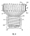
- FIG. materials are always melted into a part similar to that of the crucible described in FIG. formed here of sectors 11 of which part 11B is similar to the plurality of sectors 1 of the crucible of Figure 1.
- Each sector 11 consists of a heat pipe, preferably of cylindrical section, without this form is imperative. She might be cuboid.
- the wall of the heat pipe must be copper or stainless steel, or any other product or metal likely to be suitable for the application considered.
- the coolant contained in the heat pipe constituting a sector 11 may be water or any other suitable fluid, such as sodium, germanium, the money.
- the upper part 11H of each sector 11, where the evacuation of the heat captured in the crucible, is surrounded by a device for forced circulation of a fluid, symbolized via a 14E entrance and a 14S exit, which runs alongside 11H high parts of sectors 11.
- each sector is electrically rendered insulating in its lower part 11B where the sectors 11 adjacent ones are in contact with each other by a suitable coating.
- a suitable coating For example, one thinks of a Plasma or process-sprayed alumina coating PVD.
- the crucible as shown in Figure 4, has a bottom 12 which is, in this case, cooled by extension 11F of sectors 11, below their lower parts 11B.
- bottom 2 might not be cooled and be open in the middle to allow the passage of long pieces or to evacuate the resolidified product.
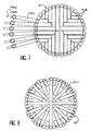
- Figure 7 shows, in bottom view, the same crucible of Figure 4, the bottom 12 being removed.
- the low ends 11B of sectors 11 that extend from the periphery towards the center of the crucible.
- these different low ends 11B of sectors 11 have lengths different, so as to entangle the others like a wooden floor with sticks and to carry out the complete recovery of the bottom.
- the high parts 11H sectors 11 with inputs 14E and outputs 14S from coolant circulation.
- Figure 8 shows another configuration of the lower ends 21B of the sectors 21 for constitute the cooling of the bottom of the crucible.
- each low end 21B is moving towards the center of the crucible, these different lower ends 21B having different lengths to be able, not to entangle, but to cover, roughly speaking, the bottom of the crucible.
- the bottom 22 can also be cooled by heat pipes 24, independent of sectors 21 by penetrating the bottom 22.
- This arrangement is intended, inter alia, where additional inductor 29 is placed under the bottom 22 to provide additional heating of the crucible.
- the independent heat pipes 24 have a high part 24H similar to the upper part 14H of the sectors represented on the crucible of Figure 4, that is to say, deviating from the center of the crucible, beyond the inductor 23.
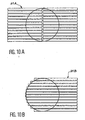
- FIG. 10A and 10B show the heat pipes which can be used under the substance of the crucible.
- the independent heat pipes 21A of FIG. 10A extend on either side of a plane of symmetry of the crucible which has been shown cylindrical.
- the heat pipes 21B each extend over the entire bottom surface and extend only one side of the crucible.
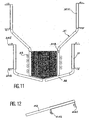
- Figure 11 shows that the lower part crucible can be constituted by heat pipes 32 independent, positioned slightly inclined so as to cover the bottom of the crucible. They complete the sectors 31 placed between the inductor 33 and the crucible itself, the heat being evacuated through the cooling circuit the entrance has been referenced 34E and the exit 34S. This realization is particularly suitable for crucibles cold, sectorized parallelepipedic shape.
- Figure 12 shows that heat pipes 32 of Figure 10 can be replaced by inclined independent heat pipes 42, the circuit cooling being adapted to this geometry, the 44E inputs and 44S outputs no longer found horizontal.
- Figure 13 shows another variant of the crucible according to the invention. Indeed, she shows the superposition of several crucibles to form only one of a significant height, so a increased capacity. In view of the separated form of high parts 51H, sectors 51, the nesting of different crucibles one above the other is possible. It is noted that the lower crucible is equipped independent heat pipes 52, similar to heat pipes 32 of Figure 11. The different successive inductors 53 are equivalent to one much longer inductor that would be constituted in only one part.
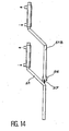
- the fixation of these different crucibles on each other can be performed by means of brazed pimples 57 on each lower end of a central part of the sector 51 and engaging in a fastener 56 attached to the lower end of the lower part 51B of sector 51 of the crucible which is just higher.
- this crucible applies also to a crucible using an inductor constituted of a single turn, like that of Figure 3.
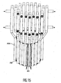
- Figure 15 shows the realization of a direct spin crucible whose ferrule 58 is cooled using the heat pipes 59 attached to it, one or several heat pipe (s) 60 constituting the cold finger.
- a variant embodiment consists in using a ferrule thick in the realization of the direct turn, a adequate machining for the in situ production of heat pipes or simply their insertion.
Landscapes
- Physics & Mathematics (AREA)
- Electromagnetism (AREA)
- General Induction Heating (AREA)
- Crucibles And Fluidized-Bed Furnaces (AREA)
- Furnace Details (AREA)
Claims (13)
- Kaltschmelztiegel mit elektromagnetischer Induktionserwärmung, bestimmt für das Einschmelzen von Glas, refraktären Oxiden und Metallen, hauptsächlich umfassend:dadurch gekennzeichnet, dass die Sektoren (11, 21, 31, 51) durch Wärmerohre mit elektrisch isolierenden Wänden gebildet werden, die selbst die Kühleinrichtungen bilden.einen Boden (2, 22);wenigstens einen Induktor (3, 33, 53); undnebeneinander angeordnete und einen Behälter des Tiegels bildende Sektoren (11, 21, 31, 51);Kühleinrichtungen;
- Kaltschmelztiegel nach Anspruch 1, dadurch gekennzeichnet, dass die Wärmerohre einen oberen Teil (11H, 31H, 51H) aufweisen, der über den durch die unteren Teile (11B, 31B, 51B) aller Sektoren gebildeten Behälter des Tiegels seitlich hinausragt, um die Abführung der Wärme durch eine Fluid-Zwangszirkulation zu ermöglichen, der man den oberen Teil (11H, 31H, 51H) der Sektoren aussetzt.
- Kaltschmelztiegel nach Anspruch 1, dadurch gekennzeichnet, dass die Sektoren (11F) sich unter dem Behälter des Tiegels verlängern, um den Boden zu bilden oder den Boden (12) zu kühlen.
- Kaltschmelztiegel nach Anspruch 1, dadurch gekennzeichnet, dass der Boden des Tiegels durch unabhängige Wärmerohre (24) gebildet wird, die von denen (11, 31, 51) unabhängig sind, die den Behälter des Tiegels bilden.
- Kaltschmelztiegel nach Anspruch 2, dadurch gekennzeichnet, dass er einen Reif (16) zur Befestigung der oberen Teile (11H) der Sektoren (11, 21) umfasst, der elektrisch isolierend ist und alle diese oberen Teile (11H) umgibt.
- Kaltschmelztiegel nach Anspruch 1, dadurch gekennzeichnet, dass die Sektoren (11, 21, 51) durch eine Umwicklung (5) des unteren Teils (11B) der Sektoren verbunden bzw. zusammengehalten werden.
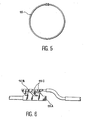
- Kaltschmelztiegel nach Anspruch 1, dadurch gekennzeichnet, dass die Sektoren durch selbsthemmende Ringe (15) verbunden bzw. zusammengehalten werden.
- Kaltschmelztiegel nach Anspruch 1, dadurch gekennzeichnet, dass er einen zusätzlichen Induktor (29) umfasst, der zur Erwärmung des Tiegels unter dem Boden (22) angeordnet ist.
- Kaltschmelztiegel nach Anspruch 2, dadurch gekennzeichnet, dass er mehrere übereinanderliegende Sektorenstufen (51) umfasst, die derart einen langen und hohen Tiegelbehälter bilden und deren induktor durch Induktoren (53) von jeder der so übereinander angeordneten Stufen gebildet wird.
- Kaltschmelztiegel nach Anspruch 1, dadurch gekennzeichnet, dass der Induktor eine einzige und direkte Windung ist, gebildet durch einen Reif (58), gekühlt durch Wärmerohre (59).
- Kaltschmelztiegel nach Anspruch 1 oder 10, dadurch gekennzeichnet, dass der kalte Finger (oder die Finger) durch ein (oder mehrere) Wärmerohr(e) (60) gebildet wird.
- Kaltschmelztiegel nach Anspruch 1 oder 10, dadurch gekennzeichnet, dass der Reif (58) der direkten Windung gebildet wird durch den kontinuierlichen Zusammenbau von elektrisch nicht isolierenden Wärmerohren.
- Kaltschmelztiegel nach Anspruch 1 oder 10, dadurch gekennzeichnet, dass der die direkte Windung bildende dicke Reif für die In-situ-Realisierung der Wärmerohre maschinell bearbeitet wird.
Applications Claiming Priority (3)
| Application Number | Priority Date | Filing Date | Title |
|---|---|---|---|
| FR0111044A FR2828981B1 (fr) | 2001-08-23 | 2001-08-23 | Creuset a chauffage par induction et refroidissement par caloducs |
| FR0111044 | 2001-08-23 | ||
| PCT/FR2002/002914 WO2003019984A1 (fr) | 2001-08-23 | 2002-08-21 | Creuset froid a chauffage par induction et refroidissement par caloducs. |
Publications (2)
| Publication Number | Publication Date |
|---|---|
| EP1419675A1 EP1419675A1 (de) | 2004-05-19 |
| EP1419675B1 true EP1419675B1 (de) | 2005-01-05 |
Family
ID=8866683
Family Applications (1)
| Application Number | Title | Priority Date | Filing Date |
|---|---|---|---|
| EP02796300A Expired - Lifetime EP1419675B1 (de) | 2001-08-23 | 2002-08-21 | Kaltschmelztiegel mit induktionserwärmung und wärmerohr-kühlung |
Country Status (5)
| Country | Link |
|---|---|
| EP (1) | EP1419675B1 (de) |
| JP (1) | JP4610893B2 (de) |
| DE (1) | DE60202534T2 (de) |
| FR (1) | FR2828981B1 (de) |
| WO (1) | WO2003019984A1 (de) |
Cited By (1)
| Publication number | Priority date | Publication date | Assignee | Title |
|---|---|---|---|---|
| WO2014174489A1 (fr) | 2013-04-26 | 2014-10-30 | Commissariat A L'energie Atomique Et Aux Energies Alternatives | Four a chauffage par induction electromagnetique, utilisation du four pour la fusion d'un melange de metal(ux) et d'oxyde(s) representatif d'un corium |
Families Citing this family (13)
| Publication number | Priority date | Publication date | Assignee | Title |
|---|---|---|---|---|
| US7002900B2 (en) | 2002-10-25 | 2006-02-21 | Qualcomm Incorporated | Transmit diversity processing for a multi-antenna communication system |
| US8134976B2 (en) | 2002-10-25 | 2012-03-13 | Qualcomm Incorporated | Channel calibration for a time division duplexed communication system |
| US8320301B2 (en) | 2002-10-25 | 2012-11-27 | Qualcomm Incorporated | MIMO WLAN system |
| US20040081131A1 (en) | 2002-10-25 | 2004-04-29 | Walton Jay Rod | OFDM communication system with multiple OFDM symbol sizes |
| US7986742B2 (en) | 2002-10-25 | 2011-07-26 | Qualcomm Incorporated | Pilots for MIMO communication system |
| US8570988B2 (en) | 2002-10-25 | 2013-10-29 | Qualcomm Incorporated | Channel calibration for a time division duplexed communication system |
| US8169944B2 (en) | 2002-10-25 | 2012-05-01 | Qualcomm Incorporated | Random access for wireless multiple-access communication systems |
| US7324429B2 (en) | 2002-10-25 | 2008-01-29 | Qualcomm, Incorporated | Multi-mode terminal in a wireless MIMO system |
| US8208364B2 (en) | 2002-10-25 | 2012-06-26 | Qualcomm Incorporated | MIMO system with multiple spatial multiplexing modes |
| US9473269B2 (en) | 2003-12-01 | 2016-10-18 | Qualcomm Incorporated | Method and apparatus for providing an efficient control channel structure in a wireless communication system |
| US7466749B2 (en) | 2005-05-12 | 2008-12-16 | Qualcomm Incorporated | Rate selection with margin sharing |
| US8358714B2 (en) | 2005-06-16 | 2013-01-22 | Qualcomm Incorporated | Coding and modulation for multiple data streams in a communication system |
| FR3001856B1 (fr) * | 2013-02-01 | 2017-10-20 | Jacques Boudier | Creuset froid polyphase |
Family Cites Families (6)
| Publication number | Priority date | Publication date | Assignee | Title |
|---|---|---|---|---|
| DD202791A1 (de) * | 1981-07-13 | 1983-09-28 | Horst Seeber | Kuehlbare induktionsspule nach dem prinzip des waermerohres |
| DD215681A1 (de) * | 1983-05-17 | 1984-11-14 | Inducal Goellingen Veb | Verlustwaermerueckgewinnung aus induktionsspulen nach dem prinzip des waermerohres |
| DD218983A1 (de) * | 1983-05-17 | 1985-02-20 | Inducal Goellingen Veb | Kuehlbare induktionsspule nach dem prinzip des waermerohres |
| FR2566890B1 (fr) * | 1984-06-29 | 1986-11-14 | Commissariat Energie Atomique | Cage froide pour creuset a fusion par induction electromagnetique a frequence elevee |
| DE19705458A1 (de) * | 1997-02-13 | 1998-08-20 | Leybold Systems Gmbh | Tiegel zum induktiven Schmelzen oder Überhitzen von Metallen, Legierungen oder anderen elektrisch leitfähigen Werkstoffen |
| JPH1174070A (ja) * | 1997-08-28 | 1999-03-16 | Fuji Electric Co Ltd | 浮揚溶解用るつぼ |
-
2001
- 2001-08-23 FR FR0111044A patent/FR2828981B1/fr not_active Expired - Fee Related
-
2002
- 2002-08-21 DE DE60202534T patent/DE60202534T2/de not_active Expired - Lifetime
- 2002-08-21 EP EP02796300A patent/EP1419675B1/de not_active Expired - Lifetime
- 2002-08-21 JP JP2003524302A patent/JP4610893B2/ja not_active Expired - Lifetime
- 2002-08-21 WO PCT/FR2002/002914 patent/WO2003019984A1/fr not_active Ceased
Cited By (1)
| Publication number | Priority date | Publication date | Assignee | Title |
|---|---|---|---|---|
| WO2014174489A1 (fr) | 2013-04-26 | 2014-10-30 | Commissariat A L'energie Atomique Et Aux Energies Alternatives | Four a chauffage par induction electromagnetique, utilisation du four pour la fusion d'un melange de metal(ux) et d'oxyde(s) representatif d'un corium |
Also Published As
| Publication number | Publication date |
|---|---|
| FR2828981A1 (fr) | 2003-02-28 |
| JP2005502018A (ja) | 2005-01-20 |
| DE60202534T2 (de) | 2005-12-29 |
| EP1419675A1 (de) | 2004-05-19 |
| WO2003019984A1 (fr) | 2003-03-06 |
| JP4610893B2 (ja) | 2011-01-12 |
| FR2828981B1 (fr) | 2004-05-21 |
| DE60202534D1 (de) | 2005-02-10 |
Similar Documents
| Publication | Publication Date | Title |
|---|---|---|
| WO2003019984A1 (fr) | Creuset froid a chauffage par induction et refroidissement par caloducs. | |
| FR2638224A1 (fr) | Four de fusion pour traiter les dechets et methode de chauffage de celui-ci | |
| FR2488367A1 (fr) | Valve de figeage comportant plusieurs dispositifs de chauffage et de refroidissement et procede de mise en oeuvre de cette valve | |
| EP0822733A1 (de) | Vorrichtung zum induktiven Erwärmen und kontinuierliche Wärmebehandlungsanlage der solche Vorrichtung verwendet | |
| EP0311506B1 (de) | Schmelztiegel für einen Induktionsofen | |
| CA2901357C (fr) | Four a induction et procede de traitement des dechets metalliques a entreposer | |
| FR2751738A1 (fr) | Four de fusion par induction directe en creuset froid | |
| EP0622140B1 (de) | Steuerungsanlage für den Schmelzausfluss in kalten Tiegelöfen | |
| CA2017132C (fr) | Creuset froid a vidange par le fond | |
| EP0169765A1 (de) | Gekühltes Gefäss für Tiegel mit elektromagnetischem Induktionshochfrequenzschmelzen | |
| CA1092200A (fr) | Four electrique a haute frequence | |
| CH618785A5 (de) | ||
| FR3072768A1 (fr) | Procede et dispositif de moulage notamment d’un verre metallique | |
| CA2569755C (fr) | Installation d'affinage de silicium | |
| CA1251640A (fr) | Dispositif pour l'homogeneisation en temperature de produits metalliques en defilement | |
| FR2566805A1 (fr) | Procede et dispositif pour le revetement de creusets de quartz avec des couches protectrices | |
| CA1086806A (fr) | Poche metallurgique pour les traitements inductifs des metaux | |
| EP0161991A2 (de) | Dichte Panzergehäuse ausgestattet für die Strahlenspektrometrie-Anwendung | |
| EP0685571B1 (de) | Verfahren und Vorrichtung zur Beschichtung eines Substrats mittels Kathodenzerstäubung | |
| FR2638665A1 (fr) | Machine de nettoyage d'objets | |
| EP0441733B1 (de) | Metallurgisches Gefäss mit mindestens einer Elektrode, die durch die Bodenwand geht | |
| EP1077267B1 (de) | Vorrichtung zum Durchlaufwärmebehandeln von metallischen Werkstücken, einzeln oder gruppenweise | |
| WO2012127152A1 (fr) | Creuset de four a induction | |
| BE671580A (de) | ||
| FR2788709A1 (fr) | Procede pour alimenter un creuset a levitation |
Legal Events
| Date | Code | Title | Description |
|---|---|---|---|
| PUAI | Public reference made under article 153(3) epc to a published international application that has entered the european phase |
Free format text: ORIGINAL CODE: 0009012 |
|
| 17P | Request for examination filed |
Effective date: 20040120 |
|
| AK | Designated contracting states |
Kind code of ref document: A1 Designated state(s): AT BE BG CH CY CZ DE DK EE ES FI FR GB GR IE IT LI LU MC NL PT SE SK TR |
|
| AX | Request for extension of the european patent |
Extension state: AL LT LV MK RO SI |
|
| GRAP | Despatch of communication of intention to grant a patent |
Free format text: ORIGINAL CODE: EPIDOSNIGR1 |
|
| RBV | Designated contracting states (corrected) |
Designated state(s): DE FR GB |
|
| GRAS | Grant fee paid |
Free format text: ORIGINAL CODE: EPIDOSNIGR3 |
|
| GRAA | (expected) grant |
Free format text: ORIGINAL CODE: 0009210 |
|
| AK | Designated contracting states |
Kind code of ref document: B1 Designated state(s): DE FR GB |
|
| REG | Reference to a national code |
Ref country code: GB Ref legal event code: FG4D Free format text: NOT ENGLISH |
|
| REF | Corresponds to: |
Ref document number: 60202534 Country of ref document: DE Date of ref document: 20050210 Kind code of ref document: P |
|
| GBT | Gb: translation of ep patent filed (gb section 77(6)(a)/1977) |
Effective date: 20050404 |
|
| PLBE | No opposition filed within time limit |
Free format text: ORIGINAL CODE: 0009261 |
|
| STAA | Information on the status of an ep patent application or granted ep patent |
Free format text: STATUS: NO OPPOSITION FILED WITHIN TIME LIMIT |
|
| 26N | No opposition filed |
Effective date: 20051006 |
|
| REG | Reference to a national code |
Ref country code: GB Ref legal event code: FG4D Free format text: NOT ENGLISH |
|
| REG | Reference to a national code |
Ref country code: FR Ref legal event code: PLFP Year of fee payment: 15 |
|
| REG | Reference to a national code |
Ref country code: FR Ref legal event code: PLFP Year of fee payment: 16 |
|
| REG | Reference to a national code |
Ref country code: FR Ref legal event code: PLFP Year of fee payment: 17 |
|
| PGFP | Annual fee paid to national office [announced via postgrant information from national office to epo] |
Ref country code: FR Payment date: 20210831 Year of fee payment: 20 |
|
| PGFP | Annual fee paid to national office [announced via postgrant information from national office to epo] |
Ref country code: GB Payment date: 20210819 Year of fee payment: 20 Ref country code: DE Payment date: 20210811 Year of fee payment: 20 |
|
| REG | Reference to a national code |
Ref country code: DE Ref legal event code: R071 Ref document number: 60202534 Country of ref document: DE |
|
| REG | Reference to a national code |
Ref country code: GB Ref legal event code: PE20 Expiry date: 20220820 |
|
| PG25 | Lapsed in a contracting state [announced via postgrant information from national office to epo] |
Ref country code: GB Free format text: LAPSE BECAUSE OF EXPIRATION OF PROTECTION Effective date: 20220820 |