EP1419731B1 - Système pour la surveillance du taux de glucose sanguin en utilisant un dispositif médical implantable - Google Patents
Système pour la surveillance du taux de glucose sanguin en utilisant un dispositif médical implantable Download PDFInfo
- Publication number
- EP1419731B1 EP1419731B1 EP03256605A EP03256605A EP1419731B1 EP 1419731 B1 EP1419731 B1 EP 1419731B1 EP 03256605 A EP03256605 A EP 03256605A EP 03256605 A EP03256605 A EP 03256605A EP 1419731 B1 EP1419731 B1 EP 1419731B1
- Authority
- EP
- European Patent Office
- Prior art keywords
- blood glucose
- glucose level
- patient
- glucose levels
- qtc
- Prior art date
- Legal status (The legal status is an assumption and is not a legal conclusion. Google has not performed a legal analysis and makes no representation as to the accuracy of the status listed.)
- Expired - Lifetime
Links
Images




Classifications
-
- A—HUMAN NECESSITIES
- A61—MEDICAL OR VETERINARY SCIENCE; HYGIENE
- A61B—DIAGNOSIS; SURGERY; IDENTIFICATION
- A61B5/00—Measuring for diagnostic purposes; Identification of persons
- A61B5/145—Measuring characteristics of blood in vivo, e.g. gas concentration or pH-value ; Measuring characteristics of body fluids or tissues, e.g. interstitial fluid or cerebral tissue
- A61B5/14532—Measuring characteristics of blood in vivo, e.g. gas concentration or pH-value ; Measuring characteristics of body fluids or tissues, e.g. interstitial fluid or cerebral tissue for measuring glucose, e.g. by tissue impedance measurement
-
- A—HUMAN NECESSITIES
- A61—MEDICAL OR VETERINARY SCIENCE; HYGIENE
- A61B—DIAGNOSIS; SURGERY; IDENTIFICATION
- A61B5/00—Measuring for diagnostic purposes; Identification of persons
- A61B5/24—Detecting, measuring or recording bioelectric or biomagnetic signals of the body or parts thereof
- A61B5/316—Modalities, i.e. specific diagnostic methods
- A61B5/318—Heart-related electrical modalities, e.g. electrocardiography [ECG]
- A61B5/346—Analysis of electrocardiograms
- A61B5/349—Detecting specific parameters of the electrocardiograph cycle
- A61B5/355—Detecting T-waves
-
- A—HUMAN NECESSITIES
- A61—MEDICAL OR VETERINARY SCIENCE; HYGIENE
- A61B—DIAGNOSIS; SURGERY; IDENTIFICATION
- A61B5/00—Measuring for diagnostic purposes; Identification of persons
- A61B5/24—Detecting, measuring or recording bioelectric or biomagnetic signals of the body or parts thereof
- A61B5/316—Modalities, i.e. specific diagnostic methods
- A61B5/318—Heart-related electrical modalities, e.g. electrocardiography [ECG]
- A61B5/346—Analysis of electrocardiograms
- A61B5/349—Detecting specific parameters of the electrocardiograph cycle
- A61B5/36—Detecting PQ interval, PR interval or QT interval
-
- A—HUMAN NECESSITIES
- A61—MEDICAL OR VETERINARY SCIENCE; HYGIENE
- A61N—ELECTROTHERAPY; MAGNETOTHERAPY; RADIATION THERAPY; ULTRASOUND THERAPY
- A61N1/00—Electrotherapy; Circuits therefor
- A61N1/18—Applying electric currents by contact electrodes
- A61N1/32—Applying electric currents by contact electrodes alternating or intermittent currents
- A61N1/36—Applying electric currents by contact electrodes alternating or intermittent currents for stimulation
- A61N1/362—Heart stimulators
- A61N1/37—Monitoring; Protecting
- A61N1/3702—Physiological parameters
Definitions
- the invention relates generally implantable medical devices, such as pacemakers or implantable cardioverter/defibrillators (ICDs), and in particular to implantable medical devices provided with the capability of monitoring blood glucose levels.
- implantable medical devices such as pacemakers or implantable cardioverter/defibrillators (ICDs)
- ICDs implantable cardioverter/defibrillators
- Diabetic patients need to frequently monitor blood glucose levels to ensure that the levels remain within acceptable bounds and, for insulin dependent diabetics, to determine the amount of insulin that must be administered.
- Conventional techniques for monitoring blood glucose levels leave much to be desired.
- One conventional technique for example, requires that the patient draw blood, typically by pricking the finger. The drawn blood is then analyzed by a portable device to determine the blood glucose level. The technique can be painful and therefore can significantly discourage the patient from periodically checking blood glucose levels. Moreover, since an external device is required to analyze the blood, there is the risk that the patient will neglect to keep the device handy, preventing periodic blood glucose level monitoring.
- implantable blood glucose monitors have been developed, which included sensors for mounting directly within the blood stream.
- sensors for mounting directly within the blood stream.
- such monitors have not achieved much success as the glucose sensors tend to clog over very quickly.
- an implantable device that would continually and reliably measure blood glucose levels without requiring glucose sensors would be very desirable.
- risks associated with implanting the blood glucose monitor such as adverse reactions to anesthetics employed during the implantation procedure or the onset of subsequent infections.
- a cardiac stimulation device such as a pacemaker or ICD, it would be desirable to exploit features of electrical cardiac signals routinely detected by the implantable device for use as a proxy to estimate blood glucose levels.
- QTc corrected QT interval
- T-wave amplitude T-wave amplitude
- the invention is directed to providing an implantable cardiac stimulation device with the capability of monitoring blood glucose levels based upon electrocardiographic signals.
- At least one patent (U.S. No. 5,741,211 to Renirie) has alluded to the use of electrocardiographic signal features as a basis for detecting blood glucose levels, particularly QRS and T-waves.
- Renirie discloses a device according to the preamble of claim 1 and primarily directed to a Holter-type external monitor, but has some discussion of implantable devices as well. Renirie mentions the possibility of using other features besides QRS and T-waves such as QT intervals and RR intervals but does not specifically indicate the desirability of combining QT intervals and T-waves.
- Renirie does not appear to be enabling as to the use of T-waves insofar as implantable device monitoring is concerned.
- Renirie describes the use of a standard pacemaker lead for the purposes of measuring T-wave amplitudes.
- the conventional pacemaker lead simply does not appear capable of detecting T-wave amplitudes with the requisite degree of accuracy.
- Renirie fails to even mention the bimodal response of the T-wave amplitude referred to above or to provide any technique for addressing the ambiguities resulting from using T-wave amplitudes as a proxy for blood glucose levels.
- QT intervals are concerned, Renirie makes no mention of employing corrected QT intervals.
- the invention is directed toward overcoming the many technical challenges needed to provide a working system for detecting blood glucose levels via T-waves and QT intervals within an implantable medical device.
- an implantable medical device comprising: a cardiac signal detection unit operative to detect T-waves and QT intervals; and a glucose monitoring system operative to derive blood glucose levels based on a combination of the detected T-waves and the detected QT intervals, wherein the glucose monitoring system is further operative to: convert detected T-waves into t-wave amplitude fractions; convert detected QT intervals into corrected QT (QTc) interval deltas; and to determine the blood glucose level based on a combination of the T-wave amplitude fractions and the QTc deltas.
- the implantable medical device is a pacemaker or ICD.
- blood glucose monitoring is conveniently provided within patients already requiring a pacemaker or ICD, without requiring implantation of additional devices.
- an implantable device to detect blood glucose levels, no external blood-monitoring device is required and no painful finger prick techniques are needed. Hence, there is no risk the patient will fail to periodically detect blood glucose levels.
- blood glucose levels can be detected as often as needed, for example, once every five minutes.
- the implanted device compares the blood glucose level against acceptable upper and lower bounds and appropriate warning signals are generated if the level exceeds the acceptable bounds. If an implantable insulin pump is additionally provided, the insulin pump may be automatically controlled based on the detected blood glucose level to maintain the level within a pre-determined acceptable range.
- T-waves are detected using either a defibrillation coil, an enlarged ventricular lead or a series of smaller leads combined to provided a single strong ventricular signal providing the requisite degree of accuracy in the detection of T-waves.
- T-wave amplitude fraction is derived by inputting a T-wave baseline value, detecting cardiac electrical signals, measuring T-wave amplitude within the cardiac signals, and then converting T-wave amplitude into the T-wave amplitude fraction by subtracting the T-wave baseline value.
- QTc interval is detected by inputting a QT interval baseline value, measuring heart rate based on the cardiac electrical signals, measuring QT interval within the cardiac signals, then converting QT interval into a QTc interval based on the heart rate.
- the QTc interval is then converted into a QT interval delta by subtracting the QT baseline value and the blood glucose level is then determined based on a combination of the T-wave amplitude fraction and the QTc delta value.
- Blood Glucose Level A - B*(QTc delta) - C*(T-wave amplitude fraction) wherein A, B and C are predetermined parameters or coefficients calibrated to the particular patient.
- FIG. 1 illustrates a stimulation device 10 in electrical communication with a patient's heart 12 by way of three leads 20, 24 and 30 suitable for delivering multi-chamber stimulation and shock therapy.
- the stimulation device 10 is coupled to an implantable right atrial lead 20 having at least an atrial tip electrode 22, which typically is implanted in the patient's right atrial appendage.
- the stimulation device 10 is coupled to a "coronary sinus" lead 24 designed for placement in the "coronary sinus region" via the coronary sinus os so as to place a distal electrode adjacent to the left ventricle and additional electrode(s) adjacent to the left atrium.
- coronary sinus region refers to the vasculature of the left ventricle, including any portion of the coronary sinus, great cardiac vein, left marginal vein, left posterior ventricular vein, middle cardiac vein, and/or small cardiac vein or any other cardiac vein accessible by the coronary sinus.
- the coronary sinus lead 24 is designed to receive atrial and ventricular cardiac signals and to deliver left ventricular pacing therapy using at least a left ventricular tip electrode 26, left atrial pacing therapy using at least a left atrial ring electrode 27, and shocking therapy using at least a left atrial coil electrode 28.
- the stimulation device 10 is also shown in electrical communication with the patient's heart 12 by way of an implantable right ventricular lead 30 having, in this embodiment, a right ventricular tip electrode 32, a right ventricular ring electrode 34, a right ventricular (RV) coil electrode 36, and an SVC coil electrode 38.
- the right ventricular lead 30 is transvenously inserted into the heart 12 so as to place the right ventricular tip electrode 32 in the right ventricular apex so that the RV coil electrode 36 will be positioned in the right ventricle and the SVC coil electrode 38 will be positioned in the superior vena cava.
- the right ventricular lead 30 is capable of receiving cardiac signals, and delivering stimulation in the form of pacing and shock therapy to the right ventricle.
- RV coil electrode 36 configured for defibrillation
- RV coil electrode 36 is sufficiently large to reliably measure QTc intervals and the T-wave amplitudes by detecting the voltage between the RV coil and the can.
- a set of smaller RV electrodes can instead be implanted with signals generated therefrom averaged together to yield a single ventricular signal having sufficient accuracy to reliably detect QTc intervals and the T-wave amplitudes.
- the invention is not limited for use only with implanted devices having defibrillator coils but can be implemented within otherwise conventional pacemakers. Further information regarding the accurate detection of QT intervals is provided within "Measurement of High Resolution ECG QT Interval during Controlled Euglycaemia and Hypoglycaemia", Ireland, et al, (Physiol. Meas. Vol. 21, May 2000, pp 295-303), which is incorporated by reference herein.
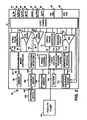
- FIG. 2 illustrates a simplified block diagram of the multi-chamber implantable stimulation device 10 which is capable of treating both fast and slow arrhythmias with stimulation therapy, including cardioversion, defibrillation, and pacing stimulation. While a particular multi-chamber device is shown, this is for illustration purposes only and one of skill in the art could readily duplicate, eliminate or disable the appropriate circuitry in any desired combination to provide a device capable of treating the appropriate chamber(s) with cardioversion, defibrillation and/or pacing stimulation.
- the stimulation device 10 includes a housing 40 which is often referred to as a "can", “case” or “case electrode”, and which may be programmably selected to act as the return electrode for all "unipolar" modes.
- the housing 40 may further be used as a return electrode alone or in combination with one or more of the coil electrodes 28, 36, or 38, for shocking purposes.
- the housing 40 further includes a connector (not shown) having a plurality of terminals, 42,44, 46, 48, 52, 54, 56, and 58 (shown schematically and, for convenience, the names of the electrodes to which they are connected are shown next to the terminals).
- the connector includes at least a right atrial tip terminal 42 adapted for connection to the right atrial (A R ) tip electrode 22.
- the connector includes at least a left ventricular (V L ) tip terminal 44, a left atrial (A L ) ring terminal 46, and a left atrial (A L ) shocking terminal (coil) 48, which are adapted for connection to the left ventricular tip electrode 26, the left atrial ring electrode 27, and the left atrial coil electrode 28, respectively.
- V L left ventricular
- a L left atrial
- a L shocking terminal
- the connector further includes a right ventricular (V R ) tip terminal 52, a right ventricular (V R ) ring terminal 54, a right ventricular (RV) shocking terminal (coil) 56, and an SVC shocking terminal (coil) 58, which are adapted for connection to the right ventricular tip electrode 32, right ventricular ring electrode 34, the RV coil electrode 36, and the SVC coil electrode 38, respectively.
- V R right ventricular
- RV right ventricular
- the microcontroller 60 typically includes a microprocessor, or equivalent control circuitry or processor, designed specifically for controlling the delivery of stimulation therapy, and may further include RAM or ROM memory, logic and timing circuitry, state machine circuitry, and I/O circuitry.
- the microcontroller 60 includes the ability to process or monitor input signals (data) as controlled by program code stored in a designated block of memory.
- the details of the design and operation of the microcontroller 60 are not critical to the present invention. Rather, any suitable microcontroller 60 may be used that carries out the functions described herein.
- the use of microprocessor-based control circuits for performing timing and data analysis functions is well known in the art.
- an atrial pulse generator 70 and a ventricular pulse generator 72 generate pacing stimulation pulses for delivery by the right atrial lead 20, the right ventricular lead 30, and/or the coronary sinus lead 24 via a switch bank 74. It is understood that in order to provide stimulation therapy in each of the four chambers of the heart, the atrial pulse generator 70 and the ventricular pulse generator 72 may include dedicated, independent pulse generators, multiplexed pulse generators, or shared pulse generators. The atrial pulse generator 70 and the ventricular pulse generator 72 are controlled by the microcontroller 60 via appropriate control signals 76 and 78, respectively, to trigger or inhibit the stimulation pulses.
- the microcontroller 60 further includes timing control circuitry 79 which is used to control the timing of such stimulation pulses (e.g., pacing rate, atrio-ventricular (AV) delay, atrial interconduction (A-A) delay, ventricular interconduction (V-V) delay, pacing mode, etc.), as well as to keep track of the timing of refractory periods, PVARP intervals, noise detection windows, evoked response windows, alert intervals, marker channel timing, etc.
- stimulation pulses e.g., pacing rate, atrio-ventricular (AV) delay, atrial interconduction (A-A) delay, ventricular interconduction (V-V) delay, pacing mode, etc.
- the switch bank 74 includes a plurality of switches for connecting the desired electrodes to the appropriate I/O circuits, thereby providing complete electrode programmability. Accordingly, the switch bank 74, in response to a control signal 80 from the microcontroller 60, determines the polarity of the stimulation pulses (e.g., unipolar, bipolar, combipolar, etc.) by selectively closing the appropriate combination of switches (not shown) as is known in the art. If multiple RV electrodes are employed to generate a single averaged ventricular signal, then switch 74 is configured to allow the paralleling (or averaging) of the multiple RV electrodes to simulate a large electrode for accurate sensing of the T-wave.
- polarity of the stimulation pulses e.g., unipolar, bipolar, combipolar, etc.
- Atrial sensing circuits 82 and ventricular sensing circuits 84 may also be selectively coupled to the right atrial lead 20, coronary sinus lead 24, and the right ventricular lead 30, through the switch bank 74, for detecting the presence of cardiac activity in each of the four chambers of the heart. Accordingly, the atrial and ventricular sensing circuits 82 and 84 may include dedicated sense amplifiers, multiplexed amplifiers, or shared amplifiers.
- the switch bank 74 determines the "sensing polarity" of the cardiac signal by selectively closing the appropriate switches. In this way, the clinician may program the sensing polarity independent of the stimulation polarity.
- Each of the sensing circuits, 82 and 84 preferably employ one or more low power, precision amplifiers with programmable gain and/or automatic gain control, bandpass filtering, and a threshold detection circuit, to selectively sense the cardiac signal of interest.
- the automatic gain control enables the stimulation device 10 to deal effectively with the difficult problem of sensing the low amplitude signal characteristics of . atrial or ventricular fibrillation.
- the outputs of the atrial and ventricular sensing circuits 82 and 84 are connected to the microcontroller 60 for triggering or inhibiting the atrial and ventricular pulse generators 70 and 72, respectively, in a demand fashion, in response to the absence or presence of cardiac activity, respectively, in the appropriate chambers of the heart.
- the atrial and ventricular sensing circuits 82 and 84 receive control signals over signal lines 86 and 88 from the microcontroller 60, for controlling the gain, threshold, polarization charge removal circuitry (not shown), and the timing of any blocking circuitry (not shown) coupled to the inputs of the atrial and ventricular sensing circuits 82 and 84.
- the stimulation device 10 utilizes the atrial and ventricular sensing circuits 82 and 84 to sense cardiac signals, for determining whether a rhythm is physiologic or pathologic.
- sensing is reserved for the noting of an electrical signal
- detection is the processing of these sensed signals and noting the presence of an arrhythmia.
- the timing intervals between sensed events are then classified by the microcontroller 60 by comparing them to a predefined rate zone limit (e.g., bradycardia, normal, low rate VT, high rate VT, and fibrillation rate zones) and various other characteristics (e.g., sudden onset, stability, physiologic sensors, and morphology, etc.) in order to determine the type of remedial therapy that is needed (e.g., bradycardia pacing, anti-tachycardia pacing, cardioversion shocks or defibrillation shocks, collectively referred to as "tiered therapy").
- a rate zone limit e.g., bradycardia, normal, low rate VT, high rate VT, and fibrillation rate zones
- various other characteristics e.g., sudden onset, stability, physiologic sensors, and morphology, etc.
- Cardiac signals are also applied to the inputs of an analog-to-digital (A/D) data acquisition system 90.
- the data acquisition system 90 is configured to acquire intracardiac electrogram signals, convert the raw analog data into digital signals, and store the digital signals for later processing and/or telemetric transmission to an external device 102.
- the data acquisition system 90 is coupled to the right atrial lead 20, the coronary sinus lead 24, and the right ventricular lead 30 through the switch bank 74 to sample cardiac signals across any pair of desired electrodes.
- the data acquisition system 90 may be coupled to the microcontroller 60 or other detection circuitry, for detecting an evoked response from the heart 12 in response to an applied stimulus, thereby aiding in the detection of "capture". Capture occurs when an electrical stimulus applied to the heart is of sufficient energy to depolarize the cardiac tissue, thereby causing the heart muscle to contract.
- the microcontroller 60 detects a depolarization signal during a window following a stimulation pulse, the presence of which indicates that capture has occurred.
- the microcontroller 60 enables capture detection by triggering the ventricular pulse generator 72 to generate a stimulation pulse, starting a capture detection window using the timing circuitry within the microcontroller 60, and enabling the data acquisition system 90 via control signal 92 to sample the cardiac signal that falls in the capture detection window and, based on the amplitude of the sampled cardiac signal, determines if capture has occurred.
- the microcontroller 60 is further coupled to a memory 94 by a suitable data/address bus 96, where the programmable operating parameters used by the microcontroller 60 are stored and modified, as required, in order to customize the operation of the stimulation device 10 to suit the needs of a particular patient.
- Such operating parameters define, for example, pacing pulse amplitude, pulse duration, electrode polarity, rate, sensitivity, automatic features, arrhythmia detection criteria, pacing mode, and the amplitude, waveshape and vector of each shocking pulse to be delivered to the patient's heart 12 within each respective tier of therapy.
- a feature of the stimulation device 10 is the ability to sense and store a relatively large amount of data (e.g., from the data acquisition system 90), which data may then be used for subsequent analysis to guide the programming of the stimulation device 10.
- the operating parameters of the stimulation device 10 may be non-invasively programmed into the memory 94 through a telemetry circuit 100 in telemetric communication with the external device 102, such as a programmer, transtelephonic transceiver, or a diagnostic system analyzer.
- the telemetry circuit 100 is activated by the microcontroller 60 by a control signal 106.
- the telemetry circuit 100 advantageously allows intracardiac electrograms and status information relating to the operation of the stimulation device 10 (as contained in the microcontroller 60 or memory 94) to be sent to the external device 102 through an established communication link 104.
- a blood glucose monitoring unit 101 of the microcontroller processes signals representative of QT intervals and T-wave amplitude fractions and, using parameters previously generated by external device 102, derives the current blood glucose level within the bloodstream of the patient. If an insulin pump 103 is provided, the blood glucose monitoring unit transmits control signals to the insulin pump for adjusting the amount of insulin delivered to the patient in view of the current blood glucose levels.
- Information regarding implantable insulin pumps may be found in. U.S. Patent No. 4,731,051 to Fischell and in U.S. Patent No. 4,947,845 to Davis. The insulin pumps discussed therein, or other suitable insulin pumps, are modified as needed to permit receipt of control signals from glucose monitoring unit 101. The operation of the blood glucose monitoring unit is described in detail below with reference to FIG. 4.
- the stimulation device 10 further includes a physiologic sensor 108, commonly referred to as a "rate-responsive" sensor because it is typically used to adjust pacing stimulation rate according to the exercise state of the patient.
- the physiological sensor 108 may further be used to detect changes in cardiac output, changes in the physiological condition of the heart, or diumal changes in activity (e.g., detecting sleep and wake states).
- the microcontroller 60 responds by adjusting the various pacing parameters (such as rate, AV Delay, V-V Delay, etc.) at which the atrial and ventricular pulse generators, 70 and 72, generate stimulation pulses.
- the stimulation device 10 additionally includes a power source such as a battery 110 that provides operating power to all the circuits shown in FIG. 2.
- a power source such as a battery 110 that provides operating power to all the circuits shown in FIG. 2.
- the battery 110 must be capable of operating at low current drains for long periods of time and also be capable of providing high-current pulses (for capacitor charging) when the patient requires a shock pulse.
- the battery 110 must preferably have a predictable discharge characteristic so that elective replacement time can be detected. Accordingly, the stimulation device 10 can employ lithium/silver vanadium oxide batteries.
- the stimulation device 10 further includes a magnet detection circuitry (not shown), coupled to the microcontroller 60.
- the purpose of the magnet detection circuitry is to detect when a magnet is placed over the stimulation device 10, which magnet may be used by a clinician to perform various test functions of the stimulation device 10 and/or to signal the microcontroller 60 that an external programmer 102 is in place to receive or transmit data to the microcontroller 60 through the telemetry circuit 100.
- the stimulation device 10 is shown as having an impedance measuring circuit 112 which is enabled by the microcontroller 60 via a control signal 114.
- an impedance measuring circuit 112 includes, but are not limited to, lead impedance surveillance during the acute and chronic phases for proper lead positioning or dislodgment; detecting operable electrodes and automatically switching to an operable pair if dislodgment occurs; measuring respiration or minute ventilation; measuring thoracic impedance for determining shock thresholds; detecting when the device has been implanted; measuring stroke volume; and detecting the opening of the valves, etc.
- the impedance measuring circuit 112 is advantageously coupled to the switch bank 74 so that any desired electrode may be used.
- the stimulation device 10 It is a primary function of the stimulation device 10 to operate as an implantable cardioverter/defibrillator (ICD) device. That is, it must detect the occurrence of an arrhythmia, and automatically apply an appropriate electrical shock therapy to the heart aimed at terminating the detected arrhythmia. To this end, the microcontroller 60 further controls a shocking circuit 116 by way of a control signal 118.
- the shocking circuit 116 generates shocking pulses of low (up to 0.5 joules), moderate (0.5-10 joules), or high (11-40 joules) energy, as controlled by the microcontroller 60.
- Such shocking pulses are applied to the patient's heart through at least two shocking electrodes, as shown in this embodiment, selected from the left atrial coil electrode 28, the RV coil electrode 36, and/or the SVC coil electrode 38 ( FIG. 1 ).
- the housing 40 may act as an active electrode in combination with the RV electrode 36, or as part of a split electrical vector using the SVC coil electrode 38 or the left atrial coil electrode 28 (e.g., using the RV electrode as a common electrode).
- Cardioversion shocks are generally considered to be of low to moderate energy level (so as to minimize pain felt by the patient), and/or synchronized with an R-wave, and/or pertaining to the treatment of tachycardia.
- Defibrillation shocks are generally of moderate to high energy level (i.e., corresponding to thresholds in the range of 5-40 joules), delivered asynchronously (since R-waves may be too disorganized) and pertaining exclusively to the treatment of fibrillation.
- the microcontroller 60 is capable of controlling the synchronous or asynchronous delivery of the shocking pulses.
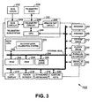
- FIG. 3 illustrates pertinent components of external programmer device 102 for use in programming an implantable medical device such as a pacemaker or ICD.
- the programmer permits a physician or other user to program the operation of the implanted device and to retrieve and display information received from the implanted device such as IEGM data and device diagnostic data.
- the external programmer receives and displays ECG data from separate external ECG leads that may be attached to the patient.
- programmer 102 may also be capable of processing and analyzing data received from the implanted device and from the ECG leads to, for example, render preliminary diagnosis as to medical conditions of the patient or to the operations of the implanted device.
- a CPU 202 which may be a generally programmable microprocessor or microcontroller or may be a dedicated processing device such as an application specific integrated circuit (ASIC) or the like.
- Software instructions to be performed by the CPU are accessed via an internal bus 204 from a read only memory (ROM) 206 and random access memory 230. Additional software may be accessed from a hard drive 208, floppy drive 210, and CD ROM drive 212, or other suitable permanent mass storage device.
- ROM read only memory
- Additional software may be accessed from a hard drive 208, floppy drive 210, and CD ROM drive 212, or other suitable permanent mass storage device.
- a basic input output system BIOS is retrieved from the ROM by CPU at power up. Based upon instructions provided in the BIOS, the CPU "boots up" the overall system in accordance with well-established computer processing techniques.
- the CPU displays a menu of programming options to the user via an LCD display 214 or other suitable computer display device.
- the CPU may, for example, display a menu of specific programming parameters of the implanted device to be programmed or may display a menu of types of diagnostic data to be retrieved and displayed.
- the physician enters various commands via either a touch screen 216 overlaid on the LCD display or through a standard keyboard 218 supplemented by additional custom keys 220, such as an emergency VVI (EVVI) key.
- EVVI key sets the implanted device to a safe VVI mode with high pacing outputs. This ensures life sustaining pacing operation in nearly all situations but by no means is it desirable to leave the implantable device in the EVVI mode at all times.
- Telemetry subsystem 222 includes its own separate CPU 224 for coordinating the operations of the telemetry subsystem.
- Main CPU 202 of programmer communicates with telemetry subsystem CPU 224 via internal bus 204.
- Telemetry subsystem additionally includes a telemetry circuit 226 connected to a telemetry wand 228, which, in turn, receives and transmits signals electromagnetically from a telemetry unit of the implanted device.
- the telemetry wand is placed over the chest of the patient near the implanted device to permit reliable transmission of data between the telemetry wand and the implanted device.
- the external programming device controls the implanted device via appropriate signals generated by the telemetry wand to output all previously recorded patient and device diagnostic information.
- Patient diagnostic information includes, for example, recorded IEGM data and statistical patient data such as the percentage of paced versus sensed heartbeats.
- Device diagnostic data includes, for example, information representative of the operation of the implanted device such as lead impedances, battery voltages, battery recommended replacement time (RRT) information and the like.
- Data retrieved from the implanted device is stored by external programmer 102 either within a random access memory (RAM) 230, hard drive 208 or within a floppy diskette placed within floppy drive 210. Additionally, or in the alternative, data may be permanently or semi-permanently stored within a compact disk (CD) or other digital media disk, if the overall system is configured with a drive for recording data onto digital media disks, such as a write once read many (WORM) drive.
- RAM random access memory
- CD compact disk
- WORM write once read many
- the implanted device may be further controlled to transmit additional data in real time as it is detected by the implanted device, such as additional IEGM data, lead impedance data, and the like.
- telemetry subsystem 222 receives ECG signals from ECG leads 232 via an ECG processing circuit 234.
- signals received from the ECG leads are stored within one or more of the storage devices of the external programmer.
- ECG leads output analog electrical signals representative of the ECG.
- ECG circuit 234 includes analog to digital conversion circuitry for converting the signals to digital data appropriate for further processing within programmer.
- the ECG circuit may be configured to convert the analog signals into event record data for ease of processing along with the event record data retrieved from the implanted device.
- signals received from the ECG leads are received and processed in real time.
- the programmer receives data both from the implanted device and from the external ECG leads.
- Data retrieved from the implanted device includes parameters representative of the current programming state of the implanted device.
- the external programmer displays the current programming parameters and permits the physician to reprogram the parameters.
- the physician enters appropriate commands via any of the aforementioned input devices and, under control of CPU 202, the programming commands are converted to specific programming parameters for transmission to the implanted device via telemetry wand 228 to thereby reprogram the implanted device.
- the physician may control the external programmer to display any or all of the data retrieved from the implanted device or from the ECG leads, including displays of ECG S , IEGMs, and statistical patient information. Any or all of the information displayed by programmer may also be printed using a printer 236.
- CPU 202 includes a glucose level calibration system 250 for generating patient-specific information for transmission to the glucose level monitoring system of the implanted device of FIG. 2 , which the glucose level monitoring system then uses to facilitate glucose level determination.
- calibration system 250 is described in detail below primarily with reference to FIG. 5.
- Programmer 102 also includes a modem 238 to permit direct transmission of data to other programmers via the public switched telephone network (PSTN) or other interconnection line, such as a T1 line or fiber optic cable.
- PSTN public switched telephone network
- the modem may be connected directly to internal bus 204 may be connected to the internal bus via either a parallel port 240 or a serial port 242.
- Other peripheral devices may be connected to the external programmer via parallel port 240 or a serial port 242 as well. Although one of each is shown, a plurality of input output (10) ports might be provided.
- a speaker 244 is included for providing audible tones to the user, such as a warning beep in the event improper input is provided by the physician.
- Telemetry subsystem 222 additionally includes an analog output circuit 246 for controlling the transmission of analog output signals, such as IEGM signals output to an ECG machine or chart recorder.
- a physician or other user operating the external programmer is capable of retrieving, processing and disptaying a wide range of information received from the ECG leads or from the implanted device and to reprogram the implanted device if needed.
- the descriptions provided herein with respect to FIG. 3 are intended merely to provide an overview of the operation of programmer and are not intended to describe in detail every feature of the hardware and software of the device and are not intended to provide an exhaustive list of the functions performed by the device.
- the monitoring system inputs a set of patient-specific parameters relating patient T-wave amplitude fractions and QT interval delta values to blood glucose levels.
- This data is preferably generated in advance using the technique of FIG. 5 , then transmitted to the implanted device for storage therein.
- A represents a predetermined intercept coefficient
- B represents a predetermined T-wave coefficient
- C represents a predetermined QT coefficient.
- a T-wave baseline value and a QTc baseline value are input at step 300.
- the T-wave baseline value represents the average (or instead the median) T-wave amplitude for the patient and the QTc baseline represents the average QTc interval for the patient.
- the implanted device detects T-wave amplitude with electrical signals received from the ventricular leads implanted within the heart of the patient.
- T-waves are preferably detected based on a voltage measurement between the can housing and a large ventricular defibrillation coil electrode or a combination of smaller electrodes averaged to simulate a large electrode.
- T-wave amplitude is derived based upon an average (or instead median) of some predetermined number of individually detected T-waves (such as the last 10 or 20 T-waves) or based on all T-waves detected in some fixed period of time (such as within the last 10 or 20 seconds).
- an average T-wave value By using an average T-wave value, a single aberrant T-wave will not significantly affect the blood glucose calculation.
- the monitoring unit converts the T-wave amplitude into a T-wave amplitude fraction by dividing the detected T-wave amplitude by the input T-wave baseline value.
- the implanted device detects QT interval and heart rate and, at step 308, converts the QT interval to a QTc delta value using the heart rate and the QT baseline values. More specifically, for each QT interval, the corresponding heart rate detected at the time the QT interval was detected is used to adjust the QT interval to yield a QTc interval. Then, the QTc interval is divided by the input QT baseline value to yield a QT delta value. As with T-waves, preferably a set of QTc interval delta values are averaged to ensure that a single individual aberrant QT interval will not unduly affect the determination of the blood glucose level. Altematively, a median QTc may be used.
- the monitoring unit then estimates the current blood glucose level within the blood stream of the patient based on the T-wave amplitude fraction and the QTc delta.
- the equation is calculated using the derived values for T-wave amplitude fraction and QTc delta and the input patient-specific coefficients A, B and C.
- the calculated blood glucose level is then recorded within memory, at step 312, and compared against both an upper threshold and a lower threshold to ensure that the blood glucose level is within acceptable bounds.
- the upper threshold is 120 mg/dl and the lower threshold is 60 mg/dl.
- the upper and lower threshold values are preprogrammed within the system and may be specified, for example, by a physician using the external programmer.
- Step 314 If the blood glucose level is found to be outside the acceptable bounds, a warning signal is generated at step 314 to alert the patient.
- Steps 302-314 are repeated continuously into loop to periodically update the blood glucose level measurement. For example, the measurement may be repeated once every minute, once every 15 minutes, or once every hour.
- the frequency by which the blood glucose level is updated is programmed in advance by a physician using the external programmer.
- a different warning signal is provided at step 314 when the blood glucose level is too low than when it is too high.
- the warning signal may be generated by causing the pacemaker to periodically vibrate inside the patient.
- the pacemaker may transmit an electronic warning signal to an external warning device such as a bedside monitor or a pager-type device carried with the patient, which displays the warning for the patient. If a warning signal is transmitted to an external warning device, the exact blood glucose level is preferably also transmitted such that it can be displayed to the patient.
- the current blood glucose level may be transmitted periodically such that the patient is kept apprised of the current blood glucose level.
- this information is not transmitted only when the blood glucose level falls outside acceptable bounds but is transmitted periodically.
- this information may be subsequently transmitted to the external programmer device for review by a physician during a subsequent office visit.
- a wide range of other diagnostic information is routinely detected and recorded by the implanted device, such as heart rate and the like. Accordingly, the blood glucose level the patient can be correlated with other diagnostic information to help the physician developed optimal therapies for the patient.
- the monitoring unit transmits appropriate control signals to the drug pump for adjusting the amount of insulin provided to the patient based upon the blood glucose level. For example, if the blood glucose level has exceeded the upper bound, the drug pump is controlled to provide a greater amount of insulin to the patient.
- control of the insulin drug pump is not limited only to circumstances in which the blood glucose level has exceeded the acceptable bounds. Rather, each newly calculated value for blood glucose level may be used to control the insulin pump to maintain the blood glucose level at a target level deemed by the physician to be optimal such as, for example, at 100 mg/dl.
- the insulin pump is additionally controlled to modulate the blood glucose level based upon the current activity level of the patient, for example, to increase the blood glucose level whenever the patient is more active and to decrease it otherwise.
- other programmable features of the implanted device itself may be adjusted based upon blood glucose levels. As one example, if blood glucose levels are found to be particularly low, a base pacing rate may be reduced until the blood glucose levels return to acceptable levels.
- a wide variety of techniques may be employed for controlling an insulin pump or for controlling various functions of the implanted device itself and no attempt is made herein to describe all possible techniques.
- FIG. 5 is a flowchart illustrating a calibration technique for use following implant of the implantable device for use in determining patient-specific parameters for subsequent use by the glucose monitoring system of FIG. 2 when performing the steps of FIG. 4.
- FIG. 5 illustrates steps performed by the external programmer of FIG. 3 and by the implanted device of FIG. 2 with steps performed by the external programmer shown on the left and steps performed by the implanted device shown on the right.
- the calibration system upon input of appropriate activation commands by a physician operating the external programmer, the calibration system initiates the calibration procedure and transmits a signal to the implanted device for controlling the glucose monitoring system of the implanted device to enter a calibration mode, at step 404.
- the glucose determination unit detects QTc delta values and T-wave amplitude fraction values from electrocardiographic signals, at step 406, but does not derive blood glucose levels. (The determination unit does not derive blood glucose levels because it does not yet have the patient-specific parameters needed to determine the blood glucose levels). Rather, the monitoring system simply transmits the QTc delta values and the T-wave amplitude fraction values to the external programmer, at step 408. Steps 406 and 408 are repeated in a loop until a completion signal is ultimately received.
- the calibration system of the external programmer inputs blood glucose levels derived from an external blood glucose monitor while the physician delivers glucose to the patient either orally or intravenously for the purposes of raising the blood glucose level.
- the physician merely withholds insulin that would otherwise be provided to thereby allow the blood glucose level to rise.
- the blood glucose levels input at step 410 may be received automatically from an external blood glucose monitor that is directly coupled to the external programmer or may be input manually by the physician based on information provided by the external blood glucose monitor. Any of a variety of commercially available external blood glucose monitors may be employed.
- an external sensor is employed that is capable of substantially continuously monitoring and updating the blood glucose levels such that data can be input substantially continuously at step 410 to provided a precise record of blood glucose levels as a function of QTc delta and T-wave amplitude.
- the blood glucose level may be detected and input periodically, such as once every 10 to 15 minutes.
- the blood glucose levels provided by the external blood glucose monitor are recorded in the memory of the external programmer for subsequent use.
- QTc delta values and T-wave amplitude fraction values detected by the implanted device are received and stored at step 411.
- the blood glucose level for the patient is allowed to rise until it exceeds 300 mg/dl, then, beginning at step 412, the physician delivers insulin to the patient to cause the blood glucose level to decrease while the external programmer continues to input the blood glucose levels for the patient derived from the external monitor and continues to receive QTc delta values and T-wave amplitude fraction values detected by the implanted device (which are received and stored at step 413.)
- the patient blood glucose level is allowed to decrease until it ultimately falls below 40 mg/dl at which point the data collection process is complete and a completion signal is transmitted, at step 414, to the implanted device.
- the implanted device suspends detection of QTc delta values and T-wave amplitude fractions.
- the patient-specific parameters are then calculated by the external programmer at step 416 and transmitted to the implanted device for storage therein at step 418. Thereafter, at step 420, the implanted device begins monitoring blood glucose levels using the techniques described above with respect to FIG. 4 .
- the external programmer can also input control parameters provided by the physician for transmission to the implanted device, at step 416, for use in controlling the implanted device or the implanted insulin pump based on patient blood glucose levels.
- the control parameters may specify an optimal blood glucose level so that the implanted device can then control the insulin pump to adjust the amount of insulin delivered to the patient to achieve the optimal blood glucose level.
- the control parameters may also specify the specific upper and lower bounds used for generating warning signals.
- the external programmer records two sets of data: a first set that provides a QTc delta value for each input blood glucose level throughout the range of 40 to 300 mg/dl; and a second set which provides a T-wave amplitude fraction value for each input blood glucose level also throughout the range of 40 to 300 mg /dl.
- the calibration system automatically combines the two sets of data and determines a set of parameters that relate QTc delta values and T-wave amplitude fraction values to patient blood glucose levels. In the example wherein the linear relationship of Eq.
- the external programmer calculates the aforementioned T-wave coefficient, QT coefficient, and intercept coefficient for use in Eq. 1 (also referred to herein as coefficients A, B, and C). This may be achieved by using otherwise conventional regression analysis techniques.
- the linear relationship of Eq. 1 is preferred since it is simple to calculate and appears to provide an adequate equation for deriving the blood glucose levels of the patient.
- other mathematical relationships can instead be employed, including nonlinear equations.
- the system rather than fitting the data to a predetermined mathematical relationship, the system instead generates a lookup table relating QTc delta values and T-wave amplitude fractions to patient blood glucose levels.
- the lookup table may be generated by interpolating, if needed, between individual data values recorded during steps 410 - 412.
- the lookup table is then transmitted to the implanted device so that the device can then simply lookup a value for the blood glucose level for each combination of QTc delta value and T-wave amplitude fraction value.
- a lookup table is certainly feasible, it requires more data to be stored within the implanted device.
- a wide range of techniques may be employed for mathematically relating the QTc delta values and T-wave amplitude fraction values to the input blood glucose levels and no attempt is made herein to describe all possible techniques.
- FIG. 6 illustrates QTc delta values as a function of the blood glucose level for blood glucose levels in the range of 40 mg/dl to about 140 mg/dl.
- QTc delta is effective for use as a proxy for blood glucose levels when the blood glucose level is below about 90 mg/dl but is ineffective otherwise.
- QTc delta is employed in combination with T-wave amplitude fractions for determining blood glucose levels.
- the QTc delta could be used independently as a proxy for blood glucose levels.
- QTc delta can be used individually as a proxy for blood glucose levels at least within selected ranges of blood glucose levels such as the range below about 90 mg/dl.
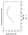
- FIG. 7 illustrates the T-wave amplitude fraction as a function of the blood glucose level also for levels in the range of 40 mg/dl to about 140 mg/dl.
- T-wave amplitude fraction increases with rising glucose levels in the range of 40 mg/dl to about 90 mg/dl, then decreasing with rising glucose levels in the range of 90 mg/dl to about 140 mg/dl.
- the overall trend of T-wave amplitude as a function of blood glucose level is somewhat nonlinear though it can be approximated by a first linear function below about 90 mg/dl and a second linear function above about 90 mg/dl.
- T-wave amplitude fraction appears to be ineffective by itself as a proxy for blood glucose levels since a single T-wave amplitude fraction value, such as 0.8 can correspond to at least two blood glucose level values.
- corrected T-wave amplitude fraction is employed in combination with at least one other cardiac signal feature that demonstrates a substantially monotonically-varying response as a function of blood glucose levels.
- monotonically-varying it is meant that the cardiac feature exhibits one and only one value for each value of the blood glucose level, at least within selected ranges of blood glucose values.
- QTc interval is a cardiac signal features.
- other cardiac signal features may be employed in the alternative such as heart rate variability, QT dispersion (i.e. the difference among QT intervals as measured by different leads), and QT equivalents such as RT or ST intervals.
- FIG. 8 illustrates predicted blood glucose levels as a function of actual blood glucose levels achieved by fitting the data from FIGS. 6 and 7 to a linear function, specifically the function of Eq. 1.
- the predicted glucose level closely matches the actual glucose level at each data point and confirms the suitability of using the linear relationship of Eq. 1.
- the data shown within FIGS. 6 - 7 is based on information provided within the aforementioned paper by Ireland, et al. The data should not be construed as necessarily representing specific data for any particular actual patient. Some degree variation is to be expected when applying the techniques of the invention to particular patients.
Landscapes
- Health & Medical Sciences (AREA)
- Life Sciences & Earth Sciences (AREA)
- Cardiology (AREA)
- Public Health (AREA)
- Veterinary Medicine (AREA)
- Biophysics (AREA)
- Physics & Mathematics (AREA)
- Engineering & Computer Science (AREA)
- Biomedical Technology (AREA)
- Heart & Thoracic Surgery (AREA)
- General Health & Medical Sciences (AREA)
- Animal Behavior & Ethology (AREA)
- Surgery (AREA)
- Molecular Biology (AREA)
- Medical Informatics (AREA)
- Pathology (AREA)
- Optics & Photonics (AREA)
- Physiology (AREA)
- Emergency Medicine (AREA)
- Nuclear Medicine, Radiotherapy & Molecular Imaging (AREA)
- Radiology & Medical Imaging (AREA)
- Electrotherapy Devices (AREA)
Claims (7)
- Dispositif médical implantable comprenant une unité de détection de signal cardiaque (82, 84) fonctionnelle pour détecter des ondes T et des intervalles QT, et un système de surveillance du glucose (101), fonctionnel pour déduire des taux de glycémie à partir d'une combinaison des ondes T détectées et des intervalles QT détectés, caractérisé en ce que le système de surveillance du glucose est en outre fonctionnel pour : convertir des ondes T détectées en fractions d'amplitude d'onde T, convertir des intervalles QT détectés en deltas QTc d'intervalles QT; et déterminer le taux de glycémie sur base d'une combinaison des fractions d'amplitude d'onde T et des deltas QTc.
- Dispositif selon la revendication 1, caractérisé par un moyen pour comparer le taux de glycémie à une limite supérieure, et un moyen pour générer un signal d'avertissement indiquant que le taux de glycémie est trop élevé si le taux de glycémie dépasse la limite supérieure.
- Dispositif selon la revendication 1, caractérisé par un moyen pour comparer le taux de glycémie à une limite inférieure, et un moyen pour générer un signal d'avertissement indiquant que le taux de glycémie est trop bas si le taux de glycémie devient inférieur à la limite inférieure.
- Dispositif selon une quelconque des revendications précédentes, caractérisé en ce qu'il comprend une pompe à insuline (103) et un moyen pour commander la pompe à insuline sur base du taux de glycémie.
- Dispositif selon une quelconque des revendications précédentes, caractérisé par un moyen pour commander les fonctions du dispositif implanté sur base du taux de glycémie.
- Dispositif selon une quelconque des revendications précédentes, caractérisé par un moyen pour enregistrer le taux de glycémie pour transmission subséquente à un dispositif extérieur (102).
- Dispositif selon une quelconque des revendications précédentes, caractérisé en ce que le système de surveillance du glucose (101) est monté dans un boîtier de dispositif (40) et l'unité de détection de signal cardiaque comprend un ou plusieurs de : au moins une bobine de défibrillation (36, 38) pour placement dans le ventricule d'un patient, et des circuits (84) pour détecter un signal de tension entre la bobine et le boîtier de dispositif; et une pluralité d'électrodes (44, 52, 54) pour installation en différents endroits dans le ventricule du patient, et des circuits pour moyenner des signaux de tension détectés séparément entre la pluralité d'électrodes et le boîtier de dispositif.
Applications Claiming Priority (4)
| Application Number | Priority Date | Filing Date | Title |
|---|---|---|---|
| US277467 | 1981-06-25 | ||
| US277468 | 2002-10-21 | ||
| US10/277,467 US7016720B2 (en) | 2002-10-21 | 2002-10-21 | System and method for monitoring blood glucose levels using an implantable medical device |
| US10/277,468 US7029443B2 (en) | 2002-10-21 | 2002-10-21 | System and method for monitoring blood glucose levels using an implantable medical device |
Publications (2)
| Publication Number | Publication Date |
|---|---|
| EP1419731A1 EP1419731A1 (fr) | 2004-05-19 |
| EP1419731B1 true EP1419731B1 (fr) | 2006-03-01 |
Family
ID=32179470
Family Applications (1)
| Application Number | Title | Priority Date | Filing Date |
|---|---|---|---|
| EP03256605A Expired - Lifetime EP1419731B1 (fr) | 2002-10-21 | 2003-10-20 | Système pour la surveillance du taux de glucose sanguin en utilisant un dispositif médical implantable |
Country Status (3)
| Country | Link |
|---|---|
| US (3) | US7029443B2 (fr) |
| EP (1) | EP1419731B1 (fr) |
| DE (1) | DE60303758T2 (fr) |
Cited By (15)
| Publication number | Priority date | Publication date | Assignee | Title |
|---|---|---|---|---|
| US7502644B2 (en) | 2005-01-25 | 2009-03-10 | Pacesetter, Inc. | System and method for distinguishing among cardiac ischemia, hypoglycemia and hyperglycemia using an implantable medical device |
| US7590443B2 (en) | 2005-04-27 | 2009-09-15 | Pacesetter, Inc | System and method for detecting hypoglycemia based on a paced depolarization integral using an implantable medical device |
| US7756572B1 (en) | 2005-01-25 | 2010-07-13 | Pacesetter, Inc. | System and method for efficiently distinguishing among cardiac ischemia, hypoglycemia and hyperglycemia using an implantable medical device and an external system |
| US8019410B1 (en) | 2007-08-22 | 2011-09-13 | Pacesetter, Inc. | System and method for detecting hypoglycemia using an implantable medical device based on pre-symptomatic physiological responses |
| US8185181B2 (en) | 2009-10-30 | 2012-05-22 | Abbott Diabetes Care Inc. | Method and apparatus for detecting false hypoglycemic conditions |
| US8216138B1 (en) | 2007-10-23 | 2012-07-10 | Abbott Diabetes Care Inc. | Correlation of alternative site blood and interstitial fluid glucose concentrations to venous glucose concentration |
| US8532935B2 (en) | 2009-01-29 | 2013-09-10 | Abbott Diabetes Care Inc. | Method and device for providing offset model based calibration for analyte sensor |
| US8583205B2 (en) | 2008-03-28 | 2013-11-12 | Abbott Diabetes Care Inc. | Analyte sensor calibration management |
| US8635046B2 (en) | 2010-06-23 | 2014-01-21 | Abbott Diabetes Care Inc. | Method and system for evaluating analyte sensor response characteristics |
| US8718958B2 (en) | 2006-10-26 | 2014-05-06 | Abbott Diabetes Care Inc. | Method, system and computer program product for real-time detection of sensitivity decline in analyte sensors |
| US8744547B2 (en) | 2008-09-30 | 2014-06-03 | Abbott Diabetes Care Inc. | Optimizing analyte sensor calibration |
| US9113828B2 (en) | 2006-10-25 | 2015-08-25 | Abbott Diabetes Care Inc. | Method and system for providing analyte monitoring |
| US9326709B2 (en) | 2010-03-10 | 2016-05-03 | Abbott Diabetes Care Inc. | Systems, devices and methods for managing glucose levels |
| US9326707B2 (en) | 2008-11-10 | 2016-05-03 | Abbott Diabetes Care Inc. | Alarm characterization for analyte monitoring devices and systems |
| US9474475B1 (en) | 2013-03-15 | 2016-10-25 | Abbott Diabetes Care Inc. | Multi-rate analyte sensor data collection with sample rate configurable signal processing |
Families Citing this family (109)
| Publication number | Priority date | Publication date | Assignee | Title |
|---|---|---|---|---|
| JP4498636B2 (ja) | 2001-04-27 | 2010-07-07 | 日本サーモスタット株式会社 | サーモスタット装置 |
| US7103412B1 (en) * | 2003-05-02 | 2006-09-05 | Pacesetter, Inc. | Implantable cardiac stimulation device and method for detecting asymptomatic diabetes |
| AU2003902187A0 (en) * | 2003-05-08 | 2003-05-22 | Aimedics Pty Ltd | Patient monitor |
| US20050027183A1 (en) * | 2003-07-01 | 2005-02-03 | Antonio Sastre | Method for non-invasive monitoring of blood and tissue glucose |
| US20190357827A1 (en) | 2003-08-01 | 2019-11-28 | Dexcom, Inc. | Analyte sensor |
| US20050033133A1 (en) * | 2003-08-06 | 2005-02-10 | Clifford Kraft | Implantable chip medical diagnostic device for bodily fluids |
| US8118741B2 (en) | 2004-12-20 | 2012-02-21 | Hypo-Safe A/X | Method and apparatus for prediction and warning of hypoglycaemic attack |
| US7794742B2 (en) * | 2005-02-08 | 2010-09-14 | University Of Washington | Devices for promoting epithelial cell differentiation and keratinization |
| US7904158B2 (en) * | 2005-04-28 | 2011-03-08 | Medtronic, Inc. | Measurement of coronary sinus parameters to optimize left ventricular performance |
| US8251904B2 (en) | 2005-06-09 | 2012-08-28 | Roche Diagnostics Operations, Inc. | Device and method for insulin dosing |
| US7529580B2 (en) * | 2005-08-11 | 2009-05-05 | Pacesetter, Inc. | Detection of renal failure by cardiac implantable medical device |
| US7400920B1 (en) | 2005-08-11 | 2008-07-15 | Pacesetter, Inc. | Detection of renal failure by cardiac implantable medical device |
| CA2620586A1 (fr) | 2005-08-31 | 2007-03-08 | Boris P. Kovatchev | Amelioration de la precision de capteurs de glucose en continu |
| US9675290B2 (en) | 2012-10-30 | 2017-06-13 | Abbott Diabetes Care Inc. | Sensitivity calibration of in vivo sensors used to measure analyte concentration |
| US9392969B2 (en) | 2008-08-31 | 2016-07-19 | Abbott Diabetes Care Inc. | Closed loop control and signal attenuation detection |
| US7672716B1 (en) | 2006-04-03 | 2010-03-02 | Pacesetter, Inc. | QT-based system and method for detecting and distinguishing dilated cardiomyopathy and heart failure using an implantable medical device |
| US7462150B1 (en) * | 2006-06-09 | 2008-12-09 | Pacesetter, Inc. | System and method for evaluating impaired glucose tolerance and diabetes mellitus within a patient using an implantable medical device |
| US8092386B1 (en) | 2006-12-22 | 2012-01-10 | Pacesetter, Inc. | Method and implantable system for blood-glucose concentration monitoring |
| US8934963B1 (en) | 2007-01-16 | 2015-01-13 | Pacesetter, Inc. | Method and apparatus for monitoring arrythmogenic effects of medications using an implantable device |
| US8265739B1 (en) | 2007-01-19 | 2012-09-11 | Pacesetter, Inc. | Systems and methods for distinguishing cardiac ischemia from systemic influences on IEGM morphology using an implantable medical device |
| US8417311B2 (en) | 2008-09-12 | 2013-04-09 | Optiscan Biomedical Corporation | Fluid component analysis system and method for glucose monitoring and control |
| US7769436B1 (en) | 2007-06-04 | 2010-08-03 | Pacesetter, Inc. | System and method for adaptively adjusting cardiac ischemia detection thresholds and other detection thresholds used by an implantable medical device |
| US7731658B2 (en) * | 2007-08-16 | 2010-06-08 | Cardiac Pacemakers, Inc. | Glycemic control monitoring using implantable medical device |
| US7813791B1 (en) | 2007-08-20 | 2010-10-12 | Pacesetter, Inc. | Systems and methods for employing an FFT to distinguish R-waves from T-waves using an implantable medical device |
| EP3868284A1 (fr) | 2007-10-10 | 2021-08-25 | Optiscan Biomedical Corporation | Système d'analyse de composant de fluide et procédé pour contrôler et réguler le glucose |
| US20090137890A1 (en) * | 2007-11-27 | 2009-05-28 | Burnes John E | Devices to monitor glucose levels and ischemia |
| US20090164239A1 (en) | 2007-12-19 | 2009-06-25 | Abbott Diabetes Care, Inc. | Dynamic Display Of Glucose Information |
| US7959598B2 (en) | 2008-08-20 | 2011-06-14 | Asante Solutions, Inc. | Infusion pump systems and methods |
| US20100057158A1 (en) * | 2008-08-26 | 2010-03-04 | Pacesetter, Inc. | Neurostimulation Based On Glycemic Condition |
| US9301698B2 (en) | 2008-10-31 | 2016-04-05 | Medtronic, Inc. | Method and apparatus to detect ischemia with a pressure sensor |
| US8280523B2 (en) | 2008-12-22 | 2012-10-02 | Pacesetter, Inc. | System and method for monitoring diastolic function using an implantable medical device |
| CA2747309C (fr) | 2008-12-23 | 2023-09-26 | F. Hoffmann-La Roche Ag | Procede de tests structures de diagnostic ou d'aide a la therapie pour un patient atteint d'une affection chronique, et dispositifs a cet effet |
| US10437962B2 (en) | 2008-12-23 | 2019-10-08 | Roche Diabetes Care Inc | Status reporting of a structured collection procedure |
| US20120011125A1 (en) | 2008-12-23 | 2012-01-12 | Roche Diagnostics Operations, Inc. | Management method and system for implementation, execution, data collection, and data analysis of a structured collection procedure which runs on a collection device |
| US9918635B2 (en) | 2008-12-23 | 2018-03-20 | Roche Diabetes Care, Inc. | Systems and methods for optimizing insulin dosage |
| US10456036B2 (en) | 2008-12-23 | 2019-10-29 | Roche Diabetes Care, Inc. | Structured tailoring |
| CA2750317C (fr) * | 2009-02-04 | 2016-10-25 | Sanofi-Aventis Deutschland Gmbh | Dispositif medical et procede de regulation de la glycemie |
| US8630692B2 (en) * | 2009-04-30 | 2014-01-14 | Pacesetter, Inc. | Method and implantable system for blood-glucose concentration monitoring using parallel methodologies |
| RU2012123025A (ru) * | 2009-11-04 | 2013-12-10 | Эймедикс Пти Лтд | Системы тревожной сигнализации, использующие контролируемые физиологические данные и способы разностных трендов |
| US20120277723A1 (en) * | 2009-11-04 | 2012-11-01 | Aimedics Pty Ltd | System and method for the integration of fused-data hypoglycaemia alarms into closed-loop glycaemic control systems |
| US10092229B2 (en) | 2010-06-29 | 2018-10-09 | Abbott Diabetes Care Inc. | Calibration of analyte measurement system |
| US20120173151A1 (en) | 2010-12-29 | 2012-07-05 | Roche Diagnostics Operations, Inc. | Methods of assessing diabetes treatment protocols based on protocol complexity levels and patient proficiency levels |
| US9848809B2 (en) | 2011-04-15 | 2017-12-26 | Dexcom, Inc. | Advanced analyte sensor calibration and error detection |
| US9158890B2 (en) | 2011-07-27 | 2015-10-13 | At&T Mobility Ii Llc | Mobile applications and methods for conveying performance information of a cardiac pacemaker |
| WO2013066849A1 (fr) | 2011-10-31 | 2013-05-10 | Abbott Diabetes Care Inc. | Mécanisme de prévention de fausse alarme de seuil de glucose à risque variable basé sur un modèle |
| CN102500013A (zh) * | 2011-11-22 | 2012-06-20 | 北京化工大学 | 基于模型预测控制的大剂量胰岛素全自动智能输注方法和装置 |
| US9433376B2 (en) | 2012-03-16 | 2016-09-06 | Dexcom, Inc. | Systems and methods for processing analyte sensor data |
| US20130332196A1 (en) * | 2012-06-07 | 2013-12-12 | The Government Of The United States As Represented By The Secretary Of The Army | Diabetes Monitoring Using Smart Device |
| EP2898470A4 (fr) * | 2012-09-21 | 2017-09-06 | CardioMems, Inc. | Procédé et système de prise en charge de patients sur la base de tendances |
| US9907492B2 (en) | 2012-09-26 | 2018-03-06 | Abbott Diabetes Care Inc. | Method and apparatus for improving lag correction during in vivo measurement of analyte concentration with analyte concentration variability and range data |
| EP2770452A1 (fr) * | 2013-02-22 | 2014-08-27 | Samsung Electronics Co., Ltd. | Procédé et système de transmission de résultat d'examen d'un échantillon de dispositif médical à la destination au moyen d'un dispositif mobile |
| US10404784B2 (en) * | 2013-02-22 | 2019-09-03 | Samsung Electronics Co., Ltd. | Method and system for transmitting result of examination of specimen from medical device to destination |
| US10433773B1 (en) | 2013-03-15 | 2019-10-08 | Abbott Diabetes Care Inc. | Noise rejection methods and apparatus for sparsely sampled analyte sensor data |
| US10076285B2 (en) | 2013-03-15 | 2018-09-18 | Abbott Diabetes Care Inc. | Sensor fault detection using analyte sensor data pattern comparison |
| US9561324B2 (en) | 2013-07-19 | 2017-02-07 | Bigfoot Biomedical, Inc. | Infusion pump system and method |
| GB2523989B (en) | 2014-01-30 | 2020-07-29 | Insulet Netherlands B V | Therapeutic product delivery system and method of pairing |
| WO2015153482A1 (fr) | 2014-03-30 | 2015-10-08 | Abbott Diabetes Care Inc. | Procédé et appareil permettant de déterminer le début du repas et le pic prandial dans des systèmes de surveillance d'analyte |
| US10737024B2 (en) | 2015-02-18 | 2020-08-11 | Insulet Corporation | Fluid delivery and infusion devices, and methods of use thereof |
| WO2017123525A1 (fr) | 2016-01-13 | 2017-07-20 | Bigfoot Biomedical, Inc. | Interface utilisateur pour système de gestion du diabète |
| US10780223B2 (en) | 2016-01-14 | 2020-09-22 | Bigfoot Biomedical, Inc. | Adjusting insulin delivery rates |
| US10610643B2 (en) | 2016-01-14 | 2020-04-07 | Bigfoot Biomedical, Inc. | Occlusion resolution in medication delivery devices, systems, and methods |
| US11657175B2 (en) * | 2016-02-23 | 2023-05-23 | Philips Medical Systems Technologies Ltd | Patient medical data acquisition system and method using an external device |
| US12383166B2 (en) | 2016-05-23 | 2025-08-12 | Insulet Corporation | Insulin delivery system and methods with risk-based set points |
| US10765807B2 (en) | 2016-09-23 | 2020-09-08 | Insulet Corporation | Fluid delivery device with sensor |
| US11096624B2 (en) | 2016-12-12 | 2021-08-24 | Bigfoot Biomedical, Inc. | Alarms and alerts for medication delivery devices and systems |
| US10758675B2 (en) | 2017-01-13 | 2020-09-01 | Bigfoot Biomedical, Inc. | System and method for adjusting insulin delivery |
| WO2018132765A1 (fr) | 2017-01-13 | 2018-07-19 | Mazlish Bryan | Procédés, systèmes et dispositifs d'administration d'insuline |
| EP3568862B1 (fr) | 2017-01-13 | 2026-03-18 | Insulet Corporation | Système et procédé d'ajustement d'administration d'insuline |
| US10500334B2 (en) | 2017-01-13 | 2019-12-10 | Bigfoot Biomedical, Inc. | System and method for adjusting insulin delivery |
| US10583250B2 (en) | 2017-01-13 | 2020-03-10 | Bigfoot Biomedical, Inc. | System and method for adjusting insulin delivery |
| EP3568860B1 (fr) | 2017-01-13 | 2025-12-10 | Insulet Corporation | Méthodes, systèmes et dispositifs d'administration d'insuline |
| EP3928687B1 (fr) | 2017-10-24 | 2024-06-26 | Dexcom, Inc. | Dispositif portable avec un capteur d'analyte préconnecté |
| US11331022B2 (en) | 2017-10-24 | 2022-05-17 | Dexcom, Inc. | Pre-connected analyte sensors |
| USD928199S1 (en) | 2018-04-02 | 2021-08-17 | Bigfoot Biomedical, Inc. | Medication delivery device with icons |
| CN118750687A (zh) | 2018-05-04 | 2024-10-11 | 英赛罗公司 | 基于控制算法的药物输送系统的安全约束 |
| US12562251B1 (en) | 2018-05-09 | 2026-02-24 | Bigfoot Biomedical, Inc. | Computing architecture for assuring the provenance of medication therapy related parameters, and related systems, methods and devices |
| JP2022501139A (ja) | 2018-09-28 | 2022-01-06 | インスレット コーポレイション | 人工膵臓システム用活動モード |
| US11565039B2 (en) | 2018-10-11 | 2023-01-31 | Insulet Corporation | Event detection for drug delivery system |
| USD920343S1 (en) | 2019-01-09 | 2021-05-25 | Bigfoot Biomedical, Inc. | Display screen or portion thereof with graphical user interface associated with insulin delivery |
| GB2586788A (en) * | 2019-08-30 | 2021-03-10 | Univ Warwick | Electrocardiogram-based blood glucose level monitoring |
| US11801344B2 (en) | 2019-09-13 | 2023-10-31 | Insulet Corporation | Blood glucose rate of change modulation of meal and correction insulin bolus quantity |
| US11935637B2 (en) | 2019-09-27 | 2024-03-19 | Insulet Corporation | Onboarding and total daily insulin adaptivity |
| US11957875B2 (en) | 2019-12-06 | 2024-04-16 | Insulet Corporation | Techniques and devices providing adaptivity and personalization in diabetes treatment |
| US11833329B2 (en) | 2019-12-20 | 2023-12-05 | Insulet Corporation | Techniques for improved automatic drug delivery performance using delivery tendencies from past delivery history and use patterns |
| JP7512395B2 (ja) | 2020-01-06 | 2024-07-08 | インスレット コーポレイション | 持続する残差に基づく食事および/または運動行為の予測 |
| EP4100958A1 (fr) | 2020-02-03 | 2022-12-14 | Insulet Corporation | Utilisation d'une logique floue pour prédire un comportement d'utilisateur affectant la glycémie |
| US11551802B2 (en) | 2020-02-11 | 2023-01-10 | Insulet Corporation | Early meal detection and calorie intake detection |
| US11986630B2 (en) | 2020-02-12 | 2024-05-21 | Insulet Corporation | Dual hormone delivery system for reducing impending hypoglycemia and/or hyperglycemia risk |
| US11547800B2 (en) | 2020-02-12 | 2023-01-10 | Insulet Corporation | User parameter dependent cost function for personalized reduction of hypoglycemia and/or hyperglycemia in a closed loop artificial pancreas system |
| US11324889B2 (en) | 2020-02-14 | 2022-05-10 | Insulet Corporation | Compensation for missing readings from a glucose monitor in an automated insulin delivery system |
| US12495994B2 (en) | 2020-02-20 | 2025-12-16 | Insulet Corporation | Meal bolus subcategories in model based insulin therapy |
| US11607493B2 (en) | 2020-04-06 | 2023-03-21 | Insulet Corporation | Initial total daily insulin setting for user onboarding |
| US12121700B2 (en) | 2020-07-22 | 2024-10-22 | Insulet Corporation | Open-loop insulin delivery basal parameters based on insulin delivery records |
| US11684716B2 (en) | 2020-07-31 | 2023-06-27 | Insulet Corporation | Techniques to reduce risk of occlusions in drug delivery systems |
| US12569619B2 (en) | 2020-09-21 | 2026-03-10 | Insulet Corporation | Techniques for determining automated insulin delivery dosages |
| EP4221588A1 (fr) | 2020-09-30 | 2023-08-09 | Insulet Corporation | Communications sans fil sécurisées entre un dispositif de surveillance de glucose et d'autres dispositifs |
| US12128215B2 (en) | 2020-09-30 | 2024-10-29 | Insulet Corporation | Drug delivery device with integrated optical-based glucose monitor |
| US11160925B1 (en) | 2021-01-29 | 2021-11-02 | Insulet Corporation | Automatic drug delivery system for delivery of a GLP-1 therapeutic |
| US12431229B2 (en) | 2021-03-10 | 2025-09-30 | Insulet Corporation | Medicament delivery device with an adjustable and piecewise analyte level cost component to address persistent positive analyte level excursions |
| US11904140B2 (en) | 2021-03-10 | 2024-02-20 | Insulet Corporation | Adaptable asymmetric medicament cost component in a control system for medicament delivery |
| US12592306B2 (en) | 2021-04-28 | 2026-03-31 | Insulet Corporation | Devices and methods for initialization of drug delivery devices using measured analyte sensor information |
| US12496398B2 (en) | 2021-05-28 | 2025-12-16 | Insulet Corporation | Threshold based automatic glucose control response |
| US12406760B2 (en) | 2021-06-07 | 2025-09-02 | Insulet Corporation | Exercise safety prediction based on physiological conditions |
| US12514980B2 (en) | 2021-06-30 | 2026-01-06 | Insulet Corporation | Adjustment of medicament delivery by a medicament delivery device based on menstrual cycle phase |
| US12521486B2 (en) | 2021-07-16 | 2026-01-13 | Insulet Corporation | Method for modification of insulin delivery during pregnancy in automatic insulin delivery systems |
| EP4409581A1 (fr) | 2021-09-27 | 2024-08-07 | Insulet Corporation | Techniques permettant l'adaptation de paramètres dans des systèmes d'aide par entrée d'utilisateur |
| US11439754B1 (en) | 2021-12-01 | 2022-09-13 | Insulet Corporation | Optimizing embedded formulations for drug delivery |
| EP4243030A1 (fr) | 2022-03-09 | 2023-09-13 | Insulet Corporation | Ajustement de paramètres d'administration de médicament dans un mode d'administration de médicament en boucle ouverte |
| CN120457493A (zh) | 2023-01-06 | 2025-08-08 | 英赛罗公司 | 自动或手动启动的随餐推注输送及随后的自动安全约束放宽 |
Family Cites Families (16)
| Publication number | Priority date | Publication date | Assignee | Title |
|---|---|---|---|---|
| US4731051A (en) | 1979-04-27 | 1988-03-15 | The Johns Hopkins University | Programmable control means for providing safe and controlled medication infusion |
| NL8105381A (nl) * | 1981-11-27 | 1983-06-16 | Tno | Werkwijze en inrichting voor het corrigeren van de manchetdruk bij het meten van de bloeddruk in een lichaamsdeel met behulp van een plethysmograaf. |
| US4704029A (en) * | 1985-12-26 | 1987-11-03 | Research Corporation | Blood glucose monitor |
| US4947845A (en) | 1989-01-13 | 1990-08-14 | Pacesetter Infusion, Ltd. | Method of maximizing catheter longevity in an implantable medication infusion system |
| US5437285A (en) * | 1991-02-20 | 1995-08-01 | Georgetown University | Method and apparatus for prediction of sudden cardiac death by simultaneous assessment of autonomic function and cardiac electrical stability |
| US5272379A (en) * | 1991-09-26 | 1993-12-21 | Mitsubishi Denki K.K. | Power supply device for an electric vehicle |
| US5419338A (en) * | 1994-02-22 | 1995-05-30 | City Of Hope | Autonomic nervous system testing by bi-variate spectral analysis of heart period and QT interval variability |
| US5741211A (en) | 1995-10-26 | 1998-04-21 | Medtronic, Inc. | System and method for continuous monitoring of diabetes-related blood constituents |
| US5919216A (en) | 1997-06-16 | 1999-07-06 | Medtronic, Inc. | System and method for enhancement of glucose production by stimulation of pancreatic beta cells |
| US6353226B1 (en) * | 1998-11-23 | 2002-03-05 | Abbott Laboratories | Non-invasive sensor capable of determining optical parameters in a sample having multiple layers |
| US6272379B1 (en) | 1999-03-17 | 2001-08-07 | Cathco, Inc. | Implantable electronic system with acute myocardial infarction detection and patient warning capabilities |
| US6923763B1 (en) * | 1999-08-23 | 2005-08-02 | University Of Virginia Patent Foundation | Method and apparatus for predicting the risk of hypoglycemia |
| US20020026141A1 (en) | 1999-11-04 | 2002-02-28 | Medtronic, Inc. | System for pancreatic stimulation and glucose measurement |
| US6572542B1 (en) * | 2000-03-03 | 2003-06-03 | Medtronic, Inc. | System and method for monitoring and controlling the glycemic state of a patient |
| AUPR343401A0 (en) * | 2001-02-28 | 2001-03-29 | Nguyen, Hung | Modelling and design for early warning systems using physiological responses |
| US7069078B2 (en) | 2002-04-22 | 2006-06-27 | Medtronic, Inc. | Insulin-mediated glucose uptake monitor |
-
2002
- 2002-10-21 US US10/277,468 patent/US7029443B2/en not_active Expired - Lifetime
- 2002-10-21 US US10/277,467 patent/US7016720B2/en not_active Expired - Lifetime
-
2003
- 2003-10-20 EP EP03256605A patent/EP1419731B1/fr not_active Expired - Lifetime
- 2003-10-20 DE DE60303758T patent/DE60303758T2/de not_active Expired - Lifetime
-
2005
- 2005-12-20 US US11/314,035 patent/US7680529B2/en not_active Expired - Lifetime
Cited By (18)
| Publication number | Priority date | Publication date | Assignee | Title |
|---|---|---|---|---|
| US7524287B2 (en) | 2005-01-25 | 2009-04-28 | Pacesetter, Inc. | System and method for distinguishing between hypoglycemia and hyperglycemia using an implantable medical device |
| US7756572B1 (en) | 2005-01-25 | 2010-07-13 | Pacesetter, Inc. | System and method for efficiently distinguishing among cardiac ischemia, hypoglycemia and hyperglycemia using an implantable medical device and an external system |
| US8180441B2 (en) | 2005-01-25 | 2012-05-15 | Pacesetter, Inc. | System and method for distinguishing among cardiac ischemia, hypoglycemia and hyperglycemia using an implantable medical device |
| US7502644B2 (en) | 2005-01-25 | 2009-03-10 | Pacesetter, Inc. | System and method for distinguishing among cardiac ischemia, hypoglycemia and hyperglycemia using an implantable medical device |
| US7590443B2 (en) | 2005-04-27 | 2009-09-15 | Pacesetter, Inc | System and method for detecting hypoglycemia based on a paced depolarization integral using an implantable medical device |
| US9113828B2 (en) | 2006-10-25 | 2015-08-25 | Abbott Diabetes Care Inc. | Method and system for providing analyte monitoring |
| US8718958B2 (en) | 2006-10-26 | 2014-05-06 | Abbott Diabetes Care Inc. | Method, system and computer program product for real-time detection of sensitivity decline in analyte sensors |
| US8019410B1 (en) | 2007-08-22 | 2011-09-13 | Pacesetter, Inc. | System and method for detecting hypoglycemia using an implantable medical device based on pre-symptomatic physiological responses |
| US8216138B1 (en) | 2007-10-23 | 2012-07-10 | Abbott Diabetes Care Inc. | Correlation of alternative site blood and interstitial fluid glucose concentrations to venous glucose concentration |
| US8583205B2 (en) | 2008-03-28 | 2013-11-12 | Abbott Diabetes Care Inc. | Analyte sensor calibration management |
| US8744547B2 (en) | 2008-09-30 | 2014-06-03 | Abbott Diabetes Care Inc. | Optimizing analyte sensor calibration |
| US9326707B2 (en) | 2008-11-10 | 2016-05-03 | Abbott Diabetes Care Inc. | Alarm characterization for analyte monitoring devices and systems |
| US8532935B2 (en) | 2009-01-29 | 2013-09-10 | Abbott Diabetes Care Inc. | Method and device for providing offset model based calibration for analyte sensor |
| US9050041B2 (en) | 2009-10-30 | 2015-06-09 | Abbott Diabetes Care Inc. | Method and apparatus for detecting false hypoglycemic conditions |
| US8185181B2 (en) | 2009-10-30 | 2012-05-22 | Abbott Diabetes Care Inc. | Method and apparatus for detecting false hypoglycemic conditions |
| US9326709B2 (en) | 2010-03-10 | 2016-05-03 | Abbott Diabetes Care Inc. | Systems, devices and methods for managing glucose levels |
| US8635046B2 (en) | 2010-06-23 | 2014-01-21 | Abbott Diabetes Care Inc. | Method and system for evaluating analyte sensor response characteristics |
| US9474475B1 (en) | 2013-03-15 | 2016-10-25 | Abbott Diabetes Care Inc. | Multi-rate analyte sensor data collection with sample rate configurable signal processing |
Also Published As
| Publication number | Publication date |
|---|---|
| US7016720B2 (en) | 2006-03-21 |
| US20060100494A1 (en) | 2006-05-11 |
| US7680529B2 (en) | 2010-03-16 |
| DE60303758D1 (de) | 2006-04-27 |
| US7029443B2 (en) | 2006-04-18 |
| US20040078065A1 (en) | 2004-04-22 |
| DE60303758T2 (de) | 2006-08-31 |
| EP1419731A1 (fr) | 2004-05-19 |
| US20040077962A1 (en) | 2004-04-22 |
Similar Documents
| Publication | Publication Date | Title |
|---|---|---|
| US7680529B2 (en) | System and method for monitoring blood glucose levels using an implantable medical device | |
| EP1629863B1 (fr) | Système et méthode permettant de déterminer une valeur optimale du délai atrioventriculaire à partir des délais de conduction intrinsèques. | |
| US8934963B1 (en) | Method and apparatus for monitoring arrythmogenic effects of medications using an implantable device | |
| US6922587B2 (en) | System and method for tracking progression of left ventricular dysfunction using implantable cardiac stimulation device | |
| EP1491234B1 (fr) | Appareil de surveillance de l'effet des médicaments sur les signaux cardiaques électriques grâce à l'utilisation d'un appareil implantable de stimulation cardiaque | |
| US6572557B2 (en) | System and method for monitoring progression of cardiac disease state using physiologic sensors | |
| US7103412B1 (en) | Implantable cardiac stimulation device and method for detecting asymptomatic diabetes | |
| US6993379B1 (en) | System and method for emulating a surface EKG using an implantable cardiac stimulation device | |
| US8265755B2 (en) | Systems and methods for optimizing ventricular pacing delays for use with multi-pole leads | |
| US6904313B1 (en) | Methods and systems for monitoring heart rate recovery | |
| EP1547648A1 (fr) | Système et procédé pour la determination d'un site optimal de la stimulation basée sur le temps d'activation du myocarde | |
| US20040102814A1 (en) | Physician programmer system with telemetered sensor waveform | |
| US8295918B2 (en) | Systems and methods for activating and controlling impedance-based detection systems of implantable medical devices | |
| US8380303B2 (en) | Systems and methods for activating and controlling impedance-based detection systems of implantable medical devices | |
| US20110106200A1 (en) | Stroke risk monitoring system including implantable medical device | |
| US20110208261A1 (en) | Systems and methods for assessing and reprogramming sensing vectors for use with an implantable cardiac rhythm management device | |
| US20120136406A1 (en) | Systems and Methods for Determining Optimal Atrioventricular Pacing Delays Based on Cardiomechanical Delays | |
| US6813514B1 (en) | System and method for emulating a surface EKG using an implantable cardiac stimulation device | |
| US20150142072A1 (en) | Systems and methods for determining optimal interventricular pacing delays based on electromechanical delays | |
| US6980850B1 (en) | System and method for emulating a surface EKG using an implantable cardiac stimulation device | |
| US7778699B1 (en) | System and method for trigger-specific recording of cardiac signals using an implantable medical device | |
| US6907287B1 (en) | Detecting and displaying diagnostic information pertaining to dynamic atrial overdrive pacing | |
| US7844333B1 (en) | Pacing therapy for transient ischemia treatment | |
| US8204592B1 (en) | System and method for generating and using cardiac ischemia diagnostics based on arrhythmia precursors and arrhythmia episodes | |
| US7505813B1 (en) | System and method for determining preferred atrioventricular pacing delay values based on intracardiac electrogram signals |
Legal Events
| Date | Code | Title | Description |
|---|---|---|---|
| PUAI | Public reference made under article 153(3) epc to a published international application that has entered the european phase |
Free format text: ORIGINAL CODE: 0009012 |
|
| AK | Designated contracting states |
Kind code of ref document: A1 Designated state(s): AT BE BG CH CY CZ DE DK EE ES FI FR GB GR HU IE IT LI LU MC NL PT RO SE SI SK TR |
|
| AX | Request for extension of the european patent |
Extension state: AL LT LV MK |
|
| 17P | Request for examination filed |
Effective date: 20041119 |
|
| AKX | Designation fees paid |
Designated state(s): CH DE FR IE IT LI |
|
| GRAP | Despatch of communication of intention to grant a patent |
Free format text: ORIGINAL CODE: EPIDOSNIGR1 |
|
| RTI1 | Title (correction) |
Free format text: SYSTEM FOR MONITORING BLOOD GLUCOSE LEVELS USING AN IMPLANTABLE MEDICAL DEVICE |
|
| GRAS | Grant fee paid |
Free format text: ORIGINAL CODE: EPIDOSNIGR3 |
|
| GRAA | (expected) grant |
Free format text: ORIGINAL CODE: 0009210 |
|
| AK | Designated contracting states |
Kind code of ref document: B1 Designated state(s): CH DE FR IE IT LI |
|
| PG25 | Lapsed in a contracting state [announced via postgrant information from national office to epo] |
Ref country code: IT Free format text: LAPSE BECAUSE OF FAILURE TO SUBMIT A TRANSLATION OF THE DESCRIPTION OR TO PAY THE FEE WITHIN THE PRESCRIBED TIME-LIMIT;WARNING: LAPSES OF ITALIAN PATENTS WITH EFFECTIVE DATE BEFORE 2007 MAY HAVE OCCURRED AT ANY TIME BEFORE 2007. THE CORRECT EFFECTIVE DATE MAY BE DIFFERENT FROM THE ONE RECORDED. Effective date: 20060301 |
|
| REG | Reference to a national code |
Ref country code: CH Ref legal event code: EP |
|
| REG | Reference to a national code |
Ref country code: IE Ref legal event code: FG4D |
|
| REF | Corresponds to: |
Ref document number: 60303758 Country of ref document: DE Date of ref document: 20060427 Kind code of ref document: P |
|
| REG | Reference to a national code |
Ref country code: DE Ref legal event code: R096 Ref document number: 60303758 Country of ref document: DE Effective date: 20060427 |
|
| REG | Reference to a national code |
Ref country code: CH Ref legal event code: NV Representative=s name: KIRKER & CIE SA |
|
| ET | Fr: translation filed | ||
| PGFP | Annual fee paid to national office [announced via postgrant information from national office to epo] |
Ref country code: IE Payment date: 20061026 Year of fee payment: 4 |
|
| PLBE | No opposition filed within time limit |
Free format text: ORIGINAL CODE: 0009261 |
|
| STAA | Information on the status of an ep patent application or granted ep patent |
Free format text: STATUS: NO OPPOSITION FILED WITHIN TIME LIMIT |
|
| 26N | No opposition filed |
Effective date: 20061204 |
|
| REG | Reference to a national code |
Ref country code: DE Ref legal event code: R097 Ref document number: 60303758 Country of ref document: DE Effective date: 20061204 |
|
| PG25 | Lapsed in a contracting state [announced via postgrant information from national office to epo] |
Ref country code: IE Free format text: LAPSE BECAUSE OF NON-PAYMENT OF DUE FEES Effective date: 20071022 |
|
| PGFP | Annual fee paid to national office [announced via postgrant information from national office to epo] |
Ref country code: CH Payment date: 20141127 Year of fee payment: 12 |
|
| PGFP | Annual fee paid to national office [announced via postgrant information from national office to epo] |
Ref country code: IT Payment date: 20141127 Year of fee payment: 12 |
|
| REG | Reference to a national code |
Ref country code: FR Ref legal event code: PLFP Year of fee payment: 13 |
|
| REG | Reference to a national code |
Ref country code: CH Ref legal event code: PL |
|
| PG25 | Lapsed in a contracting state [announced via postgrant information from national office to epo] |
Ref country code: IT Free format text: LAPSE BECAUSE OF NON-PAYMENT OF DUE FEES Effective date: 20151020 Ref country code: CH Free format text: LAPSE BECAUSE OF NON-PAYMENT OF DUE FEES Effective date: 20151031 Ref country code: LI Free format text: LAPSE BECAUSE OF NON-PAYMENT OF DUE FEES Effective date: 20151031 |
|
| REG | Reference to a national code |
Ref country code: FR Ref legal event code: PLFP Year of fee payment: 14 |
|
| REG | Reference to a national code |
Ref country code: FR Ref legal event code: PLFP Year of fee payment: 15 |
|
| REG | Reference to a national code |
Ref country code: FR Ref legal event code: PLFP Year of fee payment: 16 |
|
| PGFP | Annual fee paid to national office [announced via postgrant information from national office to epo] |
Ref country code: FR Payment date: 20190924 Year of fee payment: 17 |
|
| PGFP | Annual fee paid to national office [announced via postgrant information from national office to epo] |
Ref country code: DE Payment date: 20190917 Year of fee payment: 17 |
|
| REG | Reference to a national code |
Ref country code: DE Ref legal event code: R119 Ref document number: 60303758 Country of ref document: DE |
|
| PG25 | Lapsed in a contracting state [announced via postgrant information from national office to epo] |
Ref country code: DE Free format text: LAPSE BECAUSE OF NON-PAYMENT OF DUE FEES Effective date: 20210501 Ref country code: FR Free format text: LAPSE BECAUSE OF NON-PAYMENT OF DUE FEES Effective date: 20201031 |
|
| P01 | Opt-out of the competence of the unified patent court (upc) registered |
Effective date: 20230623 |