EP1419826A2 - Verfahren und Vorrichtung zum Abgeben von Fluid sowie Patrone - Google Patents
Verfahren und Vorrichtung zum Abgeben von Fluid sowie Patrone Download PDFInfo
- Publication number
- EP1419826A2 EP1419826A2 EP03025921A EP03025921A EP1419826A2 EP 1419826 A2 EP1419826 A2 EP 1419826A2 EP 03025921 A EP03025921 A EP 03025921A EP 03025921 A EP03025921 A EP 03025921A EP 1419826 A2 EP1419826 A2 EP 1419826A2
- Authority
- EP
- European Patent Office
- Prior art keywords
- fluid
- heat transfer
- permeable structure
- transfer chamber
- cartridge
- Prior art date
- Legal status (The legal status is an assumption and is not a legal conclusion. Google has not performed a legal analysis and makes no representation as to the accuracy of the status listed.)
- Withdrawn
Links
Images


Classifications
-
- H—ELECTRICITY
- H05—ELECTRIC TECHNIQUES NOT OTHERWISE PROVIDED FOR
- H05B—ELECTRIC HEATING; ELECTRIC LIGHT SOURCES NOT OTHERWISE PROVIDED FOR; CIRCUIT ARRANGEMENTS FOR ELECTRIC LIGHT SOURCES, IN GENERAL
- H05B3/00—Ohmic-resistance heating
- H05B3/40—Heating elements having the shape of rods or tubes
- H05B3/42—Heating elements having the shape of rods or tubes non-flexible
-
- B—PERFORMING OPERATIONS; TRANSPORTING
- B05—SPRAYING OR ATOMISING IN GENERAL; APPLYING FLUENT MATERIALS TO SURFACES, IN GENERAL
- B05C—APPARATUS FOR APPLYING FLUENT MATERIALS TO SURFACES, IN GENERAL
- B05C5/00—Apparatus in which liquid or other fluent material is projected, poured or allowed to flow on to the surface of the work
- B05C5/001—Apparatus in which liquid or other fluent material is projected, poured or allowed to flow on to the surface of the work incorporating means for heating or cooling the liquid or other fluent material
-
- B—PERFORMING OPERATIONS; TRANSPORTING
- B05—SPRAYING OR ATOMISING IN GENERAL; APPLYING FLUENT MATERIALS TO SURFACES, IN GENERAL
- B05C—APPARATUS FOR APPLYING FLUENT MATERIALS TO SURFACES, IN GENERAL
- B05C5/00—Apparatus in which liquid or other fluent material is projected, poured or allowed to flow on to the surface of the work
- B05C5/02—Apparatus in which liquid or other fluent material is projected, poured or allowed to flow on to the surface of the work the liquid or other fluent material being discharged through an outlet orifice by pressure, e.g. from an outlet device in contact or almost in contact, with the work
- B05C5/027—Coating heads with several outlets, e.g. aligned transversally to the moving direction of a web to be coated
-
- H—ELECTRICITY
- H05—ELECTRIC TECHNIQUES NOT OTHERWISE PROVIDED FOR
- H05B—ELECTRIC HEATING; ELECTRIC LIGHT SOURCES NOT OTHERWISE PROVIDED FOR; CIRCUIT ARRANGEMENTS FOR ELECTRIC LIGHT SOURCES, IN GENERAL
- H05B2203/00—Aspects relating to Ohmic resistive heating covered by group H05B3/00
- H05B2203/021—Heaters specially adapted for heating liquids
Definitions
- the invention relates to a method for dispensing a fluid, in which the fluid from a fluid source of a device for dispensing the Fluids supplied and through one assigned to the dispensing device Exit opening is released.
- the invention relates to a device for dispensing fluid, with a connectable to a fluid source and into a dispensing opening for dispensing the fluid flow channel.
- Flowable materials are used in many industrial applications (Fluids) dispensed and applied using fluid dispensers Deposited or applied substrates.
- the flowable materials can be, for example, adhesives, varnishes, sealing materials and for the substrates around hygiene articles, plastic films, furniture or Act machine parts or the like.
- the delivery of the flowable Depending on the application, materials can, for example, be strip or foil-shaped, or the material is optionally sprayed with the help of a gas jet influencing the fluid.
- the fluid dispensers are to a fluid source, for example an adhesive container is connected and the fluid is removed using a Pump with the interposition of so-called order valves for example a circular or slot-shaped outlet opening promoted.
- the fluid before Levy is heated.
- a to heat gas acting on the fluid to be dispensed a base body of the dispenser to be electrically heated, so that formed in the base body Liquid flowing through flow channels or gas flowing therethrough is heated by the Flow channel limiting inner wall to a Heat transfer comes through convection.
- a gas in a fluid dispenser it is known to be a zigzag training flow channel for the gas.
- the zigzag Design serves the purpose that for a Heat transfer available flow path too extend and thereby improve the heat transfer.
- the disadvantage of this is that the design effort for one Production of such a flow course is very complex and is therefore expensive.
- the object of the present invention is a method and a Specify the device of the type mentioned and a cartridge, with which the heat transfer is improved.
- the invention solves the problem with an input method mentioned type in that the fluid prior to delivery by the Outlet opening for heating or cooling by a Heat transfer chamber flows in which a fluid-permeable, structure having a plurality of communicating cavities is formed, which is flowed around by the fluid.
- the invention also achieves the object in an input device mentioned type by a heat transfer chamber for heating or cooling the fluid in which a fluid permeable, a Large number of communicating cavities structure is trained.
- the advantages of the method and the Device according to the invention consist in that the Heat transfer for heating or alternatively for cooling a liquid and / or a gas prior to delivery from the Dispensing device can be significantly improved by the Provision of the fluid-permeable structure according to the invention, the is flowed around by the fluid.
- the fluid permeable structure is preferably a sintered material, particularly preferably a Sintered metal, which is essentially rigid and a variety of interconnected cavities through which the fluid can flow through.
- the heat transfer is due to the fluid permeable, in the flow channel of the heat transfer chamber lying structure improved that the for Relevant surface heat transfer between the structure and the fluid to be heated and possibly also cooled is significantly enlarged, reproduced.
- the structure is closer to below described way heated so that heat is given off to the fluid can be over the large surface of the structure. Furthermore the heat transfer is improved in that the fluid during the flow through the structure is deflected in many ways and thereby a certain amount of turbulence arises, which improves the Ensures heat transfer.
- Heat transfer such as heating a liquid or a Gases improved significantly and the device can be relative be built compact. Especially when heating Pressurized gas for dispensing devices for spraying liquids they are like hot melt adhesive due to the fluid permeability Structure enlarged compared to a free flow channel Flow resistances negligible.
- the preferred sintered metal has the advantage that it is a large inner Has heat transfer surface, is dimensionally stable, easy manufacture and process and thus to the respective applications can be adjusted.
- others can also be used according to the invention open-pore, preferably essentially rigid structures such as Fabrics, metal mesh or rigid, open-cell foams be used.
- the fluid can advantageously flow through the Heat transfer chamber heated or cooled and at the same time be filtered through the fluid permeable structure, so that in addition for heating a cleaning of a gas or a liquid is made.
- the fluid-permeable structure is preferably in contact with the fluid inner surface of the heat transfer chamber. This takes one efficient heat transfer instead.
- the fluid is a liquid, is in particular a flowable plastic such as hot melt adhesive and by flowing through the heat transfer chamber is heated. It is equally preferred that the fluid is a gas, is preferably air and by flowing through it Heat transfer chamber is heated, resulting in spray applications is advantageous.
- the device according to the invention is thereby constructive simply trained that the heat transfer chamber is formed by a section of the flow channel in which the fluid permeable structure is used.
- the heat transfer chamber is formed by a section of the flow channel in which the fluid permeable structure is used.
- the fluid-permeable structure in the is essentially designed as a cylindrical body which in a essential cylindrical bore is used because such a simple Production and assembly and also replacement of the fluid-permeable Structure is possible.
- the fluid-permeable Structure is a mechanically refurbished sintered metal part, preferably a turned sintered metal part.
- a mechanical Machining such as turning one with the heat transfer chamber in Contact surface of the sintered metal part Heat transfer between the sintered metal part and Heat transfer chamber further improved.
- By turning the outer pores are partially closed and a larger one Made contact area without the internal flow of fluid Structure is adversely affected.
- the heat transfer chamber is expediently in one Metal formed housing and are in the housing Heating means arranged for heating the housing.
- the fluid-permeable structure is part a cartridge that can be inserted into the device is designed to be detachable can be attached to the device and the fluid flows through it. This allows an exchange to be carried out quickly and easily become.
- the cartridge expediently has at least one Heating element on.
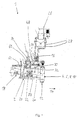
- the device 1 shown in Figures 1-3 which also as Application head or fluid delivery device is used for Dispensing and applying liquids such as adhesives, Hot melt adhesive, cold glue, sealants or the like on various Substrates.
- the device 1 comprises a metallic base body 2 and four delivery or order modules 4, 6, 8, 10, each with are screwed to the base body 2 and each of them by at least one outlet opening 12 the fluid is dispensed.
- the Order modules 4-10 can also be supplied with compressed gas Area of the outlet openings 12 exits and on through compressed gas nozzles the fluid released acts in such a way that it sprays or swirls becomes.
- the substrate to be coated is below the Outlet openings by means of conveyors, not shown, on the Device 1 guided past, for example in the direction of arrow 14.
- the device 1 can be attached to the base body 2 Fastening screws 16 are attached to support structures.
- a hose connector 18 is used to produce a Connection of the device 1 to a fluid source, not shown, such as an adhesive container for liquid adhesive.
- the adhesive is one of several Composed flow channel through the sections Base body 2 in the order modules 4-10 passed to the Outlet openings 12.
- the adhesive flow channel has a first Bore 20, which is only schematic by the dashed line is shown, a transverse distribution channel 22, with this communicating, leading to the respective modules 4-10 Oblique bores 24 and others within the order modules 4-10 trained channels that open into the outlet opening 12.
- Valve arrangement shown in detail, which a pneumatically movable from an open to a closed position Has valve body which cooperates with a valve seat.
- Actuation of the valve arrangement serves an electrically controllable Solenoid valve 26 and control air lines 28 connected to it and in the base body 2 formed compressed gas channels, which only are indicated by the dashed lines 30, 32 and for introduction serve from compressed gas in the order modules 4-10.
- compressed gas is on the Base body 2 an air connector 34 is mounted.
- the compressed gas flows through several compressed gas channels described in more detail below and serves to spray or swirl the by the Outlet opening 12 dispensed fluid.
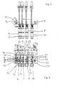
- the Base body 2 To heat the spray gas, preferably air, are within the Base body 2 several heat transfer chambers 36, 38, 40, 42, 44, 46 formed, through which the gas flows in the direction the arrows.
- two are in series switched preheat heat transfer chambers 36, 38 and four further and parallel, one each Order module 4-10 associated heat transfer chambers 40-46 intended.
- the Heat transfer chambers 36-46 are in one plane upper section of the base body and parallel to each other arranged.
- the base body 2 is made of composed of several housing sections, which means Screw connections are attached to each other.
- everyone Housing section takes at least one heat transfer chamber and is used to attach one order module 4-10 at a time.
- each heat transfer chamber 36-46 is a fluid permeable, structure having a plurality of communicating cavities formed in the embodiment by cylindrical Sintered metal parts 48 is formed.
- the heat transfer chamber with the Fluid-permeable structures arranged therein serve primarily for Improvement of heat transfer, in the embodiment of the Heating of the fluid permeable structure flowing gas.
- the sintered sintered metal parts are in the essentially rigid and can for example be made of a bronze-copper alloy consist.
- the fluid permeable structure but also as a metal mesh, metal mesh or an open-pore rigid foam material, through which gas or Liquid can flow through.
- the sintered metal parts 48 are each cylindrical in shape and in each cylindrical bores 50 formed in the base body 2 used and fitted. The heat supply or removal is below explained in more detail.
- Each hole 50 is a through hole in the Base body 2, more precisely the housing sections formed.
- the sintered metal parts 48 are well recognizable from those in FIG. 3 Inlet ends 52 of the bores 50 insertable. Both the entrants 52 and the opposite ends 54 of the bores 50 provided with an internal thread and are in a manner not shown gas-tight in the operating state with screw-in sealing plugs locked.
- the gas introduced through the inlet port 34 flows through the heat transfer chamber 36, then through a Cross bore 56 in the heat transfer chamber 38, then through a Cross bore 58 in the heat transfer chamber 40 in the Order module 4.
- coolants could be used to cool the Base body 2 and thus to reduce the temperature of the Heat transfer chambers 36-46 and the fluid permeable structure be provided, for example by inserting into the bores 58, 60 Coolant, for example a cooled gas or a liquid Coolant is introduced.
- Figure 4 shows a sectional view of an alternative Embodiment of a device 1, which is substantially similar is designed like the one previously described with reference to FIGS. 1-3 Contraption. The following are the differences from that in Figure 1-3 described device 1 is explained and otherwise Full reference to the above descriptions.
- the in Figure 4 basic body 2 takes three, not shown Order modules on which three heat transfer chambers 42, 44, 46 are assigned and can be attached in the same way, as shown with reference to Figure 3.
- Housing section 64 are two connected in series Heat transfer chambers 36, 38 formed.
- the fluid permeable Structures in the form of sintered metal parts 50 are also shown in FIG cylindrical bores 48 used.
- inlet ends 52 provided by plugs, not shown can be closed.
- the introduction of to be warmed Gas occurs through the inlet opening 66. Through cross bores 56, 58, 60 and 62 the gas can continue to the downstream Flow heat transfer chambers 42-48.
- Figure 5 shows an alternative embodiment of a Device according to the invention for dispensing fluid, in which a Liquid such as hot melt adhesive using a Heat transfer chamber 68 and one formed therein fluid permeable structure is heated or cooled.
- the fluid permeable structure is preferred, as detailed above is designed as a sintered metal part 70 in a cylindrical shape, which in a cylindrical formed in a base body 2 Bore 72 is inserted so that contact between the Sintered metal part 40 and the inner surface of the bore 72.
- the base body 2 in a manner not shown in Figure 5 with the help heated by heating means, preferably electrical heating elements or be cooled with the help of coolants, so that in the Heat transfer chamber 68 also using the sintered metal part 70 heating of the fluid-permeable structure Adhesive or cooling occurs while the adhesive is in Direction of arrows 74 from one by means of a connecting piece 18 connected fluid source through the heat transfer chamber 68 and through a downstream bore 76 to at least one Order module 4 flows, which has an outlet opening 12 for dispensing of the fluid.
- heating means preferably electrical heating elements or be cooled with the help of coolants
- Figure 6 illustrates a fluid permeable according to the invention Structure in the form of a cylindrical sintered metal part, which in one Flow channel for dispensing by means of a dispensing device 1
- Liquid or a gas can be used and for heat transfer, is preferably used for heating.
- the sintered metal part 48 can be mechanically attached to it after sintering machined outer cylinder surface, preferably turned be so that partially the pores on the lateral surface be closed due to deformation, causing a enlarged contact area is formed, which is in contact with the Inner wall of a hole is in which the sintered metal part 48th is used. This further improves the heat transfer.
- several separate ones can be used in a manner not shown Sections of sintered metal parts in a row in a row Heat transfer chamber to be placed.
- FIG. 7 shows a cartridge 71 according to the invention which is provided for this into a fluid delivery device 1, for example a device according to the descriptions above.
- the bullet 71 can be releasably attached to a heat transfer chamber 36-46 , for example with the help of sealing plugs, Bayonet locks, screw connections or the like.
- the cartridge 71 has an outer heating element 72 in the form of a hollow cylinder.
- the Heater 72 is provided with a variety of electrical conductors (not shown), which flows through the flow of an electric current Generate heat. For this purpose, electrical connections (not shown) available.
- the heating element 72 Inside the heating element 72 is the one according to the invention Fluid permeable structure in the form of a cylindrical body 74 formed, preferably as a sintered metal part, which in the inner Cavity of the hollow cylinder is fitted.
- the Cartridge 71 flows through one in the manner described above heating liquid, for example hot melt adhesive or a Gas to be heated, for example compressed air, the fluid-permeable Structure of the body 74 so that heating takes place.
- Cartridge 71 differs from that previously 7 described cartridge in that no Heating element is provided, but instead a housing in the form a tube 73 is provided, which is designed as a sintered metal part fluid permeable structure.
- the tube 73 is off, for example Made of aluminum or another good heat-conducting material.
- Grooves 76 formed in the sealing rings not shown, For example, O-rings can be inserted around one in a base body 2 formed bore Heat transfer chamber is sealed, so that too Heating fluid defined by the sintered metal part 74 fluid permeable structure flows.
- the alternative cartridge 78 shown in FIG. 9 has a center arranged electric heating element 80 and one as a hollow cylinder 82 trained fluid-permeable structure in the form of a sintered metal part on, in the inner cavity of the heating element 80 is firmly fitted.
- the cartridge 78 is equally in one Base body of a fluid delivery device 1 placed and detachable attached and the sintered metal part 80 is flowed around by fluid, so that heating takes place.
- the hot melt adhesive is in the heat transfer chamber 68 is heated and into the application module 4 initiated.
- liquid flows through the Connection piece 18 in the base body 2 and the modules 4-10 to be discharged from the outlet opening 12.
- the inner Wall of the heat transfer chambers 36-46 and the fluid permeable structure heated by means of heating means or in the case cooling with the help of coolants heated by means of heating means or in the case cooling with the help of coolants. That warmed up or cooled gas then continues to flow through the base body 2 in the Order modules 4-10 and is then heated to the the liquid to be dispensed acts as a spray, a swirl or the like.
Landscapes
- Coating Apparatus (AREA)
- Application Of Or Painting With Fluid Materials (AREA)
- Feeding, Discharge, Calcimining, Fusing, And Gas-Generation Devices (AREA)
- Physical Or Chemical Processes And Apparatus (AREA)
Abstract
Description
- Figur 1
- eine erfindungsgemäße Fluid-Abgabevorrichtung in einer Seitenansicht;
- Figur 2
- die Vorrichtung gemäß Figur 1 in einer weiteren Seitenansicht;
- Figur 3
- die Vorrichtung gemäß Figur 1 in einer Teilschnittdarstellung;
- Figur 4
- eine alternative Ausführungsform von mehreren Wärmeübertragungskammern für eine Vorrichtung gemäß Figur 1;
- Figur 5
- eine alternative Ausführungsform einer Vorrichtung zum Abgeben von Fluid, welches erfindungsgemäß erwärmt werden kann;
- Figur 6
- ein zylindrisches Seitenmetallteil in perspektivischer Darstellung;
- Figur 7
- eine Patrone für die Fluid-Abgabevorrichtung in perspektivischer Darstellung;
- Figur 8
- eine alternative Ausführungsform einer Patrone in perspektivischer Darstellung; und
- Figur 9
- eine weitere alternative Ausführungsform einer Patrone
Claims (33)
- Verfahren zum Abgeben eines Fluids, bei dem das Fluid aus einer Fluidquelle einer Vorrichtung (1) zum Abgeben des Fluids zugeführt und durch eine der Abgabevorrichtung (1) zugeordneten Austrittsöffnung (12) abgegeben wird, dadurch gekennzeichnet, dass das Fluid vor der Abgabe durch die Austrittsöffnung (12) zur Erwärmung oder Abkühlung durch eine Wärmeübertragungskammer (36-46) strömt, in welcher eine fluiddurchlässige, eine Vielzahl von kommunizierenden Hohlräumen aufweisende Struktur ausgebildet ist, die von dem Fluid umströmt wird.
- Verfahren nach Anspruch 1,
dadurch gekennzeichnet, dass die fluiddurchlässige Struktur im wesentlichen starr ist und aus einem gesinterten Material, einem Sintermetall, einem gewebten Material, einem Metallgewebe oder einem Schaumstoff besteht. - Verfahren nach Anspruch 1 oder 2,
dadurch gekennzeichnet, dass das Fluid bei Durchströmen der Wärmeübertragungskammer (36-46) erwärmt oder gekühlt und gleichzeitig durch die fluiddurchlässige Struktur gefiltert wird. - Verfahren nach einem der vorstehenden Ansprüche,
dadurch gekennzeichnet, dass die innere Oberfläche der Wärmeübertragungskammer (36-46) auf eine gegenüber dem einströmenden Fluid erhöhten oder erniedrigten Temperatur gebracht wird und die fluiddurchlässige Struktur in Kontakt mit der inneren Oberfläche der Wärmeübertragungskammer (36-46) steht. - Verfahren nach mindestens einem der vorstehenden Ansprüche,
dadurch gekennzeichnet, dass das Fluid durch mehrere in Reihe oder parallel geschaltete Wärmeübertragungskammern (36-46) strömt, um erwärmt oder gekühlt zu werden. - Verfahren nach einem der vorstehenden Ansprüche,
dadurch gekennzeichnet, dass das Fluid eine Flüssigkeit, insbesondere ein fließfähiger Kunststoff wie Heißschmelzklebstoff ist und durch Durchströmen durch die Wärmeübertragungskammer (36-46) erwärmt wird. - Verfahren nach einem der vorstehenden Ansprüche,
dadurch gekennzeichnet, dass das Fluid ein Gas, vorzugsweise Luft ist und durch Durchströmen durch die Wärmeübertragungskammer (36-46) erwärmt wird. - Vorrichtung zum Abgeben von Fluid,
mit einem mit einer Fluidquelle verbindbaren und in eine Austrittsöffnung (12) zum Abgeben des Fluids mündenden Strömungskanal,
gekennzeichnet durch eine Wärmeübertragungskammer (36-46) zum Erwärmen oder Abkühlen des Fluids, in welcher eine fluiddurchlässige, eine Vielzahl von kommunizierenden Hohlräumen aufweisende Struktur ausgebildet ist. - Vorrichtung nach Anspruch 8,
dadurch gekennzeichnet, dass die fluiddurchlässige Struktur aus einem gesinterten Material, einem Sintermetall, einem gewebten Material, einem Metallgewebe oder einem offenporigen, im wesentlichen starren Schaumstoff besteht. - Vorrichtung nach Anspruch 9,
dadurch gekennzeichnet, dass die Wärmeübertragungskammer (36-46) durch einen Abschnitt des Strömungskanals gebildet ist, in welchen die fluiddurchlässige Struktur eingesetzt ist. - Vorrichtung nach Anspruch 10,
dadurch gekennzeichnet, dass die fluiddurchlässige Struktur im wesentlichen als zylindrischer Körper ausgebildet ist, der in eine im wesentlichen zylindrische Bohrung (50) eingesetzt ist. - Vorrichtung nach Anspruch 11,
dadurch gekennzeichnet, dass die fluiddurchlässige Struktur ein mechanisch nachbearbeitetes Sintermetallteil ist, vorzugsweise ein gedrehtes Sintermetallteil. - Vorrichtung nach einem der vorstehenden Ansprüche,
dadurch gekennzeichnet, dass die Wärmeübertragungskammer (36-46) in einem aus Metall bestehenden Gehäuse (2) ausgebildet ist und in dem Gehäuse (2) Heizmittel zum Beheizen des Gehäuses (2) angeordnet sind. - Vorrichtung nach einem der vorstehenden Ansprüche,
dadurch gekennzeichnet, dass die fluiddurchlässige Struktur in Kontakt mit der Innenwandung der Bohrung (50) steht und in diese eingepasst ist. - Vorrichtung nach mindestens einem der vorstehenden Ansprüche,
dadurch gekennzeichnet, dass die fluiddurchlässige Struktur als Teil einer in die Vorrichtung (1) einsetzbaren Patrone (70, 78) ausgebildet ist, die lösbar an der Vorrichtung (1) befestigbar ist und von dem Fluid durchströmt wird. - Vorrichtung nach Anspruch 15,
dadurch gekennzeichnet, dass die Patrone (70, 78) mindestens ein Heizelement (80) aufweist. - Vorrichtung nach Anspruch 16,
dadurch gekennzeichnet, dass das Heizelement (80) mittig innerhalb der Patrone (78) angeordnet ist und die fluiddurchlässige Struktur das Heizelement (80) umgibt. - Vorrichtung nach Anspruch 17,
dadurch gekennzeichnet, dass das Heizelement (80) im wesentlichen als zylindrischer Körper und die fluiddurchlässige Struktur als den zylindrischen Körper umschließender Hohlzylinder ausgebildet ist. - Vorrichtung nach Anspruch 17 und 18,
dadurch gekennzeichnet, dass das Heizelement (72) im wesentlichen als Hohlzylinder ausgebildet ist und die fluiddurchlässige Struktur im inneren des Hohlzylinders angeordnet ist. - Vorrichtung nach einem der vorstehenden Ansprüche,
dadurch gekennzeichnet, dass sie einen Grundkörper (2) aufweist, in dem die eine oder mehrere Wärmeübertragungskammer / Wärmeübertragungskammern (36-46) angeordnet sind und mindestens ein oder mehrere an dem Grundkörper (2) montierte Auftragsmodule (4, 6, 8, 10) vorgesehen sind, die die Austrittsöffnung (12) zum Abgeben des Fluids aufweisen. - Vorrichtung nach einem der vorstehenden Ansprüche,
dadurch gekennzeichnet, dass die die fluiddurchlässige Struktur aufweisende Wärmeübertragungskammer (36-46) in einen für Flüssigkeit vorgesehenen Strömungskanal der Vorrichtung (1) geschaltet ist. - Vorrichtung nach einem der vorstehenden Ansprüche,
dadurch gekennzeichnet, dass die die fluiddurchlässige Struktur aufweisende Wärmeübertragungskammer (36-46) in einen für Gas vorgesehenen Strömungskanal der Vorrichtung (1) geschaltet ist. - Vorrichtung nach einem der vorstehenden Ansprüche,
dadurch gekennzeichnet, dass das Fluid durch mehrere in Reihe oder parallel geschaltete Wärmeübertragungskammern (36-46) strömt, um erwärmt zu werden. - Vorrichtung nach mindestens einem der vorstehenden Ansprüche,
dadurch gekennzeichnet, dass mehrere die Wärmeübertragungskammer (36-46) enthaltende Gehäuseabschnitte aneinander befestigt sind, so dass das Fluid nacheinander oder gleichzeitig die mehreren Wärmeübertragungskammern (36-46) durchströmt. - Vorrichtung nach mindestens einem der vorstehenden Ansprüche,
dadurch gekennzeichnet, dass jedem Auftragsmodul (4-10) mindestens eine Wärmeübertragungskammer (36-46) mit der fluiddurchlässigen Struktur zugeordnet ist. - Vorrichtung nach mindestens einem der vorstehenden Ansprüche,
dadurch gekennzeichnet, dass die Bohrung (50), in welche die fluiddurchlässige Struktur einsetzbar ist, mittels eines Verschlussstopfens verschließbar ist. - Für eine Fluid-Abgabevorrichtung vorgesehene Patrone (70, 78) mit einer zur Wärmeübertragung dienenden fluiddurchlässigen Struktur.
- Patrone nach Anspruch 27,
dadurch gekennzeichnet, dass die Patrone (70, 71) ein vorzugsweise hohlzylindrisches Gehäuse (72, 73) aufweist, welches die fluiddurchlässige Struktur aufnimmt. - Patrone nach einem der vorstehenden Ansprüche,
dadurch gekennzeichnet, dass die fluiddurchlässige Struktur ein gesintertes Teil, vorzugsweise ein Sintermetallteil (74) ist. - Patrone nach einem der vorstehenden Ansprüche,
dadurch gekennzeichnet, dass sie nach mindestens einem der Ansprüche 16 bis 18 ausgebildet ist. - Wärmeübertragungsvorrichtung für Vorrichtungen zum Abgeben eines Fluids,
mit einem Gehäuse (2) und einem in dem Gehäuse (2) ausgebildeten Strömungskanal, durch welchen Fluid hindurchströmen kann,
gekennzeichnet durch eine Wärmeübertragungskammer (36-46) zum Erwärmen oder Abkühlen des Fluids, in welcher eine fluiddurchlässige, eine Vielzahl von kommunizierenden Hohlräumen aufweisende Struktur ausgebildet ist. - Wärmeübertragungsvorrichtung nach Anspruch 31,
dadurch gekennzeichnet, dass die fluiddurchlässige Struktur aus einem gesinterten Material, einem Sintermetall (50), einem gewebten Material, einem Metallgewebe oder einem offenporigen, im wesentlichen starren Schaumstoff besteht. - Wärmeübertragungsvorrichtung nach Anspruch 31,
dadurch gekennzeichnet, dass die Wärmeübertragungskammer (36-46) innerhalb des Gehäuses (2) ausgebildet ist.
Applications Claiming Priority (2)
| Application Number | Priority Date | Filing Date | Title |
|---|---|---|---|
| DE10253625A DE10253625A1 (de) | 2002-11-15 | 2002-11-15 | Verfahren und Vorrichtung zum Abgeben von Fluid sowie Patrone |
| DE10253625 | 2002-11-15 |
Publications (2)
| Publication Number | Publication Date |
|---|---|
| EP1419826A2 true EP1419826A2 (de) | 2004-05-19 |
| EP1419826A3 EP1419826A3 (de) | 2007-04-04 |
Family
ID=32115562
Family Applications (1)
| Application Number | Title | Priority Date | Filing Date |
|---|---|---|---|
| EP03025921A Withdrawn EP1419826A3 (de) | 2002-11-15 | 2003-11-12 | Verfahren und Vorrichtung zum Abgeben von Fluid sowie Patrone |
Country Status (5)
| Country | Link |
|---|---|
| US (1) | US20050051312A1 (de) |
| EP (1) | EP1419826A3 (de) |
| JP (1) | JP2004167484A (de) |
| CN (1) | CN1500562A (de) |
| DE (1) | DE10253625A1 (de) |
Cited By (1)
| Publication number | Priority date | Publication date | Assignee | Title |
|---|---|---|---|---|
| EP2045020A2 (de) | 2007-10-05 | 2009-04-08 | Nordson Corporation | Vorrichtung und Verfahren zur Abgabe eines Fluids, insbesondere Heißschmelzklebstoff |
Families Citing this family (3)
| Publication number | Priority date | Publication date | Assignee | Title |
|---|---|---|---|---|
| US20060157225A1 (en) * | 2005-01-18 | 2006-07-20 | Yves Martin | High turbulence heat exchanger |
| ES2900485T3 (es) * | 2015-03-16 | 2022-03-17 | Nordson Corp | Dispositivo de intercambio de calor con sección de ranura delgada en forma de anillo para uso en sistemas de adhesivo líquido y procedimientos relacionados |
| US9608418B1 (en) * | 2016-03-17 | 2017-03-28 | Elbex Video Ltd. | Decorative covers and keys for electrical wiring devices |
Family Cites Families (8)
| Publication number | Priority date | Publication date | Assignee | Title |
|---|---|---|---|---|
| US3359753A (en) * | 1966-02-16 | 1967-12-26 | Arrow Tools Inc | Air dryer |
| US4065057A (en) * | 1976-07-01 | 1977-12-27 | Durmann George J | Apparatus for spraying heat responsive materials |
| US4121535A (en) * | 1977-03-16 | 1978-10-24 | Inta-Rota, Incorporated | Hot melt pumping apparatus |
| DE3576657D1 (de) * | 1985-12-05 | 1990-04-26 | Nordson Corp | Vorrichtung zum auftragen oder verspruehen viskoser materialien. |
| DE4124412A1 (de) * | 1991-07-23 | 1993-01-28 | Kaltenbach & Voigt | Medienheizung |
| DE4309099A1 (de) * | 1993-03-22 | 1994-09-29 | Nuernberger & Co Gmbh | Düsenstock mit Ölvorwärmung für Ölbrenner |
| GB2340590A (en) * | 1998-08-14 | 2000-02-23 | Rosecharm Limited | Electric flow boiler |
| DE20003637U1 (de) * | 2000-02-29 | 2000-07-06 | Armbruster, Herbert, 76199 Karlsruhe | Heizung zur Erhitzung strömender Medien |
-
2002
- 2002-11-15 DE DE10253625A patent/DE10253625A1/de not_active Withdrawn
-
2003
- 2003-11-12 CN CNA200310103851A patent/CN1500562A/zh active Pending
- 2003-11-12 EP EP03025921A patent/EP1419826A3/de not_active Withdrawn
- 2003-11-13 US US10/712,521 patent/US20050051312A1/en not_active Abandoned
- 2003-11-14 JP JP2003384429A patent/JP2004167484A/ja active Pending
Cited By (3)
| Publication number | Priority date | Publication date | Assignee | Title |
|---|---|---|---|---|
| EP2045020A2 (de) | 2007-10-05 | 2009-04-08 | Nordson Corporation | Vorrichtung und Verfahren zur Abgabe eines Fluids, insbesondere Heißschmelzklebstoff |
| DE102007048046A1 (de) | 2007-10-05 | 2009-04-09 | Nordson Corp., Westlake | Vorrichtung und Verfahren zur Abgabe eines Fluids, insbesondere Heißschmelzklebstoff |
| US8348100B2 (en) | 2007-10-05 | 2013-01-08 | Nordson Corporation | Device and method for delivering a fluid, in particular hot-melt adhesive |
Also Published As
| Publication number | Publication date |
|---|---|
| US20050051312A1 (en) | 2005-03-10 |
| DE10253625A1 (de) | 2004-05-27 |
| JP2004167484A (ja) | 2004-06-17 |
| CN1500562A (zh) | 2004-06-02 |
| EP1419826A3 (de) | 2007-04-04 |
Similar Documents
| Publication | Publication Date | Title |
|---|---|---|
| DE69917234T2 (de) | Segmentmatrize zum auftragen von heissschmelzklebstoffen oder anderen polymerschmelzen | |
| DE60002673T2 (de) | Gekühlter spritzgiesshohlraumeinsatz | |
| DE2349268C2 (de) | Vorrichtung zum Abgeben und Auftragen von unter Druck stehender Flüssigkeit | |
| EP2145695A1 (de) | Vorrichtung zur Klebstoffapplikation | |
| DE2655875C3 (de) | Sprühvorrichtung mit pneumatisch betätigbaren Ventilen | |
| DE102008036642A1 (de) | Sprühkopf und CVD-Vorrichtung, welche diesen aufweist | |
| EP1658902B1 (de) | Steuermodul für eine Düsenanordnung | |
| EP3576884B1 (de) | Applikationssystem zum beschichten von bauteilen und beschichtungseinrichtung | |
| DE4420679A1 (de) | Sprühelement, insbesondere für Formsprüheinrichtungen | |
| DE69301182T2 (de) | Durch eine Magnetspule betätigte Flüssigkeitssprühpistole | |
| DE69004441T2 (de) | Modularer Beschichtungsapparat für Dosen. | |
| DE102007048046A1 (de) | Vorrichtung und Verfahren zur Abgabe eines Fluids, insbesondere Heißschmelzklebstoff | |
| EP3204167B1 (de) | Zweistoffdüse | |
| DE10353696A1 (de) | Düse mit Wärmeleitvorrichtung | |
| WO2022223377A1 (de) | Dosiermodul | |
| DE2113679A1 (de) | Heizvorrichtung fuer zirkulierende Fluessigkeiten | |
| DE69303671T2 (de) | Intermittierende Heizvorrichtung für plastifizierte Fluide in Spritzgiessen oder dergleichen | |
| EP2234786A2 (de) | Kolbeneinspritzeinheit für eine spritzgussmaschine | |
| EP1419826A2 (de) | Verfahren und Vorrichtung zum Abgeben von Fluid sowie Patrone | |
| DE102010007984A1 (de) | Form- und Kühlvorrichtung für eine fließfähige, aufgeschmolzene Lebensmittelmasse | |
| DE69822835T2 (de) | Fluidaustragsvorrichtung mit einem Luftverteiler mit einer Gewindebohrung | |
| DE29907968U1 (de) | Vorrichtung zum Abgeben von Fluid, insbesondere Klebstoff | |
| EP0297550A1 (de) | Strahlpumpe | |
| DE102020132999A1 (de) | Vorrichtung zum Versprühen von Medien an Innenseiten medizinischer Produkte | |
| EP4197736B1 (de) | Formwerkzeug zur herstellung eines partikelschaumformteils |
Legal Events
| Date | Code | Title | Description |
|---|---|---|---|
| PUAI | Public reference made under article 153(3) epc to a published international application that has entered the european phase |
Free format text: ORIGINAL CODE: 0009012 |
|
| AK | Designated contracting states |
Kind code of ref document: A2 Designated state(s): AT BE BG CH CY CZ DE DK EE ES FI FR GB GR HU IE IT LI LU MC NL PT RO SE SI SK TR |
|
| AX | Request for extension of the european patent |
Extension state: AL LT LV MK |
|
| PUAL | Search report despatched |
Free format text: ORIGINAL CODE: 0009013 |
|
| AK | Designated contracting states |
Kind code of ref document: A3 Designated state(s): AT BE BG CH CY CZ DE DK EE ES FI FR GB GR HU IE IT LI LU MC NL PT RO SE SI SK TR |
|
| AX | Request for extension of the european patent |
Extension state: AL LT LV MK |
|
| STAA | Information on the status of an ep patent application or granted ep patent |
Free format text: STATUS: THE APPLICATION IS DEEMED TO BE WITHDRAWN |
|
| AKX | Designation fees paid | ||
| 18D | Application deemed to be withdrawn |
Effective date: 20070603 |
|
| REG | Reference to a national code |
Ref country code: DE Ref legal event code: 8566 |