EP1420103B1 - Séchoir, en particulier séchoir à linge - Google Patents
Séchoir, en particulier séchoir à linge Download PDFInfo
- Publication number
- EP1420103B1 EP1420103B1 EP03025842A EP03025842A EP1420103B1 EP 1420103 B1 EP1420103 B1 EP 1420103B1 EP 03025842 A EP03025842 A EP 03025842A EP 03025842 A EP03025842 A EP 03025842A EP 1420103 B1 EP1420103 B1 EP 1420103B1
- Authority
- EP
- European Patent Office
- Prior art keywords
- drum
- struts
- clamping
- casing
- legs
- Prior art date
- Legal status (The legal status is an assumption and is not a legal conclusion. Google has not performed a legal analysis and makes no representation as to the accuracy of the status listed.)
- Expired - Lifetime
Links
- 230000002093 peripheral effect Effects 0.000 claims 5
- 210000002414 leg Anatomy 0.000 description 46
- 239000002184 metal Substances 0.000 description 32
- 238000007789 sealing Methods 0.000 description 17
- 230000008878 coupling Effects 0.000 description 9
- 238000010168 coupling process Methods 0.000 description 9
- 238000005859 coupling reaction Methods 0.000 description 9
- 238000005253 cladding Methods 0.000 description 3
- 238000001816 cooling Methods 0.000 description 3
- 230000015572 biosynthetic process Effects 0.000 description 2
- 238000004519 manufacturing process Methods 0.000 description 2
- 210000000689 upper leg Anatomy 0.000 description 2
- 238000003466 welding Methods 0.000 description 2
- 239000011248 coating agent Substances 0.000 description 1
- 238000000576 coating method Methods 0.000 description 1
- 150000001875 compounds Chemical class 0.000 description 1
- 238000001035 drying Methods 0.000 description 1
- 210000003414 extremity Anatomy 0.000 description 1
- 210000004907 gland Anatomy 0.000 description 1
- 238000000227 grinding Methods 0.000 description 1
- 238000010438 heat treatment Methods 0.000 description 1
- 238000003754 machining Methods 0.000 description 1
- 239000000463 material Substances 0.000 description 1
- 238000003801 milling Methods 0.000 description 1
- 238000004904 shortening Methods 0.000 description 1
- 239000007779 soft material Substances 0.000 description 1
- 238000003860 storage Methods 0.000 description 1
- 238000007514 turning Methods 0.000 description 1
- 238000010792 warming Methods 0.000 description 1
- 238000005406 washing Methods 0.000 description 1
Images


Classifications
-
- D—TEXTILES; PAPER
- D06—TREATMENT OF TEXTILES OR THE LIKE; LAUNDERING; FLEXIBLE MATERIALS NOT OTHERWISE PROVIDED FOR
- D06F—LAUNDERING, DRYING, IRONING, PRESSING OR FOLDING TEXTILE ARTICLES
- D06F58/00—Domestic laundry dryers
- D06F58/02—Domestic laundry dryers having dryer drums rotating about a horizontal axis
- D06F58/04—Details
- D06F58/06—Mountings for the rotating drums
-
- D—TEXTILES; PAPER
- D06—TREATMENT OF TEXTILES OR THE LIKE; LAUNDERING; FLEXIBLE MATERIALS NOT OTHERWISE PROVIDED FOR
- D06F—LAUNDERING, DRYING, IRONING, PRESSING OR FOLDING TEXTILE ARTICLES
- D06F58/00—Domestic laundry dryers
- D06F58/02—Domestic laundry dryers having dryer drums rotating about a horizontal axis
- D06F58/04—Details
Definitions
- the invention relates to a dryer, in particular a tumble dryer, according to the preamble of claim 1, 4 and 11 respectively.
- Dryers in particular tumble dryers for commercial use (laundries, etc.), have a rotating drivable drum.
- the drum has races at opposite ends or opposite end portions. With the races the drum rests on wheels.
- At least one impeller is drivable, so that hereby the drum is frictionally displaceable in a rotational movement about its longitudinal central axis.
- the longitudinal center axis of the drum simultaneously forms its axis of rotation.
- the races are formed from a metal strand formed into a circle. Such races have only a moderate running accuracy. Sealing the drum to a surrounding, fixed housing must therefore be formed quite expensive as so-called slip ring seals. These slip ring seals wear out over time and make it difficult to turn the drum.
- the object of the invention is to provide a dryer, in particular a tumble dryer, which has a drum constructed in a simple manner and easy to assemble and to disassemble. At the same time, the dryer should be low-wear.
- a dryer for solving this problem has the features of claim 1.
- the inventive compound of the races by struts results in a stable drum cage, which allows a precise concentricity of the drum.
- the drum cage forms a statically supporting part of the drum, which allows a reliable and accurate storage of the shell plate of the drum, whereby the shell sheet itself must have no or no significant bearing properties.
- a jacket plate formed from a plurality of casing sheet metal parts can be easily connected to the drum cage without requiring a connection of the casing sheet metal parts to one another.
- the jacket plates are formed from several individual jacket sheet metal parts, which are connected by clamping with the drum cage.
- the drum thus formed from the drum cage and a plurality of directly not related shell sheet metal parts drum can be easily assembled. Just as simple, if necessary, individual sheath sheet metal parts can be replaced. It are no longer required as in known dryers many screws for connecting the shroud or the shroud parts with the races. Due to the clamping connection of at least some edge regions of the shell sheet metal parts with the drum cage, the number of screws for connecting the jacket plate to the drum cage can be significantly reduced.
- the at least partially clamping connection of the jacket sheet metal parts with the drum cage allows relative movements of the shell sheet metal parts to the drum cage, for example, with a temperature-induced expansion of the shell sheet metal parts or their corresponding edges due to the frictional and / or non-positive connection by the clamping relative to the drum cage, especially the pursuit of the same, can move.
- the struts are provided according to a preferred embodiment of the device with a profiled cross-section.
- the struts are box-shaped or hollow profile-like, it being sufficient not completely closed the hollow profile, but for example open on one side. This design of the struts to form a stable, self-supporting drum cage at.
- the transverse edges or adjoining edge regions of the jacket sheet metal parts are clamped continuously to the struts, preferably by terminal strips.
- the attachment of the transverse edges of the shell sheet metal parts is to pay special attention, so that it is sufficient to clamp the transverse edges of the shell sheet metal parts to the rods of the drum cage to secure.
- the longitudinal edges of the shell sheet metal parts can be screwed in a conventional manner to the races, it being sufficient to use only relatively few screws.
- the clamping bars are preferably formed simultaneously as projecting ribs in the interior of the drum.
- the terminal strips have a double function, that is, there are no additional components for the terminal strips required.
- the clamping of the transverse edge portions of the shell sheet metal parts on the drum cage is preferably carried out between the terminal strips and the struts.
- the struts according to a preferred embodiment of the invention in the plane of the transverse edge regions of the shroud parts lying protruding clamping legs.
- the transverse edge regions of the cladding sheet metal parts can move between the clamping legs and the Andruckschenkeln and thereby changes in length of the cladding sheet metal parts when warming up and cooling down the drum. Any constraints of the shell sheet metal parts, in particular bulges thereof, are practically excluded.
- the dryer shown here is a tumble dryer, namely a continuous tumble dryer, for particularly commercial purposes such as laundries.
- the tumble dryer has a stationary, preferably cuboidal housing 10, in which a cylindrical drivable drum 11 is rotatably driven.
- the drum 11 is rotationally driven about a longitudinal central axis 12.
- the longitudinal central axis 12 of the drum 11 simultaneously forms the axis of rotation thereof.
- the drum 11 has cylindrical races 13 in the regions of its opposite end faces. With the races 13, the drum 11 rests on wheels 14.
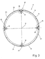
- four wheels 14 are provided, each race 13, two wheels 14 are assigned ( Fig. 1 ).
- Two wheels 14, namely one impeller 14 per race 13 are driven by a common drive, in the illustrated embodiment, an electric motor 15, rotationally.
- the two driven wheels 14 act as friction wheels for Reibradantrieb the drum 11 on the outer circumference of the races 13.
- the wheels 14 and the drive, in particular the electric motor 15 are mounted in the interior of the housing 10 under the drum 11, on a frame, not shown, of the tumble dryer.
- the cylindrical drum 11 has a cylindrical drum wall and two opposite, circular end faces.
- a circular opening specifically a loading opening 16 and a discharge opening 17, is provided in each end face of the drum 11.
- Both the Beladeöf Anlagen 16 and the discharge opening 17 are surrounded by a arranged on the respective end face of the drum 11 Kreisringwandung 18.
- the housing 10 has in each of the opposite end walls 19 via a loading opening 16 and the discharge opening 17 in the drum 11 corresponding, circular housing opening 20 and 21.
- Each housing opening 20 and 21 is closed by a respective cover 44. As a result, during the drying process, the housing 10 can be closed off from the outside in a liquid-tight and temperature-tight manner.
- the drum 11 is formed.
- the drum 11 is composed of a drum cage 22 and a cylindrical jacket plate 23, wherein the jacket plate 23 is formed in several parts, namely composed of a plurality of jacket plate parts 24.
- the jacket plate 23 is formed in several parts, namely composed of a plurality of jacket plate parts 24.
- four equal-sized shroud parts 24 are provided, each extending over about a quarter of the circumference of the shroud 23.
- the drum cage 22 is formed stable according to the invention. This design is such that the drum cage 22 forms a statically self-supporting unit. The drum cage 22 thereby holds the shroud parts 24 together, without the shroud parts 24 being interconnected.
- the drum cage 22 is composed of two races 13 and serving to connect the same struts 25. In the illustrated embodiment, the races 13 are connected by four equally trained struts 25, which are evenly distributed over the circumference of the cylindrical drum 11, so have about quarter circle distances from each other , The opposite end faces of the drum 11 associated races 13 are the same design, preferably have the same dimensions.
- the struts 25 are welded to the races 13. This gives the drum cage 22 the inventively provided in itself stable and self-supporting property.
- the races 13 have in the drum 11 shown here on an L-shaped angle profile.
- a longer leg 26 of this angle profile is circular.
- the outside of the long leg 26 forms a cylindrical running surface 27 of the race 13, whereby the races 13 rest on the wheels 14.
- a lying in the plane of each end short leg 28 of each race 13 extends in the direction of the longitudinal central axis 12.
- the circumferential short leg 28 forms the loading opening 16 and the discharge opening 17 surrounding Kreisringwandung 18 at the respective end face of the drum 11.
- a outwardly facing side of the revolving. short leg 28 of the respective race 13 formed Kreisringwandung 18 of the drum 11 forms a circular sealing surface 29.
- the races 13 are preferably processed after the completion of the drum cage 22.
- the running surfaces 27 and the sealing surfaces 29 of the races 13 are machined by milling, turning, grinding or the like. These operations are preferably carried out during a continuous rotation of the finished drum cage 22.
- the running surfaces 27 extend exactly concentric to the longitudinal center axis 12 and thus also to the axis of rotation of the drum 11.
- the machining of the sealing surfaces 29 exactly perpendicular to the longitudinal central axis 12, whereby the races 13 give the drum 11 a very precise concentricity.
- the struts 25 are formed as elongated profiles. These may be hollow sections or box sections. In the embodiment shown ( Fig. 6 ), the cross-section of each strut 25 is formed approximately ⁇ -like. Accordingly, each of the identically formed struts 25 has a central U-shaped area, the U being open to the outside of the drum 11. At the free outer ends of the parallel legs of the U-shaped central region are adjoined outwardly projecting clamping leg 30. The two clamping legs 30 extend in opposite directions to the outside, so are directed away from each other. The clamping legs 30 are adapted to the outer diameter of the jacket plate 23 of the drum 11 by the inner to the drum 11 facing surfaces of the clamping legs 30 are approximately on the outer diameter of the jacket plate 23.
- the struts 25 completely form a U-profile, so that the struts 25 no Clamping leg 30 have. It is then arranged in between the races 13 are located portion of the U-shaped struts 25, preferably a slightly smaller U-profile with protruding to opposite sides clamping legs.
- the clamping legs of this US profile take over the function of the clamping legs 30.
- the clamping legs - as well as the clamping legs 30 - are formed in the circumferential direction of the drum 11 lying on the U-profile. The lengths of the clamping legs are shorter than the smallest (clear) distance between the races 13th
- the sheath sheet metal parts 24 are dimensioned such that between narrow transverse edges 31 of adjacent sheath sheet metal parts 24 there is a narrow intermediate space, through which the U-shaped middle part of the respective brace 25 protrudes.
- adjacent transverse edge regions of the shroud parts 24 partially, preferably for the most part, the clamping legs 30 of the respective strut 25 (FIGS. Fig. 6 ).
- On the clamping legs 30 outgoing from the transverse edges 31 transversely directed edge regions of two adjacent sheath sheet metal parts 24 are permanently clamped about its entire length, namely clamped, by a respective terminal block which forms a rib 32 in the interior of the drum 11 at the same time.
- Each rib 32 is thus simultaneously a terminal block.
- Each of the identically formed ribs 32 has a hat-shaped cross-section. This is formed from a narrow web 33, extending from the both sides obliquely directed legs 34.
- the legs 34 are oppositely inclined and thereby proceed, starting from the web 33 diverging in the direction of the clamping legs 30 of the respective strut 25.
- the pointing to the clamping legs 30 ends of the legs 34 are angled inwardly to the U-shaped central region of the respective strut 25 and run parallel to the clamping legs 30.
- the ribs 32 are indirectly bolted to the struts 25. These are in the interior of the hat-like profiled rib 32 preferably at least in the radial direction of the drum eleventh elastic coupling members 36 are provided.
- the coupling members 36 are arranged on the web 37 of the U-shaped central portion of the respective strut 25 and connected here to the web 37 of the strut 25.
- At the top of each coupling member 36 carries a nut 38.
- In the nut 38 is a in the Fig. 6 not shown screw through a through hole 39 in the web 36 of the rib 32 can be screwed.
- two or four screws and associated coupling members 36 are provided per strut 25 or rib 32, which are distributed uniformly over the length of the strut 25 and the rib 32 (FIG. Fig. 4 ).
- the coupling member 36 is elastically stretched in the radial direction of the drum 11, so that an upper side of the respective coupling member 36 with the nut 38 comes to rest under the web 33 of the rib 32.
- the elongated coupling members 36 tend to press the rib 32 against the respective strut 25, that is, as seen in the radial direction of the drum 11 to the outside.
- the holes may be formed slot-like in areas of the longitudinal edges of the shell sheet metal parts 24, so that the screws do not hinder thermally induced changes in length of the shell panel parts 24.
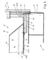
- each largely open end of the drum 11 is sealed against the respective end wall 19 of the housing 10, and that according to the invention by means of a non-contact seal 40.
- the seal 40 is partially shown in the region of the loading opening 16 of the tumble dryer.
- the discharge opening 17 is sealed in the opposite end face of the drum 11 relative to the housing 10.
- the seal 40 is formed between an outer annular region of the annular sealing surface 29 on the outer side of the short leg 28 of each race 13 and a housing opening 20 surrounding the annular region of the end wall 19 on the loading side of the housing 10.
- the front side of the Drum 11 facing inside of the Sitrnwandung 19 of the housing 11 associated with the housing opening 20 surrounding annular sealing lining 41.
- the sealing pad 41 is firmly connected to the inside of the end wall 19 of the housing 10, preferably glued.
- the sealing lining 41 is formed of a soft material, which in particular is heat-resistant. It may be a felt material, a rubber, a plastic or the like.
- the sealing coating 41 partially overlaps the sealing surface 29 of the short leg 28 of the respective race 13 (FIG. Fig. 5 ).
- a narrow annular gap 45 is formed between the sealing surface 29 and the sealing surface 42 facing the sealing surface 41, which brings about a non-contact, labyrinthine sealing of the relevant end face of the drum 11 relative to the housing 10, so that there is no appreciable exchange of air between the inside of the drum 11 and the outside thereof, in particular a lower part 43 of the housing 10, can take place.
- an air exchange with the environment is prevented by the cover 44.
- the lid 44 closes when in-service continuous washing machine located on the loading side housing opening 20 and also a central part of the loading opening 16 of the drum 11, but by an annular gap 45 no Contact with the rotating drum 11 can take place.
- the invention is suitable not only for the above-described continuous tumble dryer with a loading opening 16 on one end face of the drum 11 at a discharge opening 17 on the opposite end face of the drum 11; Rather, for other types of dryers, especially those that only at one end of the Drum 11 have an opening which also serves as a loading and unloading.
- a seal 40 needs to be present only on that end face of the drum 11, which also serves for loading and unloading the laundry.
- the opposite, closed end face of the drum 11 then requires no seal 40.
- the drum is formed as described above, in particular provided with a self-supporting drum cage 22 and shell plate parts 24, the continuous over the entire length of the transverse edges 31 and transverse edge regions by clamping the struts 25 of the drum cage 22 are attached.
Landscapes
- Engineering & Computer Science (AREA)
- Textile Engineering (AREA)
- Detail Structures Of Washing Machines And Dryers (AREA)
- Drying Of Solid Materials (AREA)
Claims (11)
- Séchoir, en particulier séchoir à linge, comprenant un tambour cylindrique (11) pouvant être entraîné en rotation, qui présente des anneaux de roulement (13) de forme circulaire, connectés par des entretoises (25), pour former une cage de tambour (22), et une tôle d'enveloppe (23) formée de plusieurs parties de tôle d'enveloppe (24) individuelles; caractérisé en ce que les parties de tôle d'enveloppe (24) peuvent être connectées au moins en partie par serrage à la cage de tambour (22).
- Séchoir selon la revendication 1, caractérisé en ce que des arêtes transversales (31) ou des régions de bord des parties de tôle d'enveloppe (24) partant des arêtes transversales (31) peuvent être fixées par serrage aux entretoises (25), de préférence les arêtes transversales (31), notamment les régions des parties de tôle d'enveloppe (24) qui leur sont adjacentes, peuvent être fixées par serrage par les baguettes de serrage aux entretoises (25), en particulier par engagement par force et/ou par frottement.
- Séchoir selon la revendication 1 ou 2, caractérisé en ce que des arêtes transversales opposées (31) dans la région de chaque entretoise (25) et de chaque baguette de serrage ou des régions de bord de parties de tôle d'enveloppe (24) adjacentes s'y raccordant peuvent être fixées par serrage de manière continue, de préférence sur essentiellement toute la longueur des arêtes transversales (31) ou des régions de bord s'y raccordant.
- Séchoir selon l'une quelconque des revendications précédentes, caractérisé en ce que les arêtes transversales (31) ou les régions de bord des parties de tôle d'enveloppe (24) s'y raccordant peuvent être fixées par serrage entre des branches de serrage (30) des entretoises (25) saillant sur des côtés opposés des entretoises (25) et des branches de pression (35) des baguettes de serrage s'étendant approximativement parallèlement aux branches de serrage (30).
- Séchoir selon l'une quelconque des revendications précédentes, caractérisé en ce que dans chaque cas, une baguette de serrage est connectée de manière desserrable à une entretoise (25), notamment par vissage, la distance entre les baguettes de serrage, notamment les branches de pression (35) aux branches de serrage (30) de l'entretoise respective (25), peut être modifiée de préférence élastiquement ou par ressort, pour une fixation par serrage continue des arêtes transversales (31) ou des régions de bord des parties de tôle d'enveloppe (24) s'y raccordant sur la cage de tambour (22).
- Séchoir selon l'une quelconque des revendications précédentes, caractérisé en ce que les parties de tôle d'enveloppe (24) sont fixées en outre avec leurs bords longitudinaux s'étendant en forme d'arc de cercle aux anneaux de roulement (13), de préférence par vissage.
- Séchoir selon l'une quelconque des revendications précédentes, caractérisé en ce que les baguettes de serrage sont réalisées sous forme de nervures (32) saillant vers l'intérieur du tambour (11).
- Séchoir selon l'une quelconque des revendications précédentes, caractérisé en ce que les anneaux de roulement (13) forment avec les entretoises (25) une cage de tambour stable (22).
- Séchoir selon l'une quelconque des revendications précédentes, caractérisé en ce que les anneaux de roulement (13) sont connectés fixement aux anneaux de roulement (13) par plusieurs entretoises (25) réparties de préférence uniformément sur la périphérie du tambour (11) et s'étendant parallèlement à un axe médian longitudinal (12) du tambour (11).
- Séchoir selon l'une quelconque des revendications précédentes, caractérisé en ce que les anneaux de roulement (13) sont disposés sur les côtés frontaux de la cage de tambour (22) ou forment des côtés frontaux de la cage de tambour (22), et les entretoises (25) pour la connexion des anneaux de roulement (13) sont disposées entre les côtés frontaux de la cage de tambour (22).
- Séchoir selon l'une quelconque des revendications précédentes, caractérisé en ce que les entretoises (25) sont profilées en section transversale, notamment sont réalisées en forme de cassettes ou de profilés creux.
Applications Claiming Priority (2)
| Application Number | Priority Date | Filing Date | Title |
|---|---|---|---|
| DE10253113A DE10253113A1 (de) | 2002-11-13 | 2002-11-13 | Trockner, insbesondere Wäschetrockner |
| DE10253113 | 2002-11-13 |
Publications (3)
| Publication Number | Publication Date |
|---|---|
| EP1420103A2 EP1420103A2 (fr) | 2004-05-19 |
| EP1420103A3 EP1420103A3 (fr) | 2004-06-16 |
| EP1420103B1 true EP1420103B1 (fr) | 2009-11-04 |
Family
ID=32115516
Family Applications (1)
| Application Number | Title | Priority Date | Filing Date |
|---|---|---|---|
| EP03025842A Expired - Lifetime EP1420103B1 (fr) | 2002-11-13 | 2003-11-11 | Séchoir, en particulier séchoir à linge |
Country Status (3)
| Country | Link |
|---|---|
| EP (1) | EP1420103B1 (fr) |
| DE (2) | DE10253113A1 (fr) |
| ES (1) | ES2334437T3 (fr) |
Families Citing this family (4)
| Publication number | Priority date | Publication date | Assignee | Title |
|---|---|---|---|---|
| DE102005009230B4 (de) * | 2005-02-25 | 2008-12-24 | Jensen-Senking Gmbh | Trocknungsanlage mit einer Trocknerdichtung und Zentriermitteln |
| ES2369166T3 (es) * | 2007-09-03 | 2011-11-28 | Arçelik Anonim Sirketi | Secadora. |
| DE102007057606A1 (de) | 2007-11-28 | 2009-06-04 | Basell Polyolefine Gmbh | Modular aufgebaute Rotationstrommel für Elektro- und Haushaltsgeräte |
| CN108532209B (zh) * | 2018-05-02 | 2024-02-13 | 浙江喜创联电子商务有限公司 | 一种具有杀菌作用的筒体 |
Family Cites Families (6)
| Publication number | Priority date | Publication date | Assignee | Title |
|---|---|---|---|---|
| US2803142A (en) * | 1954-01-15 | 1957-08-20 | Lovell Mfg Co | Friction roll drum support and drive |
| US3316658A (en) * | 1965-04-05 | 1967-05-02 | George N Strike | Two-sided tumbler |
| US3382587A (en) * | 1966-09-06 | 1968-05-14 | Mc Graw Edison Co | Clothes conditioning-drying machine |
| DE1954053A1 (de) * | 1969-07-19 | 1971-01-28 | Zanussi A Spa Industrie | Trockenschrank,insbesondere fuer Bekleidungsartikel,Waesche u.dgl. |
| DE3438574A1 (de) * | 1984-10-20 | 1986-04-24 | Herbert Kannegiesser Gmbh + Co, 4973 Vlotho | Trommel fuer waeschetrockner |
| DE19615822C1 (de) * | 1996-04-20 | 1997-05-07 | Bauknecht Hausgeraete | Wäschetrockner |
-
2002
- 2002-11-13 DE DE10253113A patent/DE10253113A1/de not_active Withdrawn
-
2003
- 2003-11-11 ES ES03025842T patent/ES2334437T3/es not_active Expired - Lifetime
- 2003-11-11 DE DE50312085T patent/DE50312085D1/de not_active Expired - Lifetime
- 2003-11-11 EP EP03025842A patent/EP1420103B1/fr not_active Expired - Lifetime
Also Published As
| Publication number | Publication date |
|---|---|
| DE50312085D1 (de) | 2009-12-17 |
| EP1420103A3 (fr) | 2004-06-16 |
| EP1420103A2 (fr) | 2004-05-19 |
| ES2334437T3 (es) | 2010-03-10 |
| DE10253113A1 (de) | 2004-05-27 |
Similar Documents
| Publication | Publication Date | Title |
|---|---|---|
| DE3512711C2 (fr) | ||
| EP0828029B1 (fr) | Cylindre de calandrage ayant une couverture d'une matière synthétique élastique | |
| DE4109467A1 (de) | Dokumentenvernichter | |
| DE1510359B2 (de) | Walze zum Entwässern von Fasersuspensionen | |
| DE2342421A1 (de) | Trommel mit gitterkonstruktion | |
| WO2006072505A1 (fr) | Dispositif et procede de production et/ou de transformation d'une bande de matiere fibreuse | |
| EP1420103B1 (fr) | Séchoir, en particulier séchoir à linge | |
| EP1205590B1 (fr) | Dispositif pour le traitement au mouillé du linge et étanchéité pour un tel dispositif | |
| EP0305706A2 (fr) | Tambour rotatif | |
| DE2203681A1 (de) | Wälzlagereinheit für die fliegend gelagerte Trommel einer Waschmaschine, Zentrifuge od.dgl | |
| DE3040359C2 (de) | Als Wärmetauscher dienende Walze | |
| DE60222944T2 (de) | Supraleitendes magnetisches lager | |
| EP0385208B1 (fr) | Appareil pour faire passer un fluide de traitement à travers une matière textile | |
| EP1909051A1 (fr) | Tambour ou segment de tambour pour un dispositif de séchage de matériau en vrac et procédé de fabrication d'un tambour ou d'un segment de tambour. | |
| EP2780158B1 (fr) | Presse à vis ii | |
| EP0861989B1 (fr) | Couplage élastique entre un cylindre et un dispositif de palier ou d'entraínement aligné dans l'axe | |
| EP2963172B1 (fr) | Dispositif destiné au traitement humide du linge | |
| EP0140016B1 (fr) | Couronne dentée | |
| DE102014218252B4 (de) | Rollkörper für eine Lagerrolle, Lagerrolle mit einem solchen und Haushaltsgerät mit einer solchen | |
| EP0671497A2 (fr) | Rouleau, notamment pour des machines de traitement des matières textiles | |
| DE2163734C3 (de) | Labyrinthdichtung zum Abdichten zweier relativ zueinander drehbarer Bauteile | |
| EP0950747A1 (fr) | Dispositif pour faire passer en continu un fluide chaud de traitement à travers une matière textile ou analogue | |
| EP1081266B1 (fr) | Procédé et dispositif d'humidification en particulier pour le lavage du linge | |
| CH629045A5 (de) | Elektrische maschine mit einem axialluefter. | |
| DE3145901A1 (de) | "drehtrommel" |
Legal Events
| Date | Code | Title | Description |
|---|---|---|---|
| PUAI | Public reference made under article 153(3) epc to a published international application that has entered the european phase |
Free format text: ORIGINAL CODE: 0009012 |
|
| PUAL | Search report despatched |
Free format text: ORIGINAL CODE: 0009013 |
|
| AK | Designated contracting states |
Kind code of ref document: A2 Designated state(s): AT BE BG CH CY CZ DE DK EE ES FI FR GB GR HU IE IT LI LU MC NL PT RO SE SI SK TR |
|
| AX | Request for extension of the european patent |
Extension state: AL LT LV MK |
|
| AK | Designated contracting states |
Kind code of ref document: A3 Designated state(s): AT BE BG CH CY CZ DE DK EE ES FI FR GB GR HU IE IT LI LU MC NL PT RO SE SI SK TR |
|
| AX | Request for extension of the european patent |
Extension state: AL LT LV MK |
|
| 17P | Request for examination filed |
Effective date: 20041214 |
|
| AKX | Designation fees paid |
Designated state(s): BE DE ES FR |
|
| RBV | Designated contracting states (corrected) |
Designated state(s): BE DE ES FR |
|
| GRAP | Despatch of communication of intention to grant a patent |
Free format text: ORIGINAL CODE: EPIDOSNIGR1 |
|
| GRAS | Grant fee paid |
Free format text: ORIGINAL CODE: EPIDOSNIGR3 |
|
| GRAA | (expected) grant |
Free format text: ORIGINAL CODE: 0009210 |
|
| AK | Designated contracting states |
Kind code of ref document: B1 Designated state(s): BE DE ES FR |
|
| REF | Corresponds to: |
Ref document number: 50312085 Country of ref document: DE Date of ref document: 20091217 Kind code of ref document: P |
|
| REG | Reference to a national code |
Ref country code: ES Ref legal event code: FG2A Ref document number: 2334437 Country of ref document: ES Kind code of ref document: T3 |
|
| BERE | Be: lapsed |
Owner name: HERBERT KANNEGIESSER G.M.B.H. Effective date: 20091130 |
|
| PLBE | No opposition filed within time limit |
Free format text: ORIGINAL CODE: 0009261 |
|
| STAA | Information on the status of an ep patent application or granted ep patent |
Free format text: STATUS: NO OPPOSITION FILED WITHIN TIME LIMIT |
|
| 26N | No opposition filed |
Effective date: 20100805 |
|
| PG25 | Lapsed in a contracting state [announced via postgrant information from national office to epo] |
Ref country code: BE Free format text: LAPSE BECAUSE OF NON-PAYMENT OF DUE FEES Effective date: 20091130 |
|
| PGFP | Annual fee paid to national office [announced via postgrant information from national office to epo] |
Ref country code: FR Payment date: 20121130 Year of fee payment: 10 |
|
| REG | Reference to a national code |
Ref country code: FR Ref legal event code: ST Effective date: 20140731 |
|
| PG25 | Lapsed in a contracting state [announced via postgrant information from national office to epo] |
Ref country code: FR Free format text: LAPSE BECAUSE OF NON-PAYMENT OF DUE FEES Effective date: 20131202 |
|
| PGFP | Annual fee paid to national office [announced via postgrant information from national office to epo] |
Ref country code: DE Payment date: 20161129 Year of fee payment: 14 |
|
| PGFP | Annual fee paid to national office [announced via postgrant information from national office to epo] |
Ref country code: ES Payment date: 20161027 Year of fee payment: 14 |
|
| REG | Reference to a national code |
Ref country code: DE Ref legal event code: R119 Ref document number: 50312085 Country of ref document: DE |
|
| PG25 | Lapsed in a contracting state [announced via postgrant information from national office to epo] |
Ref country code: DE Free format text: LAPSE BECAUSE OF NON-PAYMENT OF DUE FEES Effective date: 20180602 |
|
| REG | Reference to a national code |
Ref country code: ES Ref legal event code: FD2A Effective date: 20181226 |
|
| PG25 | Lapsed in a contracting state [announced via postgrant information from national office to epo] |
Ref country code: ES Free format text: LAPSE BECAUSE OF NON-PAYMENT OF DUE FEES Effective date: 20171112 |