EP1420168A1 - Radiallüfter - Google Patents
Radiallüfter Download PDFInfo
- Publication number
- EP1420168A1 EP1420168A1 EP03257081A EP03257081A EP1420168A1 EP 1420168 A1 EP1420168 A1 EP 1420168A1 EP 03257081 A EP03257081 A EP 03257081A EP 03257081 A EP03257081 A EP 03257081A EP 1420168 A1 EP1420168 A1 EP 1420168A1
- Authority
- EP
- European Patent Office
- Prior art keywords
- casing
- centrifugal blower
- bellmouth
- air intake
- air
- Prior art date
- Legal status (The legal status is an assumption and is not a legal conclusion. Google has not performed a legal analysis and makes no representation as to the accuracy of the status listed.)
- Granted
Links
- 238000004378 air conditioning Methods 0.000 description 8
- 238000000465 moulding Methods 0.000 description 5
- 238000004519 manufacturing process Methods 0.000 description 3
- 230000015572 biosynthetic process Effects 0.000 description 2
- 239000011347 resin Substances 0.000 description 2
- 229920005989 resin Polymers 0.000 description 2
- 230000003068 static effect Effects 0.000 description 2
- 230000003247 decreasing effect Effects 0.000 description 1
- 238000001746 injection moulding Methods 0.000 description 1
- 230000003014 reinforcing effect Effects 0.000 description 1
Images



Classifications
-
- F—MECHANICAL ENGINEERING; LIGHTING; HEATING; WEAPONS; BLASTING
- F04—POSITIVE - DISPLACEMENT MACHINES FOR LIQUIDS; PUMPS FOR LIQUIDS OR ELASTIC FLUIDS
- F04D—NON-POSITIVE-DISPLACEMENT PUMPS
- F04D25/00—Pumping installations or systems
- F04D25/16—Combinations of two or more pumps ; Producing two or more separate gas flows
- F04D25/166—Combinations of two or more pumps ; Producing two or more separate gas flows using fans
-
- F—MECHANICAL ENGINEERING; LIGHTING; HEATING; WEAPONS; BLASTING
- F04—POSITIVE - DISPLACEMENT MACHINES FOR LIQUIDS; PUMPS FOR LIQUIDS OR ELASTIC FLUIDS
- F04D—NON-POSITIVE-DISPLACEMENT PUMPS
- F04D29/00—Details, component parts, or accessories
- F04D29/40—Casings; Connections of working fluid
- F04D29/42—Casings; Connections of working fluid for radial or helico-centrifugal pumps
- F04D29/4206—Casings; Connections of working fluid for radial or helico-centrifugal pumps especially adapted for elastic fluid pumps
- F04D29/4213—Casings; Connections of working fluid for radial or helico-centrifugal pumps especially adapted for elastic fluid pumps suction ports
Definitions
- the present invention relates to a centrifugal blower, and, more specifically, to a centrifugal blower suitable particularly for an air conditioning system for vehicles, in which a bellmouth is provided to an air intake port of a casing.
- a conventional centrifugal blower used in an air conditioning system for vehicles is constructed, for example, as shown in Figs. 7 and 8 (for example, JP-A-8-109897).
- a centrifugal blower 100 has a motor 101, and multiblade fans 104 and 105 are provided on the ends of rotary shafts 102 and 103 connected to the motor 101.
- Fans 104 and 105 are contained in casings 106 and 107, respectively.
- Air intake ports 108 and 109 are provided on both sides of casing 106, and air intake ports 111 and 112 are provided on both sides of casing 107.
- Air sucked through air intake ports 108 and 109 is discharged from the radial inside of fan 104 to the radial outside of the fan 104, and sent to a heater unit (not shown) of an air conditioning system through a flow path 110 formed in casing 106.
- air sucked through air intake ports 111 and 112 is discharged from the radial inside of fan 105 to the radial outside of the fan 105, and sent to the heater unit of the air conditioning system through a flow path 113 formed in casing 107.
- Each of casings 106 and 107 are formed from two casing forming members 114 and 115 capable of being divided into each other in the arrow directions (in the radial direction of the multiblade fan) shown in Fig. 8.
- centrifugal blower In a centrifugal blower, generally it is considered that, if a bellmouth is provided to each air intake port, because residence or back flow of air near the air intake port is prevented and the air flow may be stabilized, reduction of blast performance and generation of noise at the time of air suction may be prevented.
- a bellmouth is provided to each of casings 106 and 107 integrally with the casing, the structure of a mold for molding the casing may become complicated. Therefore, at least in a double-axis type centrifugal blower as described above, a centrifugal blower having a bellmouth on each air intake port integrally with the air intake port has not been known as long as the inventor of the present invention has investigated.
- centrifugal blower which can easily provide a bellmouth to each air intake port without use of a complicated mold for molding a casing forming member and without increase of number of parts, thereby effectively preventing reduction of the blast performance of the blower and generation of noise from the blower.
- a centrifugal blower comprises a multiblade fan having a plurality of blades disposed around a rotary shaft in the circumferential direction, and a casing containing the multiblade fan, and air sucked through an air intake port opened on the casing is sucked from a radial inside to a radial outside through a portion between adjacent blades.
- the centrifugal blower is characterized in that a bellmouth having a diameter increasing toward an outside of the casing is provided to the air intake port.
- the casing may be made of a resin.
- the bellmouth may be formed integrally with the casing.
- the number of parts is reduced as compared with a case where the bellmouth is formed separately from the casing.
- the casing is molded (for example, injection molding), it becomes possible to mold the casing and the bellmouth simultaneously. Therefore, the cost for manufacturing the casing, ultimately, the whole of the blower, may be reduced.
- the casing may be formed from a plurality of casing forming members capable of being divided into each other in a radial direction of the multiblade fan.
- the casing is formed from two casing forming members capable of being divided into each other in the radial direction of the multiblade fan.
- the present invention may be applied to both of a single-axis type centrifugal blower, in which a multiblade fan is provided on one side of a rotary shaft, and a double-axis type centrifugal blower, in which the multiblade fan is provided on each end of the rotary shaft to form a double-axis type fan structure.
- a single-axis type centrifugal blower in which a multiblade fan is provided on one side of a rotary shaft
- a double-axis type centrifugal blower in which the multiblade fan is provided on each end of the rotary shaft to form a double-axis type fan structure.
- the advantage according to the present invention is great in a case where the present invention is applied to a double-axis type centrifugal blower.
- the bellmouth having a diameter increasing toward the outside of the casing is provided to the air intake port opened on the casing, residence and back flow of air near the air intake port may be prevented, and the air flow may be stabilized. Therefore, decrease of the blast performance ascribed to reduction of the amount of sucked air and generation of noise at the time of air suction may be effectively prevented. Since this bellmouth extends toward the outside of the casing, when the casing forming member is molded, the bellmouth portion may be easily molded integrally with the casing forming member by a simple mold without a complicated slide structure and the like. Further, increase of the number parts may be prevented by forming the bellmouth portion integrally with the casing forming member. Especially, the bellmouth may be easily formed by forming the casing from a plurality of casing forming members capable of being divided into each other in the radial direction of the multiblade fan.
- a desirable bellmouth may be formed on each air intake port easily and inexpensively without using a complicated mold structure.
- a centrifugal blower having a desirable property may be manufactured easily and inexpensively.
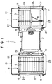
- Figs. 1 to 4 show a centrifugal blower according to an embodiment of the present invention.
- a centrifugal blower 1 is constructed as a blower used in an air conditioning system for vehicles.
- Centrifugal blower 1 has a motor 2, and it is constructed as a double-axis type centrifugal blower.
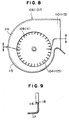
- Multiblade fans 6 and 7 each having a plurality of blades 5 are provided at the ends of rotary shafts 3 and 4 of motor 2. The plurality of blades 5 are disposed around each of rotary shafts 3 and 4 in the circumferential direction, as shown in Fig. 4.
- Each of rotary shafts 3 and 4 are connected to the plurality of blades 5 via a drive plate 8 formed as a disc-like plate, and the drive plates 8 and blades 5 are rotated accompanying with the rotation of rotary shafts 3 and 4 in a predetermined direction as shown by the arrow in Fig. 4.
- a connection ring 9 is provided on blades 5 of each of multiblade fans 6 and 7 for connecting the blades 5 to each other and reinforcing and maintaining the connection formation.
- Multiblade fans 6 and 7 are contained in scroll-type casings 10 and 11, respectively.
- Air intake ports 12 and 13 are opened on casing 10, and air sucked through air intake ports 12 and 13 is discharged from the radial inside of multiblade fan 6 to the radial outside of the multiblade fan 6.
- the discharged air is sent to a heater unit (not shown) of an air conditioning system through a flow path 14.
- air intake ports 15 and 16 are opened on casing 11, and air sucked through air intake ports 15 and 16 is discharged from the radial inside of multiblade fan 7 to the radial outside of the multiblade fan 7.
- the discharged air is sent to the heater unit of the air conditioning system through a flow path 17.
- Bellmouths 18, 19, 20 and 21 are provided to respective air intake ports 12, 13, 15 and 16. Each of bellmouths 18, 19, 20 and 21 extends from each of air intake ports 12, 13, 15 and 16 toward the outside of casing 10 or 11, and the diameter of each bellmouth increases toward the outside of the casing. Further, each of bellmouths 18, 19, 20 and 21 is formed integrally with casing 10 or 11. Each casing with each bellmouth is formed from, for example, a resin.
- each of casings 10 and 11 is formed from two casing forming members 22 and 23 capable of being divided into each other in the radial direction of multiblade fan 6 or 7.
- a semi-circular bellmouth forming portion 24 or 25 is provided on each casing forming member 22 or 23 .
- Divided casing forming members 22 and 23 forms casing 10 or 11 by being connected to each other, and each bellmouth having a circular shape is formed by connection of bellmouth forming portions 24 and 25 at the time of the formation of casing 10 or 11.
- casing forming members 22 and 23 are formed so as to be divided in the arrow directions shown in Fig. 2. Therefore, by designing the parting lines of molds for molding casing forming members 22 and 23 so as to meet with the division lines shown in Fig. 2, bellmouth forming portions 24 and 25 may be easily molded integrally with casing forming members 22 and 23 without using a complicated structure such as a slide mechanism and the like.
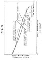
- a usage range for an air conditioning system which exists between the resistance curve at the time of minimum load and the resistance curve at the time of maximum load, is enlarged as compared with that in the conventional centrifugal blower 100, and the advantage for improving the blast performance is exhibited.
- the above-described centrifugal blower 1 having the respective bellmouths exhibits an excellent performance.
- bellmouths 18 and 19 are formed integrally with casing 10 and bellmouths 20 and 21 are formed integrally with casing 11, the number of parts does not increase, and the cost up due to increase of the number of parts may be prevented.
- casing forming members 22 and 23 and bellmouth forming portions 24 and 25 extending toward the outside of the casing forming members can be simultaneously molded by using a simple mold without employing a complicated structure such as a slide mechanism, the cost for the molding and the cost for manufacturing the mold may be greatly reduced.
- centrifugal blower 1 is explained as to a double-axis type centrifugal blower, the present invention may be applied to a single-axis type centrifugal blower.
Landscapes
- Engineering & Computer Science (AREA)
- Mechanical Engineering (AREA)
- General Engineering & Computer Science (AREA)
- Structures Of Non-Positive Displacement Pumps (AREA)
Applications Claiming Priority (2)
| Application Number | Priority Date | Filing Date | Title |
|---|---|---|---|
| JP2002333953 | 2002-11-18 | ||
| JP2002333953A JP2004169579A (ja) | 2002-11-18 | 2002-11-18 | 遠心式送風機 |
Publications (2)
| Publication Number | Publication Date |
|---|---|
| EP1420168A1 true EP1420168A1 (de) | 2004-05-19 |
| EP1420168B1 EP1420168B1 (de) | 2006-07-12 |
Family
ID=32171441
Family Applications (1)
| Application Number | Title | Priority Date | Filing Date |
|---|---|---|---|
| EP20030257081 Expired - Lifetime EP1420168B1 (de) | 2002-11-18 | 2003-11-10 | Radiallüfter |
Country Status (4)
| Country | Link |
|---|---|
| EP (1) | EP1420168B1 (de) |
| JP (1) | JP2004169579A (de) |
| CN (1) | CN1500995A (de) |
| DE (1) | DE60306733T2 (de) |
Cited By (2)
| Publication number | Priority date | Publication date | Assignee | Title |
|---|---|---|---|---|
| EP2314880A4 (de) * | 2008-07-10 | 2011-08-10 | Mitsubishi Electric Corp | Sirocco-lüfter und diesen verwendende klimaanlage |
| CN103307039A (zh) * | 2013-06-19 | 2013-09-18 | 上海酷风汽车部件有限公司 | 一种双轴风机装配风轮的装置 |
Families Citing this family (4)
| Publication number | Priority date | Publication date | Assignee | Title |
|---|---|---|---|---|
| JP4722555B2 (ja) * | 2004-07-09 | 2011-07-13 | サンデン株式会社 | 遠心式送風機 |
| JP4747542B2 (ja) * | 2004-09-28 | 2011-08-17 | ダイキン工業株式会社 | 送風装置及び空気調和装置 |
| CN104696244A (zh) * | 2015-03-09 | 2015-06-10 | 黎雅伟 | 滤尘风机 |
| CN106640715A (zh) * | 2016-10-20 | 2017-05-10 | 上海朗兹环保科技有限公司 | 一种风系统装置及空气净化器 |
Citations (6)
| Publication number | Priority date | Publication date | Assignee | Title |
|---|---|---|---|---|
| US1875881A (en) * | 1931-01-27 | 1932-09-06 | American Blower Corp | Fan housing construction |
| US3846040A (en) * | 1972-06-16 | 1974-11-05 | D Dennis | Blower housing |
| EP0837246A2 (de) * | 1996-10-15 | 1998-04-22 | PM-Luft AB | Lüftergehäuse zur Luftzuführung eines Ventilationssystems |
| US6206633B1 (en) * | 1998-07-08 | 2001-03-27 | Denso Corporation | Case assembling structure of blower unit |
| EP1178215A2 (de) * | 2000-08-04 | 2002-02-06 | Calsonic Kansei Corporation | Kreiselgebläse |
| US20020021963A1 (en) * | 2000-08-17 | 2002-02-21 | Kim Sung Chun | Blowing fan assembly for a window-type air conditioner |
-
2002
- 2002-11-18 JP JP2002333953A patent/JP2004169579A/ja active Pending
-
2003
- 2003-11-10 DE DE2003606733 patent/DE60306733T2/de not_active Expired - Lifetime
- 2003-11-10 EP EP20030257081 patent/EP1420168B1/de not_active Expired - Lifetime
- 2003-11-18 CN CNA200310117907A patent/CN1500995A/zh active Pending
Patent Citations (6)
| Publication number | Priority date | Publication date | Assignee | Title |
|---|---|---|---|---|
| US1875881A (en) * | 1931-01-27 | 1932-09-06 | American Blower Corp | Fan housing construction |
| US3846040A (en) * | 1972-06-16 | 1974-11-05 | D Dennis | Blower housing |
| EP0837246A2 (de) * | 1996-10-15 | 1998-04-22 | PM-Luft AB | Lüftergehäuse zur Luftzuführung eines Ventilationssystems |
| US6206633B1 (en) * | 1998-07-08 | 2001-03-27 | Denso Corporation | Case assembling structure of blower unit |
| EP1178215A2 (de) * | 2000-08-04 | 2002-02-06 | Calsonic Kansei Corporation | Kreiselgebläse |
| US20020021963A1 (en) * | 2000-08-17 | 2002-02-21 | Kim Sung Chun | Blowing fan assembly for a window-type air conditioner |
Cited By (2)
| Publication number | Priority date | Publication date | Assignee | Title |
|---|---|---|---|---|
| EP2314880A4 (de) * | 2008-07-10 | 2011-08-10 | Mitsubishi Electric Corp | Sirocco-lüfter und diesen verwendende klimaanlage |
| CN103307039A (zh) * | 2013-06-19 | 2013-09-18 | 上海酷风汽车部件有限公司 | 一种双轴风机装配风轮的装置 |
Also Published As
| Publication number | Publication date |
|---|---|
| CN1500995A (zh) | 2004-06-02 |
| DE60306733D1 (de) | 2006-08-24 |
| JP2004169579A (ja) | 2004-06-17 |
| DE60306733T2 (de) | 2006-11-16 |
| EP1420168B1 (de) | 2006-07-12 |
Similar Documents
| Publication | Publication Date | Title |
|---|---|---|
| AU2005208338B2 (en) | Centrifugal blower | |
| US9033655B2 (en) | Multiblade air blower | |
| KR100818429B1 (ko) | 고효율의 단일형 원심형 블로워 | |
| US9322413B2 (en) | Centrifugal fan | |
| US8870541B2 (en) | Centrifugal multiblade fan | |
| US9624932B2 (en) | Centrifugal fan and air conditioner having the same | |
| US7591633B2 (en) | Centrifugal blower for air handling equipment | |
| JP5131093B2 (ja) | 遠心式送風機 | |
| US6254343B1 (en) | Low-noise cooling fan for electronic components and method of making the same | |
| EP1420168B1 (de) | Radiallüfter | |
| US20210270287A1 (en) | Centrifugal fan and centrifugal blower | |
| US7670115B2 (en) | Turbo fan | |
| CN101542127B (zh) | 送风机的叶轮的凸台结构以及具有该凸台结构的送风机的叶轮 | |
| US7255533B2 (en) | Centrifugal fan | |
| KR101309084B1 (ko) | 이중 블레이드를 갖는 시로코 팬 | |
| JP2003097488A (ja) | 遠心送風機及び空気調和機 | |
| CN115917159B (zh) | 多叶片叶轮以及离心送风机 | |
| JP4500038B2 (ja) | 遠心式多翼ファン | |
| CN112400066B (zh) | 送风机 | |
| KR100725813B1 (ko) | 원심팬 | |
| KR100393563B1 (ko) | 터보팬 | |
| CN1727694A (zh) | 离心式多叶风扇 | |
| JP3367368B2 (ja) | 送風装置 | |
| WO2021049536A1 (ja) | 送風ファン | |
| JPS6085291A (ja) | 渦流送風機 |
Legal Events
| Date | Code | Title | Description |
|---|---|---|---|
| PUAI | Public reference made under article 153(3) epc to a published international application that has entered the european phase |
Free format text: ORIGINAL CODE: 0009012 |
|
| AK | Designated contracting states |
Kind code of ref document: A1 Designated state(s): AT BE BG CH CY CZ DE DK EE ES FI FR GB GR HU IE IT LI LU MC NL PT RO SE SI SK TR |
|
| AX | Request for extension of the european patent |
Extension state: AL LT LV MK |
|
| 17P | Request for examination filed |
Effective date: 20041105 |
|
| AKX | Designation fees paid |
Designated state(s): DE FR IT |
|
| 17Q | First examination report despatched |
Effective date: 20050311 |
|
| GRAP | Despatch of communication of intention to grant a patent |
Free format text: ORIGINAL CODE: EPIDOSNIGR1 |
|
| GRAS | Grant fee paid |
Free format text: ORIGINAL CODE: EPIDOSNIGR3 |
|
| GRAA | (expected) grant |
Free format text: ORIGINAL CODE: 0009210 |
|
| AK | Designated contracting states |
Kind code of ref document: B1 Designated state(s): DE FR IT |
|
| PG25 | Lapsed in a contracting state [announced via postgrant information from national office to epo] |
Ref country code: IT Free format text: LAPSE BECAUSE OF FAILURE TO SUBMIT A TRANSLATION OF THE DESCRIPTION OR TO PAY THE FEE WITHIN THE PRESCRIBED TIME-LIMIT;WARNING: LAPSES OF ITALIAN PATENTS WITH EFFECTIVE DATE BEFORE 2007 MAY HAVE OCCURRED AT ANY TIME BEFORE 2007. THE CORRECT EFFECTIVE DATE MAY BE DIFFERENT FROM THE ONE RECORDED. Effective date: 20060712 |
|
| REF | Corresponds to: |
Ref document number: 60306733 Country of ref document: DE Date of ref document: 20060824 Kind code of ref document: P |
|
| ET | Fr: translation filed | ||
| PLBE | No opposition filed within time limit |
Free format text: ORIGINAL CODE: 0009261 |
|
| STAA | Information on the status of an ep patent application or granted ep patent |
Free format text: STATUS: NO OPPOSITION FILED WITHIN TIME LIMIT |
|
| 26N | No opposition filed |
Effective date: 20070413 |
|
| REG | Reference to a national code |
Ref country code: FR Ref legal event code: PLFP Year of fee payment: 13 |
|
| PGFP | Annual fee paid to national office [announced via postgrant information from national office to epo] |
Ref country code: FR Payment date: 20151119 Year of fee payment: 13 |
|
| REG | Reference to a national code |
Ref country code: DE Ref legal event code: R082 Ref document number: 60306733 Country of ref document: DE Representative=s name: PRUEFER & PARTNER MBB PATENTANWAELTE RECHTSANW, DE Ref country code: DE Ref legal event code: R081 Ref document number: 60306733 Country of ref document: DE Owner name: SANDEN HOLDINGS CORPORATION, LSESAKI-SHI, JP Free format text: FORMER OWNER: SANDEN CORP., ISESAKI, GUNMA, JP |
|
| REG | Reference to a national code |
Ref country code: FR Ref legal event code: CD Owner name: SANDEN HOLDINGS CORPORATION, JP Effective date: 20160525 |
|
| PGFP | Annual fee paid to national office [announced via postgrant information from national office to epo] |
Ref country code: DE Payment date: 20161121 Year of fee payment: 14 |
|
| PGFP | Annual fee paid to national office [announced via postgrant information from national office to epo] |
Ref country code: IT Payment date: 20161123 Year of fee payment: 14 |
|
| REG | Reference to a national code |
Ref country code: FR Ref legal event code: ST Effective date: 20170731 |
|
| PG25 | Lapsed in a contracting state [announced via postgrant information from national office to epo] |
Ref country code: FR Free format text: LAPSE BECAUSE OF NON-PAYMENT OF DUE FEES Effective date: 20161130 |
|
| REG | Reference to a national code |
Ref country code: DE Ref legal event code: R119 Ref document number: 60306733 Country of ref document: DE |
|
| PG25 | Lapsed in a contracting state [announced via postgrant information from national office to epo] |
Ref country code: IT Free format text: LAPSE BECAUSE OF NON-PAYMENT OF DUE FEES Effective date: 20171110 Ref country code: DE Free format text: LAPSE BECAUSE OF NON-PAYMENT OF DUE FEES Effective date: 20180602 |