EP1420171A2 - Vérin hydraulique - Google Patents
Vérin hydraulique Download PDFInfo
- Publication number
- EP1420171A2 EP1420171A2 EP03019422A EP03019422A EP1420171A2 EP 1420171 A2 EP1420171 A2 EP 1420171A2 EP 03019422 A EP03019422 A EP 03019422A EP 03019422 A EP03019422 A EP 03019422A EP 1420171 A2 EP1420171 A2 EP 1420171A2
- Authority
- EP
- European Patent Office
- Prior art keywords
- piston
- locking
- hydraulic working
- working cylinder
- cylinder according
- Prior art date
- Legal status (The legal status is an assumption and is not a legal conclusion. Google has not performed a legal analysis and makes no representation as to the accuracy of the status listed.)
- Withdrawn
Links
Images



Classifications
-
- F—MECHANICAL ENGINEERING; LIGHTING; HEATING; WEAPONS; BLASTING
- F15—FLUID-PRESSURE ACTUATORS; HYDRAULICS OR PNEUMATICS IN GENERAL
- F15B—SYSTEMS ACTING BY MEANS OF FLUIDS IN GENERAL; FLUID-PRESSURE ACTUATORS, e.g. SERVOMOTORS; DETAILS OF FLUID-PRESSURE SYSTEMS, NOT OTHERWISE PROVIDED FOR
- F15B15/00—Fluid-actuated devices for displacing a member from one position to another; Gearing associated therewith
- F15B15/20—Other details, e.g. assembly with regulating devices
- F15B15/28—Means for indicating the position, e.g. end of stroke
- F15B15/2807—Position switches, i.e. means for sensing of discrete positions only, e.g. limit switches
-
- F—MECHANICAL ENGINEERING; LIGHTING; HEATING; WEAPONS; BLASTING
- F15—FLUID-PRESSURE ACTUATORS; HYDRAULICS OR PNEUMATICS IN GENERAL
- F15B—SYSTEMS ACTING BY MEANS OF FLUIDS IN GENERAL; FLUID-PRESSURE ACTUATORS, e.g. SERVOMOTORS; DETAILS OF FLUID-PRESSURE SYSTEMS, NOT OTHERWISE PROVIDED FOR
- F15B15/00—Fluid-actuated devices for displacing a member from one position to another; Gearing associated therewith
- F15B15/20—Other details, e.g. assembly with regulating devices
- F15B15/26—Locking mechanisms
- F15B15/261—Locking mechanisms using positive interengagement, e.g. balls and grooves, for locking in the end positions
-
- F—MECHANICAL ENGINEERING; LIGHTING; HEATING; WEAPONS; BLASTING
- F15—FLUID-PRESSURE ACTUATORS; HYDRAULICS OR PNEUMATICS IN GENERAL
- F15B—SYSTEMS ACTING BY MEANS OF FLUIDS IN GENERAL; FLUID-PRESSURE ACTUATORS, e.g. SERVOMOTORS; DETAILS OF FLUID-PRESSURE SYSTEMS, NOT OTHERWISE PROVIDED FOR
- F15B15/00—Fluid-actuated devices for displacing a member from one position to another; Gearing associated therewith
- F15B15/20—Other details, e.g. assembly with regulating devices
- F15B15/26—Locking mechanisms
- F15B15/262—Locking mechanisms using friction, e.g. brake pads
- F15B15/264—Screw mechanisms attached to the piston
Definitions
- the invention relates to a hydraulic working cylinder, in particular a plunger cylinder, according to the preamble of claim 1, wherein this in the cylinder bottom with a locking unit braking the movement of the piston rod is provided.
- a hydraulic working cylinder of this type (DE 200 11 789.0) points this on a sleeve-shaped piston rod, which starts from the area of their front working piston is penetrated by a threaded spindle.
- the threaded spindle acts in the area of the working piston Spindle nut together so that the working piston has a linear thrust movement can execute and at the same time the threaded spindle rotates freely in the cylinder base is held.
- the threaded spindle for braking or interrupting the thrust movement, for example for security purposes when extended, can the threaded spindle by means of an axially displaceable connecting member and a non-rotatable counter member of a locking unit in the area of the cylinder bottom.
- the component arrangement provided has an axially movable locking disk as a connecting member, wherein their control by several arranged at a distance from the central longitudinal axis Tappet is complex and several for frontal support in the cylinder bottom rotatable threaded spindle sleeve parts are provided with a Variety of control bores and sealing surfaces provided, so that this locking unit is particularly susceptible to faults with high technical effort.
- the invention addresses the problem of a hydraulic cylinder with an internal locking unit that can be manufactured with little and assembly effort even under harsh operating conditions
- Functionally reliable, finely graduated and reliably lockable component arrangement forms and their sealing arrangement requires little maintenance and enables an extended operating time of the working cylinder.
- the working cylinder according to the invention has in the area of its cylinder bottom a locking piston provided as a link, which as a functional Unit with a tooth profile provided on the end face of this and a support bearing provided in its area cooperates.
- a locking piston provided as a link, which as a functional Unit with a tooth profile provided on the end face of this and a support bearing provided in its area cooperates.
- the threaded spindle In the movement position of the working piston is the threaded spindle in the one with working pressure loadable interior of the cylinder base without additional rotary seals optimally supported load, this from the pressure medium Surrounded support is retained even if the front locking unit the locking piston by means of the compression spring engaging behind it is shifted into the locking position.
- the hydraulic working cylinder can by the interlocking of the locking unit in fine steps in small steps, for example after a stroke of 0.2 mm, can be fixed in the position reached in each case.
- the simple structure of the system with the locking piston enables within the working pressure space a query of the locking function via a sensor on the cylinder housing.
- the stability of the locking unit in the area of the teeth enables the use of a multi-start Trapetz thread in the area of the spindle nut and the lead screw, so that these parts have a high pitch and low May have self-locking.
- This area of the working cylinder and the assembly of the locking device is permanently flushed with hydraulic oil, so that there is little wear in these areas.
- This locking system is the working cylinder especially for operating conditions in scissor lift tables and other lifting and transport units designed, whereby the System compared to electromechanical drives through the simple controllable hydraulic drive and its flexibly adaptable to the operating conditions Design offers special advantages.
- the working cylinder enables problem-free starting even under load stand, has a compact design with only small installation dimensions on and is with little effort to different operating conditions adaptable. Also an exchange of commercially available hydraulic cylinders for the Working cylinder according to the invention can be implemented with little effort.
- to Realization of an emergency drain function can the cylinder in the area of The pressure medium connection on the thrust body is easily unlocked by a hand pump become.
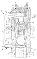
- Fig. 1 is a hydraulic cylinder generally designated 1 in Shown a plunger cylinder, the one in a cylinder housing 2 between a cylinder base 3 and a cylinder head 4 displaceable piston rod 5 (arrow K ', Fig. 1).
- This in an interior 6 of the cylinder housing 2 displaceable piston rod 5 is in turn sleeve-shaped and has in its interior 7 in the area of the annular working piston 8 entering threaded spindle 11 by means of a trapezoid thread 10 in the area of a threaded connection effective in the manner of a spindle nut 9 is rotatably supported.
- the threaded spindle is in its longitudinal extension towards the area of the cylinder base 3 11 supported by a bearing assembly, generally designated 12, in the area of which stop the rotary movement according to arrow direction A.
- Locking unit 13 is provided.
- This locking unit has an axially slidably connected to the threaded spindle 11 connecting member 14 on that in the area of a rotationally fixed at the front end in the interior E of the cylinder bottom 3 held counter member 15 can be braked.
- the connecting member 14 by means of a compression spring 16 in the connecting position (Fig. 2) relocatable (arrow F) and the connecting member 14 through a pushing body 17 displaceable against the spring action can be unlocked is (arrow S).
- FIG. 3 is an enlarged schematic diagram of the structure according to the invention the locking unit 13 similar to FIG. 2 shown. It becomes clear that the connecting member 14 as a with the compression spring 16 on a support attachment part 19 of the threaded spindle 11 formed axially displaceable locking piston 20 is.
- This locking piston 20 is at the front end of the cylinder bottom 3 facing end face provided with a toothing profile 21, which can be snapped into counter-teeth 22 on the bottom (FIG. 4).
- This toothing profiles 21, 22 form with a coaxial to this Locking piston 20 centrally receiving support bearing 23 and interacting with it Thrust body 17 is a functional unit with which one in almost Infinitely accessible stroke positions of the working piston 8 switchable Locking is possible, which is simple and reliable Component design.
- the locking piston 20 and one on the back Actuator 24 having thrust bodies 17 form in the region of the support bearing 23 a connection unit, such that the slidable on the support extension part 19 Locking piston 20 by means of the support bearing 23 in the exact position Counter toothing 22 can be locked and disengaged.
- the locking piston 20 each with an outer ring 25 of a roller bearing Support bearing 23 connected and this detects with its inner ring 26 the Thrust body 17. It is also conceivable that the locking piston 20 as the central Support bearing 23 cooperates with a plain bearing (not shown).
- the locking piston is 20 in the area of the locking unit 13 with two opposite one another an unlockable connection in the manner of a Hirth serration and in the sectional view, only in principle visible ring gears 30, 31 (Fig. 4) provided, which can be applied to the locking piston 20 during unlocking Thrust body 17 is guided centrally into the working pressure chamber 28.
- the locking piston 20 has a toothing profile a helical spur gear profile 32, which in the internal gear 33 can be inserted into the cylinder base 3 (connection position: FIG. 7).
- 6 shows the schematic representation of this locking assembly 13 'a recessed receiving contour 28 'into the support bearing 23 corresponding to the contour 28 in FIG. 3 immersed in the blocking position of the profiles 32 and 33.
- the interacting with the locking piston 20, 20 'thrust body 17 has in Area of the through bore D provided in the cylinder base 3 Sealing ring 34 'and a guide ring 34, which is a central guide part 35 of the thrust body 17 embrace.
- the thrust body 17 is included a pressure piston 36 is received in an outer pressure chamber 37, so that the thrust body 17 by means of the pressure piston 36 on the outside with a control pressure (Pressure port 38) can be acted upon and thus the actuator 24 is effective becomes.
- the construction of the locking unit 13 is in the area of the thrust body 17 3, 4 and 6 shown with one-piece cylinder base 3.
- Execution (Fig. 1, 2 and 7) is the working pressure chamber 28 with one of the thrust body 17 penetrated in the area of the through hole D, front Locking sleeve 39 is closed, the radially expanded and outside has a pressure chamber 37 closed by a cover part 40.
- the pressure chamber 37 can be pressurized with fluid pressure (arrow P) formed in particular in one piece with the thrust body 17, also one Execution with screwed individual parts is conceivable (not shown).
- the seals 41 and 34 'in the area of the thrust body 17 are in the Adjustment movements of the thrust body 17 are only slightly loaded because of the switching paths are short and no rotary seals are used.
- the thrust body 17 acts in the area of the pressure piston 36 with a front at 37 'in the Pressure space 37 opening vent hole 42 together (Fig. 3).
- in the The area of its pressure piston 36 has a thrust body 17 at a distance R to the central longitudinal plane M extending retaining pin 49 on the one hand in the cover part 40 is held and on the other hand axially displaceable in a bore 50 of the Pressure piston 36 engages. This prevents the thrust body 17 from rotating.
- the locking piston 20 is on the support attachment part 19 held by a spline 43 so that an optimal axial displacement in the direction of the central longitudinal axis M is possible. At the same time, this can Profiling the respective torques effective in the locking position optimal take up.
- the application is also a tongue and groove connection 44 (FIG. 1) is conceivable.
- the Locking piston 20, 20 'with a position sensor which detects its range of motion 45 interacts.
- the position sensor 45 is in the Cylinder base 3 engaging transducer 45 'provided by a close this displaceable contour formation 46 and an annular recess 46 'on the locking piston 20 whose respective position and thus the switching position of the lock is detected.
- the threaded spindle 11 with its angular position detecting sensor (not shown) cooperates so that a Distance measurement of the respective stroke position of the piston rod 5 is possible.
- the supporting attachment part is 19 in the area of its in front of the engaging pistons 20, 20 ' Compression spring 16 with two thrust bearings 47, 48 (Fig. 1, 2, 5 and 7) in the working pressure chamber E of the cylinder base 3 is supported so that the locking structure overall, a largely axial play-free and smooth construction is guaranteed.
- the locking described above in the area of the locking piston 20, 20 ' is as axially switchable unit can be used with a fine level.
- a shift are 5 respective lifting heights on the extending or retracting piston rod less than 0.5 mm realizable and after reaching the respective Position, stable locking and locking is possible.
- the front Tooth profile 30, 31; 32, 33 in particular with oblique flanks trained so that the switchability of the system is improved and a Automatic self-centering, especially with the shepherd's teeth, which are known per se is achieved.
- This construction of the hydraulic cylinder 1 is particularly in lifting devices can be used as a securing and / or holding device, so that, for example for a failure of the device during operation of the device Drive hydraulics a reliable backup is guaranteed or approached Stroke positions can be held securely.
- the constructive design of the thrust body provided with the pressure reinforcement in area B to C. 17 can avoid interference from the working hydraulics and overall the security of the system can be improved, this in the area of guided by the front bearing assembly 12 and the support bearing 23 Locking piston 20 has a long-term stable locking function.
- FIG. 8 shows a further embodiment of the working cylinder 1 ', whose construction corresponds essentially to that in Fig. 3, so that the corresponding reference numerals of the individual parts even without repeated Result in registration.
- the hydraulic cylinder 1 ' is with a locking unit 13 'provided, which in place of the toothing profiles 21, 22 (Fig. 3) in the area of a locking piston 20 "with a friction brake 51st is provided, the friction element (s) are shown in a braking position and thus ensure the locking function described above.
Landscapes
- Engineering & Computer Science (AREA)
- Physics & Mathematics (AREA)
- Fluid Mechanics (AREA)
- Mechanical Engineering (AREA)
- General Engineering & Computer Science (AREA)
- Actuator (AREA)
- Braking Arrangements (AREA)
Applications Claiming Priority (2)
| Application Number | Priority Date | Filing Date | Title |
|---|---|---|---|
| DE20216197U DE20216197U1 (de) | 2002-10-22 | 2002-10-22 | Hydraulischer Arbeitszylinder |
| DE20216197U | 2002-10-22 |
Publications (2)
| Publication Number | Publication Date |
|---|---|
| EP1420171A2 true EP1420171A2 (fr) | 2004-05-19 |
| EP1420171A3 EP1420171A3 (fr) | 2004-05-26 |
Family
ID=31984545
Family Applications (1)
| Application Number | Title | Priority Date | Filing Date |
|---|---|---|---|
| EP03019422A Withdrawn EP1420171A3 (fr) | 2002-10-22 | 2003-08-28 | Vérin hydraulique |
Country Status (2)
| Country | Link |
|---|---|
| EP (1) | EP1420171A3 (fr) |
| DE (1) | DE20216197U1 (fr) |
Cited By (9)
| Publication number | Priority date | Publication date | Assignee | Title |
|---|---|---|---|---|
| CN102943784A (zh) * | 2012-11-19 | 2013-02-27 | 湖南特力液压有限公司 | 缸筒、液压缸及包含该液压缸的泵送设备 |
| WO2018069128A1 (fr) * | 2016-10-10 | 2018-04-19 | Fbr Facondrehteile Gmbh | Vérin de blocage hydromécanique et système de commande hydraulique pour l'actionner |
| CN109630501A (zh) * | 2019-01-02 | 2019-04-16 | 中船重工中南装备有限责任公司 | 一种双向机械自锁的液压缸 |
| CN111532422A (zh) * | 2020-04-17 | 2020-08-14 | 贵州新安航空机械有限责任公司 | 一种直升机前机轮双向液压锁定机构 |
| CN111649025A (zh) * | 2020-06-30 | 2020-09-11 | 中国长江三峡集团有限公司 | 一种自动锁定液压启闭机油缸装置及其控制方法 |
| CN113404741A (zh) * | 2021-06-28 | 2021-09-17 | 徐州重型机械有限公司 | 驱动缸、车辆转向系统和车辆 |
| CN115539459A (zh) * | 2022-11-29 | 2022-12-30 | 恒宏智能装备有限公司 | 一种可任意位置锁定的液压缸及控制方法 |
| CN115842441A (zh) * | 2022-12-25 | 2023-03-24 | 四川凌峰航空液压机械有限公司 | 机电作动器真实到位锁定信号触发机构 |
| CN118815782A (zh) * | 2024-08-07 | 2024-10-22 | 山东益诚液压设备有限公司 | 一种超大吨位组合式任意位置自锁油缸 |
Families Citing this family (2)
| Publication number | Priority date | Publication date | Assignee | Title |
|---|---|---|---|---|
| DE102004022203B3 (de) * | 2004-05-05 | 2005-08-11 | Neumeister Hydraulik Gmbh | Verriegelungszylinder mit Gewinde-Freilauf |
| DE102005015059A1 (de) | 2005-03-31 | 2006-10-05 | Aros Hydraulik Gmbh | Verriegelbarer Arbeitszylinder |
Family Cites Families (13)
| Publication number | Priority date | Publication date | Assignee | Title |
|---|---|---|---|---|
| GB725003A (en) * | 1952-03-27 | 1955-03-02 | Gen Motors Corp | Improved fluid-pressure actuator |
| US2804053A (en) * | 1954-04-14 | 1957-08-27 | Gen Motors Corp | Actuator and locking means therefor |
| US2773485A (en) * | 1954-09-09 | 1956-12-11 | Gen Motors Corp | Self-locking actuator |
| US2879746A (en) * | 1955-12-08 | 1959-03-31 | Gen Motors Corp | Actuator with unidirectional locking means |
| US3472124A (en) * | 1967-09-08 | 1969-10-14 | Ellcon Nat | Braking apparatus |
| CH546895A (de) * | 1971-10-21 | 1974-03-15 | Bieri H Ag | Doppelwirkendes hydraulisches kolben- zylinderaggregat mit ruecklaufsperre. |
| DE2203473C2 (de) * | 1972-01-26 | 1983-07-07 | Pneumo Dynamics Corp., Cleveland, Ohio | Betätigungsvorrichtung für lineare Bewegungen mit Kolbenverriegelung |
| US4083436A (en) * | 1976-04-12 | 1978-04-11 | Abex Corporation | Brake apparatus including locking means therefor |
| JPS5367074A (en) * | 1976-11-29 | 1978-06-15 | Toyo Kohan Co Ltd | Air cylinder with brake |
| DE3713589A1 (de) * | 1987-04-23 | 1988-11-03 | Feinmechanische Geraete Irene | Einrichtung zum ruckfreien abbremsen und zur positionierung von luft-, fluessigkeit-, elektrisch betaetigten linear zylindern |
| EP0322503A3 (fr) * | 1987-12-29 | 1991-09-25 | Daihatsu Diesel Mfg. Co., Ltd. | Appareil à fluide |
| DE3807669A1 (de) * | 1988-03-09 | 1989-09-21 | Andexser Lucie | Stufenlos verriegelbarer arbeitszylinder |
| DE20011789U1 (de) * | 2000-07-06 | 2000-12-21 | Bümach Engineering International B.V., Emmen | Druckmittelbetriebener Arbeitszylinder mit mechanischer Wegsperrung im drucklosen Zustand |
-
2002
- 2002-10-22 DE DE20216197U patent/DE20216197U1/de not_active Expired - Lifetime
-
2003
- 2003-08-28 EP EP03019422A patent/EP1420171A3/fr not_active Withdrawn
Cited By (12)
| Publication number | Priority date | Publication date | Assignee | Title |
|---|---|---|---|---|
| CN102943784A (zh) * | 2012-11-19 | 2013-02-27 | 湖南特力液压有限公司 | 缸筒、液压缸及包含该液压缸的泵送设备 |
| CN102943784B (zh) * | 2012-11-19 | 2015-06-10 | 湖南特力液压有限公司 | 缸筒、液压缸及包含该液压缸的泵送设备 |
| WO2018069128A1 (fr) * | 2016-10-10 | 2018-04-19 | Fbr Facondrehteile Gmbh | Vérin de blocage hydromécanique et système de commande hydraulique pour l'actionner |
| CN109630501A (zh) * | 2019-01-02 | 2019-04-16 | 中船重工中南装备有限责任公司 | 一种双向机械自锁的液压缸 |
| CN109630501B (zh) * | 2019-01-02 | 2023-12-01 | 中船重工中南装备有限责任公司 | 一种双向机械自锁的液压缸 |
| CN111532422A (zh) * | 2020-04-17 | 2020-08-14 | 贵州新安航空机械有限责任公司 | 一种直升机前机轮双向液压锁定机构 |
| CN111649025A (zh) * | 2020-06-30 | 2020-09-11 | 中国长江三峡集团有限公司 | 一种自动锁定液压启闭机油缸装置及其控制方法 |
| CN111649025B (zh) * | 2020-06-30 | 2024-06-07 | 中国长江三峡集团有限公司 | 一种自动锁定液压启闭机油缸装置及其控制方法 |
| CN113404741A (zh) * | 2021-06-28 | 2021-09-17 | 徐州重型机械有限公司 | 驱动缸、车辆转向系统和车辆 |
| CN115539459A (zh) * | 2022-11-29 | 2022-12-30 | 恒宏智能装备有限公司 | 一种可任意位置锁定的液压缸及控制方法 |
| CN115842441A (zh) * | 2022-12-25 | 2023-03-24 | 四川凌峰航空液压机械有限公司 | 机电作动器真实到位锁定信号触发机构 |
| CN118815782A (zh) * | 2024-08-07 | 2024-10-22 | 山东益诚液压设备有限公司 | 一种超大吨位组合式任意位置自锁油缸 |
Also Published As
| Publication number | Publication date |
|---|---|
| EP1420171A3 (fr) | 2004-05-26 |
| DE20216197U1 (de) | 2004-03-04 |
Similar Documents
| Publication | Publication Date | Title |
|---|---|---|
| EP0544851B1 (fr) | Dispositif de rattrapage de jeu commande par pression pour un frein de vehicule | |
| DE20118907U1 (de) | Parksperre und Wälzlageraußenring für eine solche | |
| AT517492B1 (de) | Längenverstellbare pleuelstange | |
| DE4239070C2 (de) | Anordnung aus einem Hydromotor und einer Bremse | |
| EP1420171A2 (fr) | Vérin hydraulique | |
| EP1995471B1 (fr) | Cylindre verrouillable à palier fluidique | |
| AT522077B1 (de) | Längenverstellbare Pleuelstange mit Stützringmutter | |
| DE19922333A1 (de) | Scheibenbremse mit Feststellbremsfunktion | |
| DE4311855A1 (de) | Stellantriebssystem für Schaltgetriebe von Kraftfahrzeugen | |
| AT517112A4 (de) | Längenverstellbare pleuelstange | |
| DE102014226611A1 (de) | Klauenkupplung | |
| EP3344881B1 (fr) | Vérin de blocage hydromécanique et système de commande hydraulique pour l'actionner | |
| DE102008038439B3 (de) | Bistabile Betätigungsvorrichtung für ein Ventil | |
| EP3073127B1 (fr) | Composant piston-cylindre pour verin a pression, verin a pression et boite de transfert | |
| EP1170512B1 (fr) | Vérin à fluide sous pression avec verrouillage mécanique lorsque non pressurisé | |
| AT505793A1 (de) | Zylinder-kolben-einheit mit sperranordnung | |
| DE102016215281A1 (de) | Längenverstellbare Pleuelstange | |
| DE4417959C2 (de) | Vorrichtung zum Verändern der Steuerzeiten einer Brennkraftmaschine | |
| AT524662A4 (de) | Längenverstellbare Pleuelstange mit Schraubbund | |
| EP1538344A2 (fr) | Vérin verrouillable | |
| AT519294A2 (de) | Längenverstellbare Pleuelstange mit einer Zylinder-Kolben-Einheit mit Zylinderhülse | |
| DE10006349C2 (de) | Vorrichtung zur relativen Winkelverstellung einer Nockenwelle | |
| EP1538343A2 (fr) | Vérin verrouillable | |
| DE19709736C1 (de) | Absperrventil, insbesondere Kurzhubventil | |
| DE102006042478A1 (de) | Elektromotorischer Aktuator zur Auslenkung eines mechanischen Teils |
Legal Events
| Date | Code | Title | Description |
|---|---|---|---|
| PUAI | Public reference made under article 153(3) epc to a published international application that has entered the european phase |
Free format text: ORIGINAL CODE: 0009012 |
|
| PUAL | Search report despatched |
Free format text: ORIGINAL CODE: 0009013 |
|
| AK | Designated contracting states |
Kind code of ref document: A2 Designated state(s): AT BE BG CH CY CZ DE DK EE ES FI FR GB GR HU IE IT LI LU MC NL PT RO SE SI SK TR |
|
| AX | Request for extension of the european patent |
Extension state: AL LT LV MK |
|
| AK | Designated contracting states |
Kind code of ref document: A3 Designated state(s): AT BE BG CH CY CZ DE DK EE ES FI FR GB GR HU IE IT LI LU MC NL PT RO SE SI SK TR |
|
| AX | Request for extension of the european patent |
Extension state: AL LT LV MK |
|
| AKX | Designation fees paid | ||
| REG | Reference to a national code |
Ref country code: DE Ref legal event code: 8566 |
|
| STAA | Information on the status of an ep patent application or granted ep patent |
Free format text: STATUS: THE APPLICATION IS DEEMED TO BE WITHDRAWN |
|
| 18D | Application deemed to be withdrawn |
Effective date: 20041127 |