EP1420178B1 - Joint d'une articulation à rotule chez le côté du pivot sphérique - Google Patents
Joint d'une articulation à rotule chez le côté du pivot sphérique Download PDFInfo
- Publication number
- EP1420178B1 EP1420178B1 EP03026094A EP03026094A EP1420178B1 EP 1420178 B1 EP1420178 B1 EP 1420178B1 EP 03026094 A EP03026094 A EP 03026094A EP 03026094 A EP03026094 A EP 03026094A EP 1420178 B1 EP1420178 B1 EP 1420178B1
- Authority
- EP
- European Patent Office
- Prior art keywords
- sealing
- ball
- leg
- spherical
- sealing bellows
- Prior art date
- Legal status (The legal status is an assumption and is not a legal conclusion. Google has not performed a legal analysis and makes no representation as to the accuracy of the status listed.)
- Expired - Lifetime
Links
- 238000007789 sealing Methods 0.000 title claims abstract description 51
- 241001125877 Gobio gobio Species 0.000 title 1
- 230000000284 resting effect Effects 0.000 claims description 4
- 229910001220 stainless steel Inorganic materials 0.000 claims description 2
- 239000010935 stainless steel Substances 0.000 claims description 2
- 241001125879 Gobio Species 0.000 claims 11
- 238000005096 rolling process Methods 0.000 description 7
- 238000011109 contamination Methods 0.000 description 1
- 238000006073 displacement reaction Methods 0.000 description 1
- 125000006850 spacer group Chemical group 0.000 description 1
Images

Classifications
-
- F—MECHANICAL ENGINEERING; LIGHTING; HEATING; WEAPONS; BLASTING
- F16—ENGINEERING ELEMENTS AND UNITS; GENERAL MEASURES FOR PRODUCING AND MAINTAINING EFFECTIVE FUNCTIONING OF MACHINES OR INSTALLATIONS; THERMAL INSULATION IN GENERAL
- F16C—SHAFTS; FLEXIBLE SHAFTS; ELEMENTS OR CRANKSHAFT MECHANISMS; ROTARY BODIES OTHER THAN GEARING ELEMENTS; BEARINGS
- F16C11/00—Pivots; Pivotal connections
- F16C11/04—Pivotal connections
- F16C11/06—Ball-joints; Other joints having more than one degree of angular freedom, i.e. universal joints
- F16C11/0666—Sealing means between the socket and the inner member shaft
- F16C11/0671—Sealing means between the socket and the inner member shaft allowing operative relative movement of joint parts due to flexing of the sealing means
-
- F—MECHANICAL ENGINEERING; LIGHTING; HEATING; WEAPONS; BLASTING
- F16—ENGINEERING ELEMENTS AND UNITS; GENERAL MEASURES FOR PRODUCING AND MAINTAINING EFFECTIVE FUNCTIONING OF MACHINES OR INSTALLATIONS; THERMAL INSULATION IN GENERAL
- F16C—SHAFTS; FLEXIBLE SHAFTS; ELEMENTS OR CRANKSHAFT MECHANISMS; ROTARY BODIES OTHER THAN GEARING ELEMENTS; BEARINGS
- F16C11/00—Pivots; Pivotal connections
- F16C11/04—Pivotal connections
- F16C11/06—Ball-joints; Other joints having more than one degree of angular freedom, i.e. universal joints
- F16C11/0619—Ball-joints; Other joints having more than one degree of angular freedom, i.e. universal joints the female part comprising a blind socket receiving the male part
Definitions
- the invention relates to a ball-pin-side sealing a ball joint according to the preamble of the first protection claim.
- Numerous ball joints are known, which have a housing provided with a cavity, in which the ball of a ball stud is movably mounted in a bearing shell (DE 197 55 248 A1, DE 197 50 830 A1, DE 196 25 351 C1).
- the sealing takes place both on the housing side and ball journal side via a sealing bellows.
- the sealing bellows is usually attached to the housing and the outer diameter of the pin via retaining rings. In the connection between sealing bellows and ball studs leaks are often recorded, which can lead to contamination of the ball joint and thus to increased wear and failure.
- An already improved Abdicht variant between ball stud and sealing bellows is described in DE 197 47 931 C1.
- the ball pin on an annular collar, through which an undercut is formed, in which the sealing bellows is used under axial bias.
- the sealing bellows is via clamping rings radially against its Investment areas pressed.
- a spacer is additionally arranged to prevent axial displacement of the sealing bellows in the direction of ball.
- the object of the invention is to provide a simple and reliable seal between a sealing bellows and the ball stud.
- the ball-pin-side seal for a ball joint which has a housing for receiving a movably mounted ball of a ball pin and a seal on the housing and the ball stud sealing bellows, the first sealing bellows edge on the shaft of the ball stud and the second sealing bellows edge adjacent to the housing, according to the invention at the shaft of the ball pin sealing first Dichtungsbalgrand provided at its upwardly open end with a radially encircling, outwardly directed leg which rests on its, the ball side facing away from a seated on the shaft disc, the disc and the first Dichtungsbaloffice means a cross-sectionally U-shaped profile ring are interconnected.
- the leg of the first sealing bellows edge and the disc are advantageously at least partially within a circumferential, arranged inwardly trough of the profile ring, which is formed by two inwardly directed radially encircling legs and a connecting both axial leg of the profile ring.
- the disc can rest with its pointing in the direction of the ball side to a stop of the shank of the ball stud.
- the leg which adjoins the leg of the first sealing bellows edge and / or the leg of the profiled ring adjacent to the disc is preferably a rolled edge formed by curling.
- the disc and / or the profile element consist in particular of stainless steel.
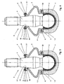
- Figures 1 to 4 show a schematic representation of a ball joint with a housing 1 for a ball pin K toward open receiving a movably mounted ball 2 of the ball pin K.
- a sealing bellows 3 is arranged, the sealing bellows edge D1 on the Shank 4 of the ball pin K sealingly abuts.
- the second sealing bellows edge D2 is sealingly connected to the housing 1.
- the first sealing bellows edge D1 which seals against the shank 4 of the ball stud K, has a radially encircling, outwardly directed limb 3.1 at its open end which, on its side facing away from the ball 2, is seated against a disc S seated on the shank 4 is applied.
- Fig. 1 shows a ball joint with profile ring P, whose gem.
- Fig. 2 is applied to the disc S adjacent leg P2 is rolled before rolling.
- the disc S rests with its pointing in the direction of the ball 2 side of a stop 4.1 of the shaft 4 of the ball stud K, wherein the stopper 4.1 is formed as a circumferential edge.
- the profile ring P rests with its inwardly directed first leg P1 on the leg 3.1 of the first Dichtungsbalage D1.
- At the radially inwardly directed leg P1 of the profile ring P adjoins the axial leg P3 and to this a still parallel to the axis A of the ball stud K extending portion B2 of the profile ring P.
- This area B2 of the profile ring P is curled in the direction of the shaft 4 of the ball stud K (arrow) over the slices S cross and now forms gem. 2 shows the second radially inwardly directed leg P2 of the profile ring P.
- the second leg P2 may already be bent inwards and after rolling up the first leg P1 forming region B1 of the profile ring P the disc S and the radially encircling, outwardly directed leg 3.1 of the first sealing portion D1 of the sealing bellows 3 in Overhanging the direction of the housing 1.
- This area B1 is then rolled in the direction of the arrow, the legs 3.1 cross-over, and it follows gem.
- Fig. 4 the attachment of the first sealing region D1 on the shaft 4 of the ball stud, which corresponds to that already shown in Fig. 2.
- the sealing area D2 has also been fastened to the housing 1 by rolling in a rolled edge 1.1. Between roll edge 1.1 of the housing 1 and sealing area D2 there is a disc-shaped sealing / securing element 6.
- This sealing / securing element 6 is designed and arranged such that a positive connection between sealing bellows edge D2, the sealing / securing element 6 and the housing 1 is present is.
Landscapes
- Engineering & Computer Science (AREA)
- General Engineering & Computer Science (AREA)
- Mechanical Engineering (AREA)
- Pivots And Pivotal Connections (AREA)
- Sealing Devices (AREA)
Claims (6)
- Joint d'étanchéité du goujon sphérique pour une articulation à rotule, comprenant un logement (1) destiné à recevoir une sphère (2) d'un goujon sphérique (K) supportée de manière mobile et un soufflet d'étanchéité (3) disposé entre le logement (1) et le goujon sphérique (K), dont le premier bord de soufflet d'étanchéité (D1) repose de manière étanche sur la tige (4) du goujon sphérique (K) et le second bord de soufflet d'étanchéité (D2) sur le logement (1), caractérisé en ce que le premier bord de soufflet d'étanchéité (D1) assurant l'étanchéité sur la tige (4) du goujon sphérique (K) possède à son extrémité ouverte vers le haut un bras (3.1) continu dans le sens radial et orienté vers l'extérieur, qui repose de son côté opposé à la sphère (2) sur un disque (S) reposant sur la tige (4) et en ce que le disque (S) et le premier bord de soufflet d'étanchéité (D1) sont reliés entre eux par l'intermédiaire d'une bague profilée (P) ayant une forme de U en section.
- Joint d'étanchéité du goujon sphérique selon la revendication 1, caractérisé en ce que le bras (3.1) du premier bord de soufflet d'étanchéité (D1) et le disque (S) sont disposés au moins en partie à l'intérieur d'une auge de la bague profilée (P) continue et ouverte vers l'intérieur, qui est formée par deux bras (P1, P2) orientés vers l'intérieur et continus dans le sens radial et un bras axial (P3) de la bague profilée (P) reliant ceux-ci.
- Joint d'étanchéité du goujon sphérique selon la revendication 1 ou 2, caractérisé en ce que le disque (S) repose, par son côté orienté en direction de la sphère (2), sur une butée (4.1) du corps (4) du goujon sphérique (K).
- Joint d'étanchéité du goujon sphérique selon la revendication 3, caractérisé en ce que la butée (4.1) du corps (4) est conformée comme un bord continu.
- Joint d'étanchéité du goujon sphérique selon l'une quelconque des revendications 1 à 4, caractérisé en ce que le bras (P1) reposant sur le bras (3.1) du premier bord de soufflet d'étanchéité (D1) et/ou le bras (P2) de la bague profilée (P) reposant sur le disque (S) sont un bord roulé mis en forme par enroulement.
- Joint d'étanchéité du goujon sphérique selon l'une quelconque des revendications 1 à 5, caractérisé en ce que le disque (S) et/ou l'élément profilé (P) se composent d'acier inoxydable.
Applications Claiming Priority (2)
| Application Number | Priority Date | Filing Date | Title |
|---|---|---|---|
| DE20217685U DE20217685U1 (de) | 2002-11-14 | 2002-11-14 | Kugelzapfenseitige Abdichtung eines Kugelgelenks |
| DE20217685U | 2002-11-14 |
Publications (3)
| Publication Number | Publication Date |
|---|---|
| EP1420178A2 EP1420178A2 (fr) | 2004-05-19 |
| EP1420178A3 EP1420178A3 (fr) | 2005-06-15 |
| EP1420178B1 true EP1420178B1 (fr) | 2006-02-08 |
Family
ID=32038864
Family Applications (1)
| Application Number | Title | Priority Date | Filing Date |
|---|---|---|---|
| EP03026094A Expired - Lifetime EP1420178B1 (fr) | 2002-11-14 | 2003-11-13 | Joint d'une articulation à rotule chez le côté du pivot sphérique |
Country Status (3)
| Country | Link |
|---|---|
| EP (1) | EP1420178B1 (fr) |
| AT (1) | ATE317504T1 (fr) |
| DE (2) | DE20217685U1 (fr) |
Families Citing this family (3)
| Publication number | Priority date | Publication date | Assignee | Title |
|---|---|---|---|---|
| CN106828599B (zh) * | 2016-12-19 | 2019-09-27 | 涡阳县安元汽车配件有限公司 | 一种具有多重密封结构的转向器外球头组件 |
| RU2730763C1 (ru) | 2017-08-16 | 2020-08-26 | Малтиматик Инк. | Шаровой шарнир с вкладышем, полученным методом инжекционного формования |
| US11713783B2 (en) | 2021-07-23 | 2023-08-01 | Federal-Mogul Motorparts Llc | Grease boot for a ball joint |
Family Cites Families (6)
| Publication number | Priority date | Publication date | Assignee | Title |
|---|---|---|---|---|
| US2397464A (en) * | 1943-10-30 | 1946-04-02 | Thompson Prod Inc | Seal structure |
| GB1077149A (en) * | 1965-05-25 | 1967-07-26 | Automotive Prod Co Ltd | Improvements in or relating to sealing boots for ball-and-socket joint assemblies |
| DE1525083B1 (de) * | 1965-11-20 | 1970-07-30 | Ehrenreich & Cie A | Elastische Dichtung in Balgform fuer allseitig bewegliche Gelenke,insbesondere Kugelgelenke |
| FR1538231A (fr) * | 1966-10-08 | 1968-08-30 | Ehrenreich & Cie A | Articulation à rotule, notamment pour véhicules à moteurs |
| JPS5839214Y2 (ja) * | 1978-05-16 | 1983-09-05 | トヨタ自動車株式会社 | サスペンシヨンボ−ルジヨイント取付部構造 |
| DE19950281B4 (de) * | 1999-10-19 | 2004-02-05 | Sachsenring Fahrzeugtechnik Gmbh | Kugelgelenk |
-
2002
- 2002-11-14 DE DE20217685U patent/DE20217685U1/de not_active Expired - Lifetime
-
2003
- 2003-11-13 DE DE50302375T patent/DE50302375D1/de not_active Expired - Fee Related
- 2003-11-13 AT AT03026094T patent/ATE317504T1/de not_active IP Right Cessation
- 2003-11-13 EP EP03026094A patent/EP1420178B1/fr not_active Expired - Lifetime
Also Published As
| Publication number | Publication date |
|---|---|
| EP1420178A2 (fr) | 2004-05-19 |
| ATE317504T1 (de) | 2006-02-15 |
| EP1420178A3 (fr) | 2005-06-15 |
| DE50302375D1 (de) | 2006-04-20 |
| DE20217685U1 (de) | 2004-03-18 |
Similar Documents
| Publication | Publication Date | Title |
|---|---|---|
| DE60037440T2 (de) | Vorrichtung zum verbinden rohrförmiger körper | |
| EP1859189A1 (fr) | Raccord a serrage pour un tuyau sanitaire et/ou de chauffage | |
| DE2731464A1 (de) | Rohrkupplung | |
| EP0213364B1 (fr) | Raccord à brides | |
| WO2000025080A1 (fr) | Raccord de tuyauterie entre un collecteur de l'echangeur thermique d'un vehicule automobile et une conduite exterieure | |
| CH664814A5 (de) | Muffenverbindung. | |
| DE69931773T2 (de) | Rohrverbindung | |
| EP3385506B1 (fr) | Agencement d'étanchéité pour turbine à gaz | |
| EP1222407B1 (fr) | Joint a rotule | |
| DE102010060844B4 (de) | Dichtungselement für ein Gleichlaufdrehgelenk und Gleichlaufdrehgelenkanordnung | |
| DD286026A5 (de) | Zylinderkopf-brennraumabdichtung fuer einen hubkolbenmotor | |
| WO2009152814A1 (fr) | Joint plat | |
| DE7008244U (de) | Drehklappenventil. | |
| EP3781855A1 (fr) | Collier de serrage | |
| DE69703856T2 (de) | Kupplung für zwei Metallrohre | |
| EP3397889B1 (fr) | Dispositif de raccordement | |
| DE102015216324A1 (de) | Verbindungsanordnung für Wellrohrschlauchleitungen | |
| EP1420178A2 (fr) | Joint d'une articulation à rotule chez le côté du pivot sphérique | |
| EP0879377B1 (fr) | Raccord amovible pour tuyaux en plastique | |
| WO2007012396A1 (fr) | Rotule et garniture cylindrique destinee a une rotule de ce type | |
| DE3919765C2 (fr) | ||
| EP1416175A2 (fr) | Dispositif d'étanchéité pour une articulation à rotule | |
| DE102018000700A1 (de) | Dichtring | |
| DE102010015352B4 (de) | Balg, Welle mit Balg und Verfahren zur Montage eines Balges auf einer Welle | |
| DE4315958A1 (de) | Rohrdichtung |
Legal Events
| Date | Code | Title | Description |
|---|---|---|---|
| PUAI | Public reference made under article 153(3) epc to a published international application that has entered the european phase |
Free format text: ORIGINAL CODE: 0009012 |
|
| AK | Designated contracting states |
Kind code of ref document: A2 Designated state(s): AT BE BG CH CY CZ DE DK EE ES FI FR GB GR HU IE IT LI LU MC NL PT RO SE SI SK TR |
|
| AX | Request for extension of the european patent |
Extension state: AL LT LV MK |
|
| RAP1 | Party data changed (applicant data changed or rights of an application transferred) |
Owner name: SACHSENRING ZWICKAU AG |
|
| PUAL | Search report despatched |
Free format text: ORIGINAL CODE: 0009013 |
|
| AK | Designated contracting states |
Kind code of ref document: A3 Designated state(s): AT BE BG CH CY CZ DE DK EE ES FI FR GB GR HU IE IT LI LU MC NL PT RO SE SI SK TR |
|
| AX | Request for extension of the european patent |
Extension state: AL LT LV MK |
|
| GRAP | Despatch of communication of intention to grant a patent |
Free format text: ORIGINAL CODE: EPIDOSNIGR1 |
|
| 17P | Request for examination filed |
Effective date: 20050722 |
|
| RTI1 | Title (correction) |
Free format text: SEALING OF A BALL JOINT ON THE SIDE OF ITS SPHERICAL GUDGEON |
|
| GRAS | Grant fee paid |
Free format text: ORIGINAL CODE: EPIDOSNIGR3 |
|
| GRAA | (expected) grant |
Free format text: ORIGINAL CODE: 0009210 |
|
| AK | Designated contracting states |
Kind code of ref document: B1 Designated state(s): AT BE BG CH CY CZ DE DK EE ES FI FR GB GR HU IE IT LI LU MC NL PT RO SE SI SK TR |
|
| PG25 | Lapsed in a contracting state [announced via postgrant information from national office to epo] |
Ref country code: IE Free format text: LAPSE BECAUSE OF FAILURE TO SUBMIT A TRANSLATION OF THE DESCRIPTION OR TO PAY THE FEE WITHIN THE PRESCRIBED TIME-LIMIT Effective date: 20060208 Ref country code: IT Free format text: LAPSE BECAUSE OF FAILURE TO SUBMIT A TRANSLATION OF THE DESCRIPTION OR TO PAY THE FEE WITHIN THE PRESCRIBED TIME-LIMIT;WARNING: LAPSES OF ITALIAN PATENTS WITH EFFECTIVE DATE BEFORE 2007 MAY HAVE OCCURRED AT ANY TIME BEFORE 2007. THE CORRECT EFFECTIVE DATE MAY BE DIFFERENT FROM THE ONE RECORDED. Effective date: 20060208 Ref country code: NL Free format text: LAPSE BECAUSE OF FAILURE TO SUBMIT A TRANSLATION OF THE DESCRIPTION OR TO PAY THE FEE WITHIN THE PRESCRIBED TIME-LIMIT Effective date: 20060208 Ref country code: SI Free format text: LAPSE BECAUSE OF FAILURE TO SUBMIT A TRANSLATION OF THE DESCRIPTION OR TO PAY THE FEE WITHIN THE PRESCRIBED TIME-LIMIT Effective date: 20060208 Ref country code: RO Free format text: LAPSE BECAUSE OF FAILURE TO SUBMIT A TRANSLATION OF THE DESCRIPTION OR TO PAY THE FEE WITHIN THE PRESCRIBED TIME-LIMIT Effective date: 20060208 Ref country code: FI Free format text: LAPSE BECAUSE OF FAILURE TO SUBMIT A TRANSLATION OF THE DESCRIPTION OR TO PAY THE FEE WITHIN THE PRESCRIBED TIME-LIMIT Effective date: 20060208 Ref country code: GB Free format text: LAPSE BECAUSE OF FAILURE TO SUBMIT A TRANSLATION OF THE DESCRIPTION OR TO PAY THE FEE WITHIN THE PRESCRIBED TIME-LIMIT Effective date: 20060208 Ref country code: SK Free format text: LAPSE BECAUSE OF FAILURE TO SUBMIT A TRANSLATION OF THE DESCRIPTION OR TO PAY THE FEE WITHIN THE PRESCRIBED TIME-LIMIT Effective date: 20060208 |
|
| REG | Reference to a national code |
Ref country code: GB Ref legal event code: FG4D Free format text: NOT ENGLISH |
|
| REG | Reference to a national code |
Ref country code: CH Ref legal event code: EP |
|
| AKX | Designation fees paid |
Designated state(s): AT BE BG CH CY CZ DE DK EE ES FI FR GB GR HU IE IT LI LU MC NL PT RO SE SI SK TR |
|
| REG | Reference to a national code |
Ref country code: IE Ref legal event code: FG4D Free format text: LANGUAGE OF EP DOCUMENT: GERMAN |
|
| REF | Corresponds to: |
Ref document number: 50302375 Country of ref document: DE Date of ref document: 20060420 Kind code of ref document: P |
|
| PG25 | Lapsed in a contracting state [announced via postgrant information from national office to epo] |
Ref country code: SE Free format text: LAPSE BECAUSE OF FAILURE TO SUBMIT A TRANSLATION OF THE DESCRIPTION OR TO PAY THE FEE WITHIN THE PRESCRIBED TIME-LIMIT Effective date: 20060508 Ref country code: DK Free format text: LAPSE BECAUSE OF FAILURE TO SUBMIT A TRANSLATION OF THE DESCRIPTION OR TO PAY THE FEE WITHIN THE PRESCRIBED TIME-LIMIT Effective date: 20060508 Ref country code: BG Free format text: LAPSE BECAUSE OF FAILURE TO SUBMIT A TRANSLATION OF THE DESCRIPTION OR TO PAY THE FEE WITHIN THE PRESCRIBED TIME-LIMIT Effective date: 20060508 |
|
| PG25 | Lapsed in a contracting state [announced via postgrant information from national office to epo] |
Ref country code: ES Free format text: LAPSE BECAUSE OF FAILURE TO SUBMIT A TRANSLATION OF THE DESCRIPTION OR TO PAY THE FEE WITHIN THE PRESCRIBED TIME-LIMIT Effective date: 20060519 |
|
| NLV1 | Nl: lapsed or annulled due to failure to fulfill the requirements of art. 29p and 29m of the patents act | ||
| PG25 | Lapsed in a contracting state [announced via postgrant information from national office to epo] |
Ref country code: PT Free format text: LAPSE BECAUSE OF FAILURE TO SUBMIT A TRANSLATION OF THE DESCRIPTION OR TO PAY THE FEE WITHIN THE PRESCRIBED TIME-LIMIT Effective date: 20060710 |
|
| GBV | Gb: ep patent (uk) treated as always having been void in accordance with gb section 77(7)/1977 [no translation filed] |
Effective date: 20060208 |
|
| REG | Reference to a national code |
Ref country code: IE Ref legal event code: FD4D |
|
| PGFP | Annual fee paid to national office [announced via postgrant information from national office to epo] |
Ref country code: DE Payment date: 20061020 Year of fee payment: 4 |
|
| PG25 | Lapsed in a contracting state [announced via postgrant information from national office to epo] |
Ref country code: BE Free format text: LAPSE BECAUSE OF NON-PAYMENT OF DUE FEES Effective date: 20061130 Ref country code: MC Free format text: LAPSE BECAUSE OF NON-PAYMENT OF DUE FEES Effective date: 20061130 |
|
| PLBE | No opposition filed within time limit |
Free format text: ORIGINAL CODE: 0009261 |
|
| STAA | Information on the status of an ep patent application or granted ep patent |
Free format text: STATUS: NO OPPOSITION FILED WITHIN TIME LIMIT |
|
| 26N | No opposition filed |
Effective date: 20061109 |
|
| EN | Fr: translation not filed | ||
| BERE | Be: lapsed |
Owner name: SACHSENRING ZWICKAU A.G. Effective date: 20061130 |
|
| PG25 | Lapsed in a contracting state [announced via postgrant information from national office to epo] |
Ref country code: AT Free format text: LAPSE BECAUSE OF NON-PAYMENT OF DUE FEES Effective date: 20061113 |
|
| PG25 | Lapsed in a contracting state [announced via postgrant information from national office to epo] |
Ref country code: CZ Free format text: LAPSE BECAUSE OF FAILURE TO SUBMIT A TRANSLATION OF THE DESCRIPTION OR TO PAY THE FEE WITHIN THE PRESCRIBED TIME-LIMIT Effective date: 20060208 Ref country code: FR Free format text: LAPSE BECAUSE OF FAILURE TO SUBMIT A TRANSLATION OF THE DESCRIPTION OR TO PAY THE FEE WITHIN THE PRESCRIBED TIME-LIMIT Effective date: 20070330 Ref country code: GR Free format text: LAPSE BECAUSE OF FAILURE TO SUBMIT A TRANSLATION OF THE DESCRIPTION OR TO PAY THE FEE WITHIN THE PRESCRIBED TIME-LIMIT Effective date: 20060509 |
|
| PG25 | Lapsed in a contracting state [announced via postgrant information from national office to epo] |
Ref country code: EE Free format text: LAPSE BECAUSE OF FAILURE TO SUBMIT A TRANSLATION OF THE DESCRIPTION OR TO PAY THE FEE WITHIN THE PRESCRIBED TIME-LIMIT Effective date: 20060208 |
|
| PG25 | Lapsed in a contracting state [announced via postgrant information from national office to epo] |
Ref country code: LI Free format text: LAPSE BECAUSE OF NON-PAYMENT OF DUE FEES Effective date: 20071130 Ref country code: CH Free format text: LAPSE BECAUSE OF NON-PAYMENT OF DUE FEES Effective date: 20071130 Ref country code: TR Free format text: LAPSE BECAUSE OF FAILURE TO SUBMIT A TRANSLATION OF THE DESCRIPTION OR TO PAY THE FEE WITHIN THE PRESCRIBED TIME-LIMIT Effective date: 20060208 Ref country code: LU Free format text: LAPSE BECAUSE OF NON-PAYMENT OF DUE FEES Effective date: 20061113 Ref country code: HU Free format text: LAPSE BECAUSE OF FAILURE TO SUBMIT A TRANSLATION OF THE DESCRIPTION OR TO PAY THE FEE WITHIN THE PRESCRIBED TIME-LIMIT Effective date: 20060809 |
|
| REG | Reference to a national code |
Ref country code: CH Ref legal event code: PL |
|
| PG25 | Lapsed in a contracting state [announced via postgrant information from national office to epo] |
Ref country code: DE Free format text: LAPSE BECAUSE OF NON-PAYMENT OF DUE FEES Effective date: 20080603 |
|
| PG25 | Lapsed in a contracting state [announced via postgrant information from national office to epo] |
Ref country code: FR Free format text: LAPSE BECAUSE OF FAILURE TO SUBMIT A TRANSLATION OF THE DESCRIPTION OR TO PAY THE FEE WITHIN THE PRESCRIBED TIME-LIMIT Effective date: 20060208 Ref country code: CY Free format text: LAPSE BECAUSE OF FAILURE TO SUBMIT A TRANSLATION OF THE DESCRIPTION OR TO PAY THE FEE WITHIN THE PRESCRIBED TIME-LIMIT Effective date: 20060208 |