EP1420239A2 - Erfassung und Identifikation von Fahrzeugen mit übermässigem Partikelgehalt im Abgas - Google Patents
Erfassung und Identifikation von Fahrzeugen mit übermässigem Partikelgehalt im Abgas Download PDFInfo
- Publication number
- EP1420239A2 EP1420239A2 EP03025764A EP03025764A EP1420239A2 EP 1420239 A2 EP1420239 A2 EP 1420239A2 EP 03025764 A EP03025764 A EP 03025764A EP 03025764 A EP03025764 A EP 03025764A EP 1420239 A2 EP1420239 A2 EP 1420239A2
- Authority
- EP
- European Patent Office
- Prior art keywords
- vehicle
- detection
- particulate
- station
- vehicles
- Prior art date
- Legal status (The legal status is an assumption and is not a legal conclusion. Google has not performed a legal analysis and makes no representation as to the accuracy of the status listed.)
- Withdrawn
Links
- 238000001514 detection method Methods 0.000 title claims abstract description 53
- 239000007789 gas Substances 0.000 title description 8
- 238000000034 method Methods 0.000 claims abstract description 27
- 239000000779 smoke Substances 0.000 claims description 27
- 238000003384 imaging method Methods 0.000 claims description 9
- 230000001960 triggered effect Effects 0.000 claims description 7
- 238000012545 processing Methods 0.000 claims description 6
- 238000012360 testing method Methods 0.000 description 22
- 238000012015 optical character recognition Methods 0.000 description 13
- 238000009434 installation Methods 0.000 description 8
- 230000008859 change Effects 0.000 description 4
- 238000012544 monitoring process Methods 0.000 description 4
- 230000009471 action Effects 0.000 description 3
- MWUXSHHQAYIFBG-UHFFFAOYSA-N nitrogen oxide Inorganic materials O=[N] MWUXSHHQAYIFBG-UHFFFAOYSA-N 0.000 description 3
- 230000003287 optical effect Effects 0.000 description 3
- 230000008569 process Effects 0.000 description 3
- CURLTUGMZLYLDI-UHFFFAOYSA-N Carbon dioxide Chemical compound O=C=O CURLTUGMZLYLDI-UHFFFAOYSA-N 0.000 description 2
- 230000004888 barrier function Effects 0.000 description 2
- 238000004364 calculation method Methods 0.000 description 2
- 230000007613 environmental effect Effects 0.000 description 2
- 239000003344 environmental pollutant Substances 0.000 description 2
- 238000011156 evaluation Methods 0.000 description 2
- 238000005259 measurement Methods 0.000 description 2
- 231100000719 pollutant Toxicity 0.000 description 2
- 230000004044 response Effects 0.000 description 2
- 238000012935 Averaging Methods 0.000 description 1
- RAHZWNYVWXNFOC-UHFFFAOYSA-N Sulphur dioxide Chemical class O=S=O RAHZWNYVWXNFOC-UHFFFAOYSA-N 0.000 description 1
- 238000010521 absorption reaction Methods 0.000 description 1
- 230000003213 activating effect Effects 0.000 description 1
- 230000000903 blocking effect Effects 0.000 description 1
- 239000001569 carbon dioxide Substances 0.000 description 1
- 229910002092 carbon dioxide Inorganic materials 0.000 description 1
- 238000004891 communication Methods 0.000 description 1
- 230000001276 controlling effect Effects 0.000 description 1
- 238000007599 discharging Methods 0.000 description 1
- 238000005516 engineering process Methods 0.000 description 1
- 230000036541 health Effects 0.000 description 1
- 238000005286 illumination Methods 0.000 description 1
- 230000003993 interaction Effects 0.000 description 1
- 230000007774 longterm Effects 0.000 description 1
- 238000004519 manufacturing process Methods 0.000 description 1
- 239000002184 metal Substances 0.000 description 1
- 229910052751 metal Inorganic materials 0.000 description 1
- 150000002739 metals Chemical class 0.000 description 1
- 238000012986 modification Methods 0.000 description 1
- 230000004048 modification Effects 0.000 description 1
- 230000005855 radiation Effects 0.000 description 1
- 230000001105 regulatory effect Effects 0.000 description 1
- 238000012552 review Methods 0.000 description 1
- 235000010269 sulphur dioxide Nutrition 0.000 description 1
- 238000012546 transfer Methods 0.000 description 1
- 239000012855 volatile organic compound Substances 0.000 description 1
- 230000036642 wellbeing Effects 0.000 description 1
Images
Classifications
-
- G—PHYSICS
- G08—SIGNALLING
- G08G—TRAFFIC CONTROL SYSTEMS
- G08G1/00—Traffic control systems for road vehicles
- G08G1/01—Detecting movement of traffic to be counted or controlled
- G08G1/017—Detecting movement of traffic to be counted or controlled identifying vehicles
- G08G1/0175—Detecting movement of traffic to be counted or controlled identifying vehicles by photographing vehicles, e.g. when violating traffic rules
Definitions
- the present invention relates to the detection of vehicles exceeding a predetermined level of particulate exhaust emissions.
- the invention has been developed primarily for detecting and identifying heavy vehicles having excess particulates in their exhaust gases and will be discussed hereinafter with reference to this application. However, it will be appreciated that the invention is not limited to this particular field of use.
- Gaseous and particulate emissions for example, sulphur dioxides, nitrogen oxides, metals, carbon dioxide and other volatile organic compounds, create air quality concerns due to their potential impact on environmental quality, human health and well-being. As a result, there has been increasing importance placed on monitoring, as well as reducing, such emission levels. Within the transport sector, difficulties have been encountered in policing exhaust gas emissions generated by vehicles.
- remote vehicle emission sensors have been used to detect gross polluters in traffic streams. These systems are based on the absorption of an invisible infrared laser beam by polluting gases in exhaust plumes. Each gas absorbs the laser light at characteristic wavelengths thus allowing detection of the pollutant gas. A digital image of the offending vehicle is recorded after each measurement. Coupled to a number plate reader and a vehicle type classifier, these systems can identify polluter travel patterns, improve enforcement actions and of course, result in a cleaner environment. Examples of such systems include the ESP Accusan RSD 4000 system from Environmental Systems Products Holdings Inc of Connecticut.
- the present invention provides a method for identifying a moving vehicle exceeding a predetermined level of particulate emissions, the method including the steps of:
- the present invention provides an apparatus for identifying a moving vehicle exceeding a predetermined level of particulate emissions, the apparatus including:
- detection of the predetermined level of particulate emissions at either station enables an image capturing device downstream of its respective detection station for automatic actuation by the vehicle.
- the image capturing device is triggered by an interruptible light beam actuated by the vehicle breaking the light beam.
- the particulate emissions are detected by the triggering of a smoke detector beam.
- the particulate emissions are exhaust emissions emitted from a vertical exhaust.
- the exhaust is preferably located between about 1 and 4 metres behind the first part of the vehicle higher than a predetermined height which may be chosen to suit the type of vehicles which are to be detected.
- the distance between the first and second detection stations is approximately the distance a vehicle will travel in slightly greater than 10 seconds when proceeding at the regulatory speed limit.
- the image capturing device captures an image of the registration number of the vehicle.
- the image of the registration number is OCR scanned.
- the image may be deleted if there is no match with an image produced in respect of the second detection station.
- both of the images may be stored and video may also be taken and stored.
- detecting takes place in a tunnel. In one embodiment, detecting takes place when the vehicle is moving in the range of 36 kph (10m/sec) to 80 kph (22.2m/sec).
- a system for identifying a vehicle emitting a high level of particulate emissions comprising: a first particulate detection system for detecting emission from a vehicle as it transits a first transit point; an image triggering means located at a second transit point; a first imaging means interconnected to the triggering means for imaging vehicles as they transit the second transit point; and a processing means interconnected to the first particulate detection means and the first imaging means for locating identification parameters associated with the imaged vehicles when the first particulate detection system detects an emission exceeding a predetermined level.
- a first preferred embodiment provides for a vehicle particulate monitoring system which utilises a combination of number of known technologies. These can include optical character recognition (OCR) capable cameras and associated software, video cameras and digital video recording equipment, infra red light beam breaking detection devices, a PLC suitably programmed for control of the overall system and an infra red smoke detector.
- OCR optical character recognition
- PLC suitably programmed for control of the overall system
- infra red smoke detector utilises these devices to trigger the detection and subsequent photographing and identification of medium to heavy diesel powered vehicles emitting particulates in their exhaust gas (smoky vehicles).
- the vehicles detected are restricted to those with a vertical exhaust stack which, in accordance with various statutory regulations must include vehicles with a Gross Vehicle Mass (GVM) of 4.5 tonnes or greater which are required to have vertical exhaust stacks.
- GVM Gross Vehicle Mass
- a further restriction in the preferred embodiment, is that the exhaust stack of the vehicle must be reasonably close to the front of the vehicle, say less than 5 metres, however, this figure should be taken as a guide and not a limit to the distance.
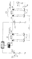
- Fig. 1 there is illustrated a plan view of an arrangement 1 of the preferred embodiment.
- the preferred embodiment is situated on a road e.g. 2 along which traffic flows.
- the arrangement includes a number of devices including a first and second smoky vehicle detection devices (SVDD) 3, 4.
- vehicle positioning devices 6, 7 measure the position of a vehicle.
- Two OCR flash units 9,10 are also provided for use in conjunction with a camera device. The flash units being optional.
- camera units 12, 13 are provided having optical character recognition capabilities.
- a series of digital video devices 16-18 are also provided for capturing video information.
- the system operates in two parts with one part 21 being located at the start of test path and one part 22 being located at the finish of the test path.
- a smoky Heavy Goods Vehicle (HGV) 20 travels past a Smoky Vehicle Detection Device 3 which detects excessive smoke. This enables the output from the Vehicle Positioning Device 6, which, when triggered by the HGV, causes the front of the HGV to be photographed by an OCR capable camera 12. At the finish of the test path a similar process occurs.
- HGV smoky Heavy Goods Vehicle
- the photos taking at the start and finish of the test path are stored in addition to simultaneous video taken via video cameras 16-18.
- Photographs taken at the start and finish of the test path are scanned and OCR is performed on registration plates.
- Photos with matching registration numbers are paired and are then stored in a single encrypted file with video clips of the test path taken between the time of the "start" photograph and the "finish” photograph. This file can then be presented to a human operator at a convenient time and place for adjudication.
- Each installation of the preferred embodiment is individually assessed to determine the most appropriate combination and location of equipment based on the test path properties. Assessment includes, but is not limited to, posted speed, the number of traffic lanes and the ability to position cameras and other equipment in secure locations which are appropriate for their functional operation.
- all cameras are aimed directly into the path of oncoming traffic; all detection devices are operated at right angles to the traffic flow.
- the SVDD devices 3, 4 work on the principle of the obscuration of IR light over an open path which is between the SVDD transmitter and SVDD receiver. This may be accomplished by a transmitter/receiver module with a reflector mounted on the opposite side of the carriageway (not shown), or alternatively a transmitter at one side and receiver at the other side of the carriageway. Such sensing systems are well known in the art. Preferably, the system operates with a response time of less than one second for the detection of HGV smoke as well as a slower averaging system to compensate for changes in ambient atmosphere obscuration and the optical path becoming dirty.
- the SVDD transmitter is typically an IR Light emitting Diode which has its output power controlled by a central programmable logic controller (not shown) which provides the appropriate variable output to compensate for ambient obscuration and dirty optical surfaces and which operates on a long time constant.
- the SVDD receiver is typically an IR PIN Diode which measures the light which is transmitted across the open path. The output from the IR PIN diode operates on a short time constant (typically a few milliseconds). Because the output of the IR PIN Diode should remain constant over the long term, rapid, short term changes provide analogue output signals indicating the presence and the amount of HGV smoke.
- the first piece of equipment in the direction of the traffic flow is the SVDD e.g. 3, 4.
- the beam should not be interrupted by any part of a vehicle, so it is mounted just above the height of the highest vehicle's traffic envelope.
- a corresponding light reflector or beam receiver is mounted on the opposite side of the carriageway at the same height.
- multiple SVDD devices can be provided.
- additional SVDDs can be mounted below the first SVDD, even if this will mean their light path may be blocked by vehicles.
- the PLC is reprogrammed to read the smoke levels recorded by the lowest positioned SVDD which has not had its beam totally blocked by a vehicle.
- the Vehicle Positioning Device (VPD) 6, 7 are a high reliability IR beam barriers, of a type commonly used to detect overheight vehicles or provide light barrier curtains for machinery guards.
- the VPD works on the principle of blocking the IR light over an open path which is between the VPD which may be a combined transmitter / receiver module with a reflector or a separate transmitter with the receiver mounted on the opposite side of the test path.
- the VPD has a response time of a few milliseconds when the beam is broken.
- the VPD has had its output enabled by the SVDD detecting a smoky HGV within a predetermined prior timeframe, the VPD provides a trigger to the PLC indicating the position of the front of the HGV.
- the corresponding High Resolution OCR Still Camera 12, 13 can then be instructed to photograph the front of the HGV, which will include the front registration plate.
- the VPD 6, 7 is the second piece of equipment in the equipment set.
- the VPD is mounted at a height at which all light passenger vehicles would normally pass under it but all heavy vehicles would normally break it. Usually this is not greater than 2.5 metres above the roadway but may be adjusted to local conditions.
- the corresponding light reflector or light receiver is mounted on the opposite side of the carriageway at the same height.
- the VPD 6, 7 is normally positioned not less than 15 metres and not greater than 40 metres downstream of the SVDD 3, 4. The position depends on the posted speed; the lower the posted speed, the shorter the distance.
- the Cameras 12, 13 which record smoky vehicles must be triggered to respond under the appropriate circumstances. That is, when a smoky HGV is at a precise place at the beginning and end of the test path. Both analogue and digital signals from the SVDD's and VPD's can be processed to ensure that cameras are instructed to take and store still photos and video as appropriate.
- a powerful industrial Programmable Logic Controller (PLC) with additional, separate communications interfaces is used in this instance.
- PLC Programmable Logic Controller
- An example of such a PLC is an Allan Bradley Logix 5555 with appropriate I/O Modules and RS Logix Software.
- Driver software within the PLC is configured to control all the processes mentioned above. As well as controlling compensation procedures for light path obscuration of the SVDDs due to dirt build up on the optical path and/or dirty ambient atmosphere, it also controls the selection of the signal from the appropriate SVDD in multiple SVDD installations and the "active window" time of the VPD, based on a speed determining algorithm.
- Still Cameras 12-13 take photos of smoky HGV's at both the start and finish of the test path.
- the number of Still Cameras at the start and/or finish of the test path will depend on each individual installation.
- Still Cameras are typically high quality "digital" cameras which instantaneously download their photograph into computers which are physically resident near to or in the same housing as the camera.
- the computers give the Still Cameras the necessary computing power and storage facility to allow for further processing of the images.
- the Still Cameras are typically located between 5 and 20 metres after the Vehicle Positioning Devices (VPD), depending on the requirements of the particular installation, but irrespective of location, the Still Cameras are aimed to take photographs of HGV's registration plates between 1 and 3 metres after the VPDs.
- VPD Vehicle Positioning Devices
- the Still Cameras would usually be selected to use Infra Red light cameras with compatible IR Flash Guns. This is to avoid the problem during periods of low ambient light levels of steady state high illumination or discharging high power visible light Flash Guns pointing directly at drivers. None the less, visible light cameras can also be used in appropriate circumstances.
- the Still Cameras are directly linked to the PLC Trigger System.
- the command to take a photograph is given by the PLC Trigger System to the Still Cameras over this link.
- the image can be scanned and the registration plate number determined using OCR software.
- the photo and the registration number, together with other relevant information are stored for matching with the same registration plate from the opposite end of the test path.
- appropriate lighting or flash devices e.g. 9, 10 are located to ensure that all registration plates are correctly illuminated for the Still Cameras.
- At least three video cameras 16-18, facing oncoming traffic, are used to video the test path.
- the video cameras are located such that any vehicle can be clearly and continuously viewed by the video cameras over the entire test path.
- the video cameras continually take scene views which are stored digitally.
- "video clips" from each camera with a defined start and finish time (the time of the Still Photographs respectively) may be appended to the Still Camera photographs and other data to complete a Potential Offender File.
- Potential Offender Files can be viewed by a human operator to perform the final adjudication in any decision to proceed with an action against a smoky vehicle.
- Various alternative embodiments can include a link with a vehicle registration database to automatically proceed with an action.
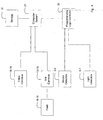
- Fig. 4 there is illustrate schematically one form of the hardware arrangement of the preferred embodiment wherein a programmable logic controller 30 is programmed to operate the smoke detectors (SVDD) 3, 4 and the HGV passage detectors 6, 7. Similarly, the video cameras 16-18 and Still Cameras 12-13 are interconnected to a computer system 31 for download and storage 32 of video information. The computer system 31 can in turn be interconnected with the network for the transfer and review of possible infringement files.
- SVDD smoke detectors
- HGV passage detectors 6 the smoke detectors
- the video cameras 16-18 and Still Cameras 12-13 are interconnected to a computer system 31 for download and storage 32 of video information.
- the computer system 31 can in turn be interconnected with the network for the transfer and review of possible infringement files.
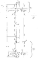
- Fig. 2 and 3 an alternative similar embodiment will now be described. Again the method of the alternative embodiment is shown as applied to a roadway 51, where the vehicle 52 proceeds in a direction from right to left.
- Two detection stations 53 and 54 are provided for detecting the particulate emissions emitted from vehicle 2. As shown in Fig. 2, the second detection station 54 is 240 metres downstream of the first detection station 53.
- Each of the detection stations includes a means e.g. 55 for detecting levels of particulate emissions. More specifically, predetermined levels of particulate emissions are detected by the triggering of a smoke detector beam.
- the detection stations 53 and 54 also include a means 57 for recording information identifying the vehicle if the detected particulate emissions exceed a predetermined level. More specifically, the triggering of the smoke detector 55 opens an output possibility from an interruptible light beam. Upon the vehicle passing through the light beam an image capturing device 57 is activated.
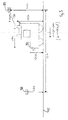
- Fig. 3 where there is shown a schematic side view of a smoky vehicle 52 traversing the roadway 51.
- a smoky vehicle is travelling at a maximum speed of say 108 kph (30m/sec) with a stack 60 at a height of at least 3.2 metres, an exhaust 70 with vertical velocity of 10m/sec and with the smoke detector 55 at a height of 5.2 metres, then a smoky vehicle will travel 6 metres past the detector 55 before the exhaust reaches the level of the smoke detector 55.
- a time of 100 milliseconds is allowed for the detector to respond during which the vehicle travels a further 3 metres, giving a total of 9 metres.
- the stack 60 is placed a maximum 4 metres behind the first part 61 of the vehicle which is 2.6 metres or higher, the light beam 6 should be placed at least 13 metres after the smoke detector as shown in the Fig. 3.
- a first image of the registration number is taken by camera 57.
- a similar process is repeated at the station 54. Should vehicle 52 still be emitting excessive particulates by the time it reaches the second detection station a second image will be produced. With the aid of OCR recognition, a match can be made and the images at both stations are stored and a video taken and stored for later evaluation.
- vehicle 52 may trigger the smoke detector at the first station 53 causing the interruptible light beam mode to switch to operational mode and thus activate the camera upon the vehicle passing through the light beam.
- airflow will normally be in the direction of the traffic except at the tunnel exit portal. This means that exhaust gases from a vehicle will not be blown against the direction of travel allowing the time which an exhaust plume passes a certain point after the exhaust stack to be calculated. This calculation is based on the speed of the smoky vehicle, the height of the point above the stack and the vertical velocity of the exhaust outlet. It will be appreciated that this calculation is significant for determining the distance that the vehicle has travelled by the time the exhaust plume has been detected in order that the camera may be placed at an appropriate distance from the smoke detector. Ideally the positioning is fine tuned during operations.
- These smoke detectors are made of an infrared beam transmitter and a receiver.
- the infrared beam emitted by the transmitter is directed to the receiver that converts the incident radiation in an electric signal.
- smoke travels up and intercepts the infrared beam causing a corresponding change in the electrical state of the receiver which is measured with respect to time.
- High rate changes are the result of the instantaneous introduction of a new high level of smoke, which indicates the passage of a smoky vehicle.
- the method of the alternative embodiment is based on an interaction between the smoke detector used to detect a smoky vehicle and a camera system used to capture an image of the offending vehicle.
- This is preferably achieved with the use of a light beam connected to the PLC Control System
- a vehicle passes through and breaks the light beam which, instantly operates a camera.
- the light beam is placed at a suitable height so that only vehicles of interest, in this case heavy vehicles/trucks, have a height sufficient to pass through the beam.
- Vehicles like cars, bikes, vans and four wheel drives are not being targeted by the embodiment and will not activate the camera since they will not break the light beam.
- the camera need only be triggered if the vehicle is a smoky vehicle. Accordingly, the output of the interrupted light beam only triggers the camera if the smoke detector has also been triggered immediately prior.
- a suitable camera system for carrying out the method of the alternative embodiment is for example the Redflex system available from Redflex Traffic Systems of Scottsdale, Arizona and Melbourne, Victoria, Australia.
Landscapes
- Physics & Mathematics (AREA)
- General Physics & Mathematics (AREA)
- Traffic Control Systems (AREA)
Applications Claiming Priority (2)
| Application Number | Priority Date | Filing Date | Title |
|---|---|---|---|
| AU2002952605 | 2002-11-12 | ||
| AU2002952605A AU2002952605A0 (en) | 2002-11-12 | 2002-11-12 | Detection and identification of vehicles with excess particulates in exhaust gas |
Publications (2)
| Publication Number | Publication Date |
|---|---|
| EP1420239A2 true EP1420239A2 (de) | 2004-05-19 |
| EP1420239A3 EP1420239A3 (de) | 2005-02-16 |
Family
ID=28795992
Family Applications (1)
| Application Number | Title | Priority Date | Filing Date |
|---|---|---|---|
| EP03025764A Withdrawn EP1420239A3 (de) | 2002-11-12 | 2003-11-11 | Erfassung und Identifikation von Fahrzeugen mit übermässigem Partikelgehalt im Abgas |
Country Status (4)
| Country | Link |
|---|---|
| US (1) | US7036353B2 (de) |
| EP (1) | EP1420239A3 (de) |
| AU (1) | AU2002952605A0 (de) |
| CA (1) | CA2448365A1 (de) |
Cited By (5)
| Publication number | Priority date | Publication date | Assignee | Title |
|---|---|---|---|---|
| CN103021184A (zh) * | 2012-12-26 | 2013-04-03 | 江苏大学 | 遮挡车牌车辆的辅助辨别方法及系统 |
| CN103646548A (zh) * | 2013-12-06 | 2014-03-19 | 镇江市星禾物联科技有限公司 | 一种基于图像识别技术对车牌的识别方法 |
| CN105096620A (zh) * | 2015-07-10 | 2015-11-25 | 南京理工大学 | 一种高速公路机动车气态污染物排放的测定、评估与警示装置及方法 |
| CN106680212A (zh) * | 2016-12-31 | 2017-05-17 | 中国科学技术大学 | 一种基于路面反射的垂直式机动车尾气遥测系统 |
| CN108389417A (zh) * | 2018-04-24 | 2018-08-10 | 西南交通大学 | 一种考虑空气污染暴露的混合用户出行诱导方法 |
Families Citing this family (13)
| Publication number | Priority date | Publication date | Assignee | Title |
|---|---|---|---|---|
| GB0500687D0 (en) * | 2005-01-14 | 2005-02-23 | Unidata Europ Ltd | Particulate detector |
| JP4773933B2 (ja) * | 2006-12-01 | 2011-09-14 | 三菱重工業株式会社 | 車軸重量違反車両検出システム |
| KR100963279B1 (ko) * | 2007-02-08 | 2010-06-11 | 안순현 | 매연차량 자동판독 시스템 및 그 방법 |
| JP5697587B2 (ja) * | 2011-12-09 | 2015-04-08 | 三菱電機株式会社 | 車両火災検出装置 |
| KR101144829B1 (ko) * | 2012-02-21 | 2012-05-11 | 양장은 | 매연차량 검출장치 |
| US9313379B2 (en) * | 2012-09-24 | 2016-04-12 | Illinois State Toll Highway Authority | Camera washing system |
| DE102014001704B4 (de) * | 2014-02-08 | 2023-08-10 | Dräger Safety AG & Co. KGaA | Gasdetektionsvorrichtung |
| US10354459B2 (en) | 2016-10-06 | 2019-07-16 | Ford Global Technologies, Llc | Hydrocarbon-emissions monitoring |
| DE102018203858B4 (de) * | 2018-03-14 | 2025-09-11 | Ford Global Technologies, Llc | Verfahren zum Anpassen von Feinstaubmesswerten |
| US10847029B2 (en) * | 2018-10-09 | 2020-11-24 | Here Global B.V. | Method, apparatus, and system for automatic road closure detection |
| CN112580401A (zh) * | 2019-09-29 | 2021-03-30 | 杭州海康威视数字技术股份有限公司 | 车辆检测方法及装置 |
| CN113390766B (zh) * | 2020-03-12 | 2023-07-25 | 杭州海康威视数字技术股份有限公司 | 尾气排放检测方法、装置及设备、存储介质 |
| CN112289022B (zh) * | 2020-09-29 | 2022-02-25 | 西安电子科技大学 | 基于时空背景比对的黑烟车检测判定方法及系统 |
Family Cites Families (7)
| Publication number | Priority date | Publication date | Assignee | Title |
|---|---|---|---|---|
| US5583765A (en) * | 1994-08-23 | 1996-12-10 | Grumman Aerospace Corporation | Remote system for monitoring the weight and emission compliance of trucks and other vehicles |
| US5589629A (en) * | 1995-04-25 | 1996-12-31 | Quinn; Stephen J. | Method and apparatus for testing vehicle exhaust emissions |
| US5719396A (en) * | 1996-07-01 | 1998-02-17 | Envirotest Systems Corp. | Systems and methods for determining compliance of moving vehicles with emission-concentration standards |
| ES2258858T3 (es) * | 1998-10-30 | 2006-09-01 | Envirotest Systems, Inc. | Detector remoto para carriles multiples. |
| AU2395700A (en) * | 1998-12-31 | 2000-07-31 | Envirotest Systems Corp. | Data processing and validation |
| HK1049205B (en) * | 1999-12-29 | 2014-05-16 | Envirotest Systems Holdings Corp | System and method for remote analysis of small engine vehicle emissions |
| US6455851B1 (en) * | 2000-03-28 | 2002-09-24 | Air Instruments And Measurement, Inc. | Spectroscopic remote sensing exhaust emission monitoring system |
-
2002
- 2002-11-12 AU AU2002952605A patent/AU2002952605A0/en not_active Abandoned
-
2003
- 2003-11-05 CA CA002448365A patent/CA2448365A1/en not_active Abandoned
- 2003-11-11 EP EP03025764A patent/EP1420239A3/de not_active Withdrawn
- 2003-11-12 US US10/706,732 patent/US7036353B2/en not_active Expired - Fee Related
Non-Patent Citations (1)
| Title |
|---|
| CHEN G ET AL: "Feasibility of Remote Sensing of Particulate Emissions from Heavy-Duty Vehicles", SAE CONFERENCE INTERNATIONAL CONGRESS AND EXPOSITION, vol. 1161, 26 February 1996 (1996-02-26), pages 111 - 124, XP009009832 * |
Cited By (8)
| Publication number | Priority date | Publication date | Assignee | Title |
|---|---|---|---|---|
| CN103021184A (zh) * | 2012-12-26 | 2013-04-03 | 江苏大学 | 遮挡车牌车辆的辅助辨别方法及系统 |
| CN103021184B (zh) * | 2012-12-26 | 2015-08-26 | 江苏大学 | 遮挡车牌车辆的辅助辨别方法及系统 |
| CN103646548A (zh) * | 2013-12-06 | 2014-03-19 | 镇江市星禾物联科技有限公司 | 一种基于图像识别技术对车牌的识别方法 |
| CN105096620A (zh) * | 2015-07-10 | 2015-11-25 | 南京理工大学 | 一种高速公路机动车气态污染物排放的测定、评估与警示装置及方法 |
| CN105096620B (zh) * | 2015-07-10 | 2017-12-12 | 南京理工大学 | 一种高速公路机动车气态污染物排放的测定、评估与警示装置及方法 |
| CN106680212A (zh) * | 2016-12-31 | 2017-05-17 | 中国科学技术大学 | 一种基于路面反射的垂直式机动车尾气遥测系统 |
| CN106680212B (zh) * | 2016-12-31 | 2019-04-26 | 中国科学技术大学 | 一种基于路面反射的垂直式机动车尾气遥测系统 |
| CN108389417A (zh) * | 2018-04-24 | 2018-08-10 | 西南交通大学 | 一种考虑空气污染暴露的混合用户出行诱导方法 |
Also Published As
| Publication number | Publication date |
|---|---|
| US20040144186A1 (en) | 2004-07-29 |
| EP1420239A3 (de) | 2005-02-16 |
| US7036353B2 (en) | 2006-05-02 |
| CA2448365A1 (en) | 2004-05-12 |
| AU2002952605A0 (en) | 2002-11-28 |
Similar Documents
| Publication | Publication Date | Title |
|---|---|---|
| US7036353B2 (en) | Detection and identification of vehicles with excess particulates in exhaust gases | |
| KR101832918B1 (ko) | 자율주행 자동차 영상인식 주행시험 시뮬레이션 시스템 | |
| CN112997196B (zh) | 用于确定物理对象的缺陷的系统及方法 | |
| CN110085029B (zh) | 基于轨道式巡检机器人的高速公路巡检系统与方法 | |
| JP3275620B2 (ja) | 自動課金システム | |
| US8294595B1 (en) | Speed detector for moving vehicles | |
| KR100963279B1 (ko) | 매연차량 자동판독 시스템 및 그 방법 | |
| WO2020189475A1 (ja) | 移動体監視システム、移動体監視システムの制御サーバ、及び移動体監視方法 | |
| KR102459906B1 (ko) | 듀얼밴드 적외선 카메라를 이용한 승차인원 검지 시스템 및 그 방법 | |
| CN113574576A (zh) | 用于通过低于后车与前车之间的允许间距来识别交通违法行为的方法和装置 | |
| KR100695348B1 (ko) | 비매설형 레이저 센서 차량번호 자동인식장치 및 레이저 센서와 cctv를 이용한 터널 방재 관리시스템 및 방법 | |
| CN114495014A (zh) | 智慧社区管理系统和智慧社区管理系统控制方法 | |
| KR20090122168A (ko) | 매연차량 자동판독 시스템 및 그 방법 | |
| EP1276086B1 (de) | System zur Überwachung und Steuerung der Durchschnittsgeschwindigkeit von sich bewegenden Fahrzeugen und zur Untersuchung des Verkehrs auf Strassen und Autobahnen | |
| AU2003261528B2 (en) | Detection and identification of vehicles with excess particulates in exhaust gases | |
| KR100374945B1 (ko) | 복합 교통단속 장치와 제어 방법 | |
| KR20140011148A (ko) | 협의의 구간단속 시스템 | |
| WO1996013023A1 (en) | A device for the identification of vehicles at a control station | |
| JP2968473B2 (ja) | 速度監視記録装置 | |
| WO2014171897A1 (en) | Apparatus, system and method for remote detection of vehicle exhaust | |
| KR20100064011A (ko) | 불법 유턴 차량 단속 장치 및 그 방법 | |
| CN113734207A (zh) | 车辆安全防护系统、方法及车辆 | |
| KR102459091B1 (ko) | 과속 단속 장치 | |
| KR102390947B1 (ko) | 차량 검지 시스템 | |
| KR102900594B1 (ko) | Its 기반 교통량 데이터 분석을 통한 도로 혼잡도 예측 및 경고 방법, 장치 및 시스템 |
Legal Events
| Date | Code | Title | Description |
|---|---|---|---|
| PUAI | Public reference made under article 153(3) epc to a published international application that has entered the european phase |
Free format text: ORIGINAL CODE: 0009012 |
|
| AK | Designated contracting states |
Kind code of ref document: A2 Designated state(s): AT BE BG CH CY CZ DE DK EE ES FI FR GB GR HU IE IT LI LU MC NL PT RO SE SI SK TR |
|
| AX | Request for extension of the european patent |
Extension state: AL LT LV MK |
|
| PUAL | Search report despatched |
Free format text: ORIGINAL CODE: 0009013 |
|
| AK | Designated contracting states |
Kind code of ref document: A3 Designated state(s): AT BE BG CH CY CZ DE DK EE ES FI FR GB GR HU IE IT LI LU MC NL PT RO SE SI SK TR |
|
| AX | Request for extension of the european patent |
Extension state: AL LT LV MK |
|
| 17P | Request for examination filed |
Effective date: 20050421 |
|
| AKX | Designation fees paid |
Designated state(s): AT BE BG CH CY CZ DE DK EE ES FI FR GB GR HU IE IT LI LU MC NL PT RO SE SI SK TR |
|
| RAP1 | Party data changed (applicant data changed or rights of an application transferred) |
Owner name: UNITED GROUP RAIL PTY LTD |
|
| 17Q | First examination report despatched |
Effective date: 20090310 |
|
| STAA | Information on the status of an ep patent application or granted ep patent |
Free format text: STATUS: THE APPLICATION IS DEEMED TO BE WITHDRAWN |
|
| 18D | Application deemed to be withdrawn |
Effective date: 20090720 |