EP1420427A1 - Actionneur électromagnétique. - Google Patents
Actionneur électromagnétique. Download PDFInfo
- Publication number
- EP1420427A1 EP1420427A1 EP03104052A EP03104052A EP1420427A1 EP 1420427 A1 EP1420427 A1 EP 1420427A1 EP 03104052 A EP03104052 A EP 03104052A EP 03104052 A EP03104052 A EP 03104052A EP 1420427 A1 EP1420427 A1 EP 1420427A1
- Authority
- EP
- European Patent Office
- Prior art keywords
- magnetic circuit
- electromagnetic actuator
- fixed part
- coil
- central opening
- Prior art date
- Legal status (The legal status is an assumption and is not a legal conclusion. Google has not performed a legal analysis and makes no representation as to the accuracy of the status listed.)
- Granted
Links
- 230000005291 magnetic effect Effects 0.000 claims abstract description 89
- 230000005284 excitation Effects 0.000 claims abstract description 36
- 230000003213 activating effect Effects 0.000 abstract 1
- XEEYBQQBJWHFJM-UHFFFAOYSA-N Iron Chemical compound [Fe] XEEYBQQBJWHFJM-UHFFFAOYSA-N 0.000 description 10
- RYGMFSIKBFXOCR-UHFFFAOYSA-N Copper Chemical compound [Cu] RYGMFSIKBFXOCR-UHFFFAOYSA-N 0.000 description 6
- 229910052802 copper Inorganic materials 0.000 description 6
- 239000010949 copper Substances 0.000 description 6
- 229910052742 iron Inorganic materials 0.000 description 5
- 238000004519 manufacturing process Methods 0.000 description 5
- 239000000463 material Substances 0.000 description 4
- 239000003302 ferromagnetic material Substances 0.000 description 3
- 239000000696 magnetic material Substances 0.000 description 3
- 238000004804 winding Methods 0.000 description 3
- 230000000295 complement effect Effects 0.000 description 1
- 239000004020 conductor Substances 0.000 description 1
- 230000000694 effects Effects 0.000 description 1
- 230000005294 ferromagnetic effect Effects 0.000 description 1
- 230000035699 permeability Effects 0.000 description 1
- 230000000717 retained effect Effects 0.000 description 1
Images

Classifications
-
- H—ELECTRICITY
- H01—ELECTRIC ELEMENTS
- H01H—ELECTRIC SWITCHES; RELAYS; SELECTORS; EMERGENCY PROTECTIVE DEVICES
- H01H50/00—Details of electromagnetic relays
- H01H50/16—Magnetic circuit arrangements
- H01H50/36—Stationary parts of magnetic circuit, e.g. yoke
Definitions
- the present invention relates to an electromagnetic actuator for an apparatus electric switch, in particular for a relay, a contactor or a contactor circuit breaker, the magnetic circuit of which is wound around the excitation coil of the actuator.
- the invention also relates to a switch device provided with such a actuator.
- Electromagnetic actuators or electromagnets, of devices switches used to switch the power supply to an electric load connected downstream of the device. They usually have a magnetic circuit made of material ferromagnetic, such as iron, which consists of a fixed part and a mobile part.
- the movable part linked to movable contacts, moves between an open position and a closed position under the action of an electric current flowing in a coil control, called excitation coil, constituted for example by a winding of a wire conductor, usually copper.
- excitation coil constituted for example by a winding of a wire conductor, usually copper.
- the magnetic circuit crosses once the space inside the excitation coil.
- the power supplied by an electromagnetic actuator must obviously be adapted to the power current flowing in the electrical load to be controlled so to be able to open and close the supply circuit quickly and safely, for an optimized cost.
- the force of attraction of the mobile part towards the fixed part of the magnetic circuit is practically a function of the square of the intensity of the electric control current but also the square of the number of turns of the coil surrounding the magnetic circuit. Now, this force must be large enough to be able to switch quickly and load efficiently, especially in large gauge switchgear. This need may then require an increase in the number of turns and / or the current control and therefore the size of the excitation coil. But the copper used in the coil is a very expensive material. We therefore constantly seek to minimize the amount of copper used necessary to obtain a given attractive force.
- the ferromagnetic material used to make the magnetic circuit such as that for example iron, is much less expensive than the copper used to form the coil turns. It would therefore be particularly advantageous and economical to minimize the quantity of copper required by compensating for it by an increase in the quantity of iron used.
- One of the aims of the present invention is to meet this objective of reducing cost while offering a simple structure to manufacture and easy to assemble in a device light switch.
- the invention describes an electromagnetic actuator for apparatus electric switch, comprising a control circuit composed of a coil excitation with a central opening and a magnetic circuit composed of a part fixed and a movable pallet capable of moving when an electric current flows in the excitation coil, thus closing the magnetic circuit.
- the fixed part of the magnetic circuit passes through the central opening of the excitation coil several times in forming at least one loop.
- the fixed part of the circuit magnetic crosses twice the central opening of the excitation coil forming a loop.
- the magnetic field created during the passage of an electric current in the coil is multiplied by a factor of two compared to a actuator with a conventional magnetic circuit crossing only once this coil. Therefore, we advantageously obtain a force of attraction which is multiplied by a factor of four for the same number of turns of the coil and the same intensity of electric control current, modifying only the circuit structure magnetic. Thanks to this advantage, another object of the invention is to be able to increase the attractive force for a given volume and size of the actuator or power reduce this size while keeping the same attractive force.
- the fixed part of the magnetic circuit comprises a base juxtaposed with two non-contiguous arms crossing the central opening of the coil excitation.
- the invention describes an actuator which comprises a control circuit composed of X excitation coils connected in series and provided each with a central opening, and a magnetic circuit composed of a movable pallet and of X fixed parts magnetically connected to each other, each fixed part of the circuit magnetic crossing several times the central opening of an excitation coil corresponding by forming at least one loop.
- An electromagnetic actuator is used in an electrical switch device relay, contactor or contactor / circuit breaker type.
- the purpose of the actuator is to switch the supply of an electric charge to be controlled by acting on the opening or closing of movable contacts linked with a movable part of the actuator, depending on a electric control current.
- an actuator electromagnetic includes a control circuit composed of an excitation coil 20 and a deformable magnetic circuit 10 comprising a fixed part 11 and a mobile part 19.
- the magnetic circuit 10 is made of a material of high magnetic permeability such as ferromagnetic material.
- the excitation coil 20 comprises a frame 21, made of a material non-magnetic, on which is wound a winding of N turns of a conductive wire crossed by the electric control current I.
- the frame 21 has a central opening whose dimensions are adapted to be able to be crossed several times by the circuit magnetic 10. In the embodiments presented, the fixed part 11 of the circuit magnetic 10 crosses twice the central opening of the excitation coil 20 forming a loop.
- the mobile part 19 of the magnetic circuit 10 is constituted by a mobile pallet 19.
- the fixed part 11 of the magnetic circuit 10 comprises a base 12, in the form approximate U spanning the coil 20.
- the base 12 has two uprights vertical 121,122 on each side of a central base 123 and partially surrounds the coil excitation 20 without passing through the central opening of the armature 21.
- the armature 21 of the coil 20 is placed on the central base 123, so that the two vertical uprights 121, 122 are positioned on either side of the coil 20.
- the fixed part 11 also comprises two transverse arms 13, 14 distinct and not contiguous which are each juxtaposed against one of the vertical uprights, respectively 121,122, each passing through the central opening of the frame 21.
- the transverse arms 13 and 14 are of identical shape and pass through the central opening along two axes substantially parallel.
- Simple suitable guiding means for example made of plastic, can be advantageously fitted inside the central opening of the frame 21, so as to guide and maintain the two transverse arms 13, 14 at a distance sufficient from each other, so as not to disturb the circulation of the magnetic field and for avoid leakage between the arms 13,14.
- Figures 1 and 2 thus show that the transverse arm 13 has a first end 136 which comes to be juxtaposed against the internal wall of the vertical upright 121 (in the occurrence against the top of the inner wall), and has a second upper face 135 facing one end of the movable pallet 19.
- the transverse arm 14 has a first end which is juxtaposed against the wall internal of the other vertical upright 122 (in this case against the top of the internal wall), and has a second upper face 145 coming opposite the opposite end of the movable pallet 19.
- the air gap of the magnetic circuit 10 is then formed by the space formed between the ends of the movable pallet 19 and the second upper faces 135,145 of transverse arms 13,14.
- the various elements in contact 135,145,19, 136,121,122 are arranged to minimize any residual air gaps between them, when they are joined.
- the faces 135, 145 are flat to juxtapose against a flat underside of the movable pallet 19. From even, the first ends are flat to be juxtaposed against the internal walls vertical uprights. We could also consider other forms complementary between elements in contact.
- the loop of the fixed part 11 surrounding part of the coil 20 and passing through the central opening of the coil 20 is therefore formed by: a transverse arm 13, the base 12 and the other arm 14.
- the base 12 is arranged so that its two vertical uprights 121, 122 are positioned on the side and on the other side of the coil 20, the magnetic field B circulating in the arms 13,14 passes through always the central opening of the coil 20 in the same direction. Consequently, the magnetic field B advantageously crosses the opening twice in the same direction excitation coil center 20.
- the field magnetic B created is proportional to (N * I), N representing the number of turns of the coil and I the intensity of the control current.
- N representing the number of turns of the coil
- I the intensity of the control current.
- the magnetic field B is then proportional to (Y * N * I). So, in the example of Figures 1 and 2, the magnetic field B is proportional to (2 * N * I) until saturation of magnetic materials, i.e. it is twice as much important that in a conventional solution where the magnetic circuit would cross only one times the central opening of the excitation coil.
- the attraction force F would have been increased by a factor equal to the square of the number of passes Y in the opening of the coil.
- the electromagnetic actuator comprises a control circuit composed of X excitation coils connected in series and provided each with a central opening, and a magnetic circuit composed of a single part mobile, such as a mobile pallet, and X fixed parts magnetically linked together, each fixed part of the magnetic circuit passing several times through the central opening of a corresponding excitation coil by forming at least one loop.
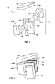
- Figures 3 and 4 show a control circuit composed of two 20,20 'coils electrically connected in series. These excitation coils are for example each identical to the coil 20 of FIG. 2.
- the magnetic circuit 10 ' has a 19 'movable pallet and two fixed parts magnetically connected to each other by a piece of link 18 ', such as a rod made of ferromagnetic material.
- Each fixed part is by example identical to the fixed part 11 described in FIGS. 1 and 2.
- the first part fixed and the second fixed part each have a base, respectively 12 and 12 ', juxtaposed with two transverse arms, respectively 13,14 and 13 ', 14', which cross the central opening of the corresponding excitation coil, respectively 20 and 20 '.
- the role of the connecting piece 18 ' is to connect the two middle arms of the circuit magnetic 10 ', namely an arm 14 of the first fixed part and an arm 13' of the second adjacent fixed part, so as to ensure the continuity of the circulating magnetic field throughout the magnetic circuit 10 '.
- the connecting piece 18 ' is designed to connect the fixed parts by spanning the 20.20 'coils.
- the two ends of the movable pallet 19 ' are provided with two protuberances 191 ', 192' each having a pole face, or iron return face, which are placed facing the upper faces of the arms placed at the two ends of the fixed parts of the magnetic circuit 10 '.
- the pole face 191 ′ is opposite of the upper face 135 of the arm 13 of the first fixed part and the pole face 192 'is in opposite the upper face 145 'of the arm 14' of the second fixed part.
- the air gap of the circuit magnetic field 10 ' is then formed by the space formed between the polar faces 191', 192 'of the movable pallet and the upper faces 135, 145 'of the corresponding arms.
- the projections 191 ', 192' have a sufficient height to allow the positioning of the movable pallet 19 'above the connecting piece 18' at a sufficient distance so as not to impede the circulation of the magnetic field in the magnetic circuit 10 'nor generate too much leaks between the connecting piece 18 'and the movable pallet 19', even in the attracted position.
- the magnetic field B ' created by the circulation of a control current I in the 2 * N turns of the coils 20,20' in series, is proportional to (2 * (2 * N) * I ) until saturation of the magnetic materials, so that the attraction force F 'is then proportional to 16 * (N * I) 2 .
- the difference compared to a conventional actuator is particularly advantageous since a conventional actuator, that is to say one whose magnetic circuit would only pass through each coil 20,20 'once, and comprising 2 * N turns, does not would provide an attraction force proportional to 4 * (N * I) 2 .
- an extension of this embodiment makes it possible to use X coils in series, X fixed parts of magnetic circuit in series by means of X-1 connecting pieces and 1 movable pallet, thus providing a proportional force of attraction. to (X * (2 * N) * I) 2 .
- the arrangements described in the patent also have the advantage of offer an actuator that is very easy to assemble during its manufacture. Indeed, due to the presence of the two separate transverse arms composing the fixed part, the loop of the magnetic circuit around the coil can be assembled as follows: the armature 21 with the coil 20 already wound up is first placed on the base 123 of the base 12 between the vertical uprights 121, 122, then the arms 13 and 14 are inserted, possibly guided in the opening by simple guide means, on each side in the opening central of the coil 20 to be pressed against the uprights 121,122. All the actuator can then be inserted as is in a housing of the switch device maintaining the arms 13 and 14 in position, without requiring other means of attachment of arms.
Landscapes
- Physics & Mathematics (AREA)
- Electromagnetism (AREA)
- Electromagnets (AREA)
- Reciprocating, Oscillating Or Vibrating Motors (AREA)
- Valve Device For Special Equipments (AREA)
- Fluid-Damping Devices (AREA)
- Air Bags (AREA)
- Driving Mechanisms And Operating Circuits Of Arc-Extinguishing High-Tension Switches (AREA)
Abstract
Description
- la figure 1 schématise un exemple d'un actionneur électromagnétique selon l'invention,
- la figure 2 montre une vue éclatée du circuit magnétique de l'actionneur de la figure 1 avec une circulation fictive d'un champ magnétique,
- les figures 3 et 4 représentent un autre exemple d'un actionneur électromagnétique, la figure 3 montrant le circuit magnétique seul et la figure 4 montrant le circuit magnétique assemblé avec les bobines d'excitation.
- la palette mobile 19,
- la face supérieure 135 d'un des deux bras transversaux, par exemple le bras 13, puis l'extrémité 136 du bras 13,
- le premier montant vertical 121 de l'embase 12,
- le socle 123 de l'embase 12,
- le second montant vertical 122 de l'embase 12,
- l'extrémité de l'autre bras transversal 14, puis la face supérieure 145 du bras 14,
- la palette mobile 19.
Claims (10)
- Actionneur électromagnétique pour appareil électrique interrupteur, comprenant un circuit de commande composé d'une bobine d'excitation (20) dotée d'une ouverture centrale et un circuit magnétique (10) composé d'une partie fixe (11) et d'une palette mobile (19) susceptible de se déplacer quand un courant électrique circule dans la bobine d'excitation (20), caractérisé en ce que la partie fixe (11) du circuit magnétique (10) traverse plusieurs fois l'ouverture centrale de la bobine d'excitation (20) en formant au moins une boucle.
- Actionneur électromagnétique selon la revendication 1, caractérisé en ce que la partie fixe (11) du circuit magnétique (10) traverse deux fois l'ouverture centrale de la bobine d'excitation (20) en formant une boucle.
- Actionneur électromagnétique selon la revendication 2, caractérisé en ce que la partie fixe (11) du circuit magnétique (10) comprend une embase (12) juxtaposée à deux bras (13,14) non jointifs traversant l'ouverture centrale de la bobine d'excitation (20).
- Actionneur électromagnétique selon la revendication 3, caractérisé en ce que les deux bras (13,14) sont de forme identique.
- Actionneur électromagnétique selon la revendication 3, caractérisé en ce que le champ magnétique circulant dans le circuit magnétique (10) parcourt un chemin passant par la palette mobile (19), un premier des deux bras (13), l'embase (12), le second bras (14) avant de revenir à la palette mobile (19), le passage du champ magnétique se faisant dans le même sens dans les deux bras (13,14).
- Actionneur électromagnétique selon l'une des revendications précédentes, caractérisé en ce qu'il comprend un circuit de commande composé de X bobines d'excitation (20,20') montées en série et dotées chacune d'une ouverture centrale, et un circuit magnétique (10') composé d'une palette mobile (19') et de X parties fixes reliées magnétiquement entre elles, chaque partie fixe du circuit magnétique traversant plusieurs fois l'ouverture centrale d'une bobine d'excitation (20,20') correspondante en formant au moins une boucle.
- Actionneur électromagnétique selon la revendication 6, caractérisé en ce que le circuit de commande est composé de deux bobines d'excitation (20,20') montées en série, et le circuit magnétique (10') est composé d'une palette mobile (19') et de deux parties fixes reliées magnétiquement entre elles.
- Actionneur électromagnétique selon la revendication 6, caractérisé en ce que chaque partie fixe du circuit magnétique (10') comporte une embase (12,12') juxtaposée à un premier bras (13,13') et à un second bras (14,14') traversant chacun l'ouverture centrale de la bobine d'excitation correspondante (20,20').
- Actionneur électromagnétique selon la revendication 8, caractérisé en ce que le circuit magnétique (10') comporte une pièce de liaison (18') entre un bras (14) d'une première partie fixe du circuit magnétique et un bras (13') d'une seconde partie fixe adjacente du circuit magnétique.
- Appareil électrique interrupteur caractérisé en ce qu'il comporte un actionneur électromagnétique selon l'une des revendications précédentes.
Applications Claiming Priority (2)
| Application Number | Priority Date | Filing Date | Title |
|---|---|---|---|
| FR0214350A FR2847071B1 (fr) | 2002-11-13 | 2002-11-13 | Actionneur electromagnetique |
| FR0214350 | 2002-11-13 |
Publications (2)
| Publication Number | Publication Date |
|---|---|
| EP1420427A1 true EP1420427A1 (fr) | 2004-05-19 |
| EP1420427B1 EP1420427B1 (fr) | 2011-06-15 |
Family
ID=32116631
Family Applications (1)
| Application Number | Title | Priority Date | Filing Date |
|---|---|---|---|
| EP03104052A Expired - Lifetime EP1420427B1 (fr) | 2002-11-13 | 2003-11-03 | Actionneur électromagnétique. |
Country Status (4)
| Country | Link |
|---|---|
| EP (1) | EP1420427B1 (fr) |
| AT (1) | ATE513304T1 (fr) |
| ES (1) | ES2366433T3 (fr) |
| FR (1) | FR2847071B1 (fr) |
Cited By (1)
| Publication number | Priority date | Publication date | Assignee | Title |
|---|---|---|---|---|
| EP1952516A1 (fr) * | 2005-11-22 | 2008-08-06 | Schneider Electric Industries S.A.S. | Dispositif autonome de generation d'energie electrique |
Families Citing this family (1)
| Publication number | Priority date | Publication date | Assignee | Title |
|---|---|---|---|---|
| FR2864329B1 (fr) * | 2003-12-19 | 2006-01-27 | Schneider Electric Ind Sas | Actionneur electromecanique |
Citations (2)
| Publication number | Priority date | Publication date | Assignee | Title |
|---|---|---|---|---|
| US2381080A (en) * | 1942-12-05 | 1945-08-07 | William A Ray | Electromagnetic relay |
| EP0709865A1 (fr) * | 1994-10-26 | 1996-05-01 | Lem S.A. | Procédé et dispositif de couplage de matériau magnétique avec enroulements électriques |
-
2002
- 2002-11-13 FR FR0214350A patent/FR2847071B1/fr not_active Expired - Fee Related
-
2003
- 2003-11-03 ES ES03104052T patent/ES2366433T3/es not_active Expired - Lifetime
- 2003-11-03 EP EP03104052A patent/EP1420427B1/fr not_active Expired - Lifetime
- 2003-11-03 AT AT03104052T patent/ATE513304T1/de not_active IP Right Cessation
Patent Citations (2)
| Publication number | Priority date | Publication date | Assignee | Title |
|---|---|---|---|---|
| US2381080A (en) * | 1942-12-05 | 1945-08-07 | William A Ray | Electromagnetic relay |
| EP0709865A1 (fr) * | 1994-10-26 | 1996-05-01 | Lem S.A. | Procédé et dispositif de couplage de matériau magnétique avec enroulements électriques |
Cited By (1)
| Publication number | Priority date | Publication date | Assignee | Title |
|---|---|---|---|---|
| EP1952516A1 (fr) * | 2005-11-22 | 2008-08-06 | Schneider Electric Industries S.A.S. | Dispositif autonome de generation d'energie electrique |
Also Published As
| Publication number | Publication date |
|---|---|
| EP1420427B1 (fr) | 2011-06-15 |
| FR2847071B1 (fr) | 2004-12-24 |
| ES2366433T3 (es) | 2011-10-20 |
| FR2847071A1 (fr) | 2004-05-14 |
| ATE513304T1 (de) | 2011-07-15 |
Similar Documents
| Publication | Publication Date | Title |
|---|---|---|
| EP0177380B1 (fr) | Dispositif de commutation à composition variable réalisable par assemblage d'éléments modulaires | |
| EP0869519B1 (fr) | Moteur planaire magnétique et micro-actionneur magnétique comportant un tel moteur | |
| FR2815465A1 (fr) | Dispositif de commutation | |
| FR2569298A1 (fr) | Electro-aimant polarise a fonctionnement bi- ou mono-stable | |
| EP1818959B1 (fr) | Dispositif de commutation électrique aux contacts électriques renforcés | |
| EP1420427B1 (fr) | Actionneur électromagnétique. | |
| FR2623325A1 (fr) | Ensemble de commutateur electrique etanche pour appareils electriques | |
| FR2736201A1 (fr) | Relais electromagnetique | |
| FR2581477A1 (fr) | Appareil interrupteur protege contre les courants de court-circuit | |
| EP0693764B1 (fr) | Disjoncteur électrique à actionneur électromagnétique pour calibres élevés | |
| EP1792326B1 (fr) | Actionneur electromagnetique bistable a serrure integree | |
| FR2652198A1 (fr) | Dispositif interrupteur limiteur de courant. | |
| EP0032331A1 (fr) | Interrupteur à contacts mouillés et à commande magnétique, et relais électrique comportant un tel interrupteur | |
| EP1327253A1 (fr) | Dispositif de coupure d'un appareil interrupteur | |
| FR2829869A1 (fr) | Appareil electrique interrupteur muni d'un dispositif de commutation de contact | |
| EP1697955B1 (fr) | Actionneur electromecanique | |
| EP0061383B1 (fr) | Interrupteur à position de fonctionnement indifférente et relais utilisant un tel interrupteur | |
| EP4107768B1 (fr) | Chambre de coupure à soufflage magnétique pour un appareil de coupure électrique et appareil de coupure électrique équipé d'une telle chambre | |
| FR2977067A1 (fr) | Dispositif de guidage de l'arc dans un appareil de protection electrique et appareil de protection electrique comportant un tel dispositif | |
| FR2807871A1 (fr) | Electroaimant pour appareil interrupteur comprenant deux enroulements montes en serie ou en parallele | |
| EP1473749B1 (fr) | Dispositif de commande à hystérésis | |
| FR2809860A1 (fr) | Electroaimant avec bobine amovible | |
| FR2919754A1 (fr) | Relais bistable | |
| FR3151425A1 (fr) | Déclencheur électromagnétique du type relais polarisé à haute sensibilité et appareillage électrique différentiel associé | |
| FR2789512A1 (fr) | Relais electromagnetique a capot enfermant la partie constitutive du relais |
Legal Events
| Date | Code | Title | Description |
|---|---|---|---|
| PUAI | Public reference made under article 153(3) epc to a published international application that has entered the european phase |
Free format text: ORIGINAL CODE: 0009012 |
|
| AK | Designated contracting states |
Kind code of ref document: A1 Designated state(s): AT BE BG CH CY CZ DE DK EE ES FI FR GB GR HU IE IT LI LU MC NL PT RO SE SI SK TR |
|
| AX | Request for extension of the european patent |
Extension state: AL LT LV MK |
|
| 17P | Request for examination filed |
Effective date: 20040611 |
|
| RIN1 | Information on inventor provided before grant (corrected) |
Inventor name: BATAILLE, CHRISTIAN Inventor name: VIGOUROUX, DIDIER |
|
| AKX | Designation fees paid |
Designated state(s): AT BE BG CH CY CZ DE DK EE ES FI FR GB GR HU IE IT LI LU MC NL PT RO SE SI SK TR |
|
| RAP1 | Party data changed (applicant data changed or rights of an application transferred) |
Owner name: SCHNEIDER ELECTRIC INDUSTRIES SAS |
|
| GRAP | Despatch of communication of intention to grant a patent |
Free format text: ORIGINAL CODE: EPIDOSNIGR1 |
|
| GRAS | Grant fee paid |
Free format text: ORIGINAL CODE: EPIDOSNIGR3 |
|
| GRAA | (expected) grant |
Free format text: ORIGINAL CODE: 0009210 |
|
| AK | Designated contracting states |
Kind code of ref document: B1 Designated state(s): AT BE BG CH CY CZ DE DK EE ES FI FR GB GR HU IE IT LI LU MC NL PT RO SE SI SK TR |
|
| REG | Reference to a national code |
Ref country code: GB Ref legal event code: FG4D Free format text: NOT ENGLISH Ref country code: CH Ref legal event code: EP |
|
| REG | Reference to a national code |
Ref country code: IE Ref legal event code: FG4D Free format text: LANGUAGE OF EP DOCUMENT: FRENCH |
|
| REG | Reference to a national code |
Ref country code: DE Ref legal event code: R096 Ref document number: 60337385 Country of ref document: DE Effective date: 20110728 |
|
| REG | Reference to a national code |
Ref country code: NL Ref legal event code: T3 |
|
| REG | Reference to a national code |
Ref country code: ES Ref legal event code: FG2A Ref document number: 2366433 Country of ref document: ES Kind code of ref document: T3 Effective date: 20111020 |
|
| PG25 | Lapsed in a contracting state [announced via postgrant information from national office to epo] |
Ref country code: SE Free format text: LAPSE BECAUSE OF FAILURE TO SUBMIT A TRANSLATION OF THE DESCRIPTION OR TO PAY THE FEE WITHIN THE PRESCRIBED TIME-LIMIT Effective date: 20110615 |
|
| PG25 | Lapsed in a contracting state [announced via postgrant information from national office to epo] |
Ref country code: FI Free format text: LAPSE BECAUSE OF FAILURE TO SUBMIT A TRANSLATION OF THE DESCRIPTION OR TO PAY THE FEE WITHIN THE PRESCRIBED TIME-LIMIT Effective date: 20110615 Ref country code: GR Free format text: LAPSE BECAUSE OF FAILURE TO SUBMIT A TRANSLATION OF THE DESCRIPTION OR TO PAY THE FEE WITHIN THE PRESCRIBED TIME-LIMIT Effective date: 20110916 Ref country code: SI Free format text: LAPSE BECAUSE OF FAILURE TO SUBMIT A TRANSLATION OF THE DESCRIPTION OR TO PAY THE FEE WITHIN THE PRESCRIBED TIME-LIMIT Effective date: 20110615 Ref country code: CY Free format text: LAPSE BECAUSE OF FAILURE TO SUBMIT A TRANSLATION OF THE DESCRIPTION OR TO PAY THE FEE WITHIN THE PRESCRIBED TIME-LIMIT Effective date: 20110615 Ref country code: AT Free format text: LAPSE BECAUSE OF FAILURE TO SUBMIT A TRANSLATION OF THE DESCRIPTION OR TO PAY THE FEE WITHIN THE PRESCRIBED TIME-LIMIT Effective date: 20110615 |
|
| REG | Reference to a national code |
Ref country code: IE Ref legal event code: FD4D |
|
| PG25 | Lapsed in a contracting state [announced via postgrant information from national office to epo] |
Ref country code: EE Free format text: LAPSE BECAUSE OF FAILURE TO SUBMIT A TRANSLATION OF THE DESCRIPTION OR TO PAY THE FEE WITHIN THE PRESCRIBED TIME-LIMIT Effective date: 20110615 Ref country code: IE Free format text: LAPSE BECAUSE OF FAILURE TO SUBMIT A TRANSLATION OF THE DESCRIPTION OR TO PAY THE FEE WITHIN THE PRESCRIBED TIME-LIMIT Effective date: 20110615 Ref country code: CZ Free format text: LAPSE BECAUSE OF FAILURE TO SUBMIT A TRANSLATION OF THE DESCRIPTION OR TO PAY THE FEE WITHIN THE PRESCRIBED TIME-LIMIT Effective date: 20110615 Ref country code: PT Free format text: LAPSE BECAUSE OF FAILURE TO SUBMIT A TRANSLATION OF THE DESCRIPTION OR TO PAY THE FEE WITHIN THE PRESCRIBED TIME-LIMIT Effective date: 20111017 |
|
| PG25 | Lapsed in a contracting state [announced via postgrant information from national office to epo] |
Ref country code: RO Free format text: LAPSE BECAUSE OF FAILURE TO SUBMIT A TRANSLATION OF THE DESCRIPTION OR TO PAY THE FEE WITHIN THE PRESCRIBED TIME-LIMIT Effective date: 20110615 Ref country code: SK Free format text: LAPSE BECAUSE OF FAILURE TO SUBMIT A TRANSLATION OF THE DESCRIPTION OR TO PAY THE FEE WITHIN THE PRESCRIBED TIME-LIMIT Effective date: 20110615 |
|
| PLBE | No opposition filed within time limit |
Free format text: ORIGINAL CODE: 0009261 |
|
| STAA | Information on the status of an ep patent application or granted ep patent |
Free format text: STATUS: NO OPPOSITION FILED WITHIN TIME LIMIT |
|
| 26N | No opposition filed |
Effective date: 20120316 |
|
| BERE | Be: lapsed |
Owner name: SCHNEIDER ELECTRIC INDUSTRIES SAS Effective date: 20111130 |
|
| PG25 | Lapsed in a contracting state [announced via postgrant information from national office to epo] |
Ref country code: MC Free format text: LAPSE BECAUSE OF NON-PAYMENT OF DUE FEES Effective date: 20111130 Ref country code: DK Free format text: LAPSE BECAUSE OF FAILURE TO SUBMIT A TRANSLATION OF THE DESCRIPTION OR TO PAY THE FEE WITHIN THE PRESCRIBED TIME-LIMIT Effective date: 20110615 |
|
| REG | Reference to a national code |
Ref country code: DE Ref legal event code: R097 Ref document number: 60337385 Country of ref document: DE Effective date: 20120316 |
|
| PG25 | Lapsed in a contracting state [announced via postgrant information from national office to epo] |
Ref country code: BE Free format text: LAPSE BECAUSE OF NON-PAYMENT OF DUE FEES Effective date: 20111130 |
|
| PG25 | Lapsed in a contracting state [announced via postgrant information from national office to epo] |
Ref country code: LU Free format text: LAPSE BECAUSE OF NON-PAYMENT OF DUE FEES Effective date: 20111103 |
|
| PG25 | Lapsed in a contracting state [announced via postgrant information from national office to epo] |
Ref country code: BG Free format text: LAPSE BECAUSE OF FAILURE TO SUBMIT A TRANSLATION OF THE DESCRIPTION OR TO PAY THE FEE WITHIN THE PRESCRIBED TIME-LIMIT Effective date: 20110915 |
|
| PG25 | Lapsed in a contracting state [announced via postgrant information from national office to epo] |
Ref country code: TR Free format text: LAPSE BECAUSE OF FAILURE TO SUBMIT A TRANSLATION OF THE DESCRIPTION OR TO PAY THE FEE WITHIN THE PRESCRIBED TIME-LIMIT Effective date: 20110615 |
|
| PG25 | Lapsed in a contracting state [announced via postgrant information from national office to epo] |
Ref country code: HU Free format text: LAPSE BECAUSE OF FAILURE TO SUBMIT A TRANSLATION OF THE DESCRIPTION OR TO PAY THE FEE WITHIN THE PRESCRIBED TIME-LIMIT Effective date: 20110615 |
|
| PGFP | Annual fee paid to national office [announced via postgrant information from national office to epo] |
Ref country code: CH Payment date: 20141114 Year of fee payment: 12 Ref country code: GB Payment date: 20141118 Year of fee payment: 12 Ref country code: FR Payment date: 20141010 Year of fee payment: 12 Ref country code: ES Payment date: 20141124 Year of fee payment: 12 Ref country code: DE Payment date: 20141014 Year of fee payment: 12 |
|
| PGFP | Annual fee paid to national office [announced via postgrant information from national office to epo] |
Ref country code: NL Payment date: 20141024 Year of fee payment: 12 |
|
| PGFP | Annual fee paid to national office [announced via postgrant information from national office to epo] |
Ref country code: IT Payment date: 20141113 Year of fee payment: 12 |
|
| REG | Reference to a national code |
Ref country code: DE Ref legal event code: R119 Ref document number: 60337385 Country of ref document: DE |
|
| REG | Reference to a national code |
Ref country code: CH Ref legal event code: PL |
|
| GBPC | Gb: european patent ceased through non-payment of renewal fee |
Effective date: 20151103 |
|
| PG25 | Lapsed in a contracting state [announced via postgrant information from national office to epo] |
Ref country code: CH Free format text: LAPSE BECAUSE OF NON-PAYMENT OF DUE FEES Effective date: 20151130 Ref country code: IT Free format text: LAPSE BECAUSE OF NON-PAYMENT OF DUE FEES Effective date: 20151103 Ref country code: LI Free format text: LAPSE BECAUSE OF NON-PAYMENT OF DUE FEES Effective date: 20151130 |
|
| REG | Reference to a national code |
Ref country code: NL Ref legal event code: MM Effective date: 20151201 |
|
| REG | Reference to a national code |
Ref country code: FR Ref legal event code: ST Effective date: 20160729 |
|
| PG25 | Lapsed in a contracting state [announced via postgrant information from national office to epo] |
Ref country code: NL Free format text: LAPSE BECAUSE OF NON-PAYMENT OF DUE FEES Effective date: 20151201 |
|
| PG25 | Lapsed in a contracting state [announced via postgrant information from national office to epo] |
Ref country code: GB Free format text: LAPSE BECAUSE OF NON-PAYMENT OF DUE FEES Effective date: 20151103 Ref country code: DE Free format text: LAPSE BECAUSE OF NON-PAYMENT OF DUE FEES Effective date: 20160601 |
|
| PG25 | Lapsed in a contracting state [announced via postgrant information from national office to epo] |
Ref country code: FR Free format text: LAPSE BECAUSE OF NON-PAYMENT OF DUE FEES Effective date: 20151130 |
|
| REG | Reference to a national code |
Ref country code: ES Ref legal event code: FD2A Effective date: 20161228 |
|
| PG25 | Lapsed in a contracting state [announced via postgrant information from national office to epo] |
Ref country code: ES Free format text: LAPSE BECAUSE OF NON-PAYMENT OF DUE FEES Effective date: 20151104 |