EP1420485A2 - Elektrodenanschluss mit beschichteter Kontaktoberfläche - Google Patents
Elektrodenanschluss mit beschichteter Kontaktoberfläche Download PDFInfo
- Publication number
- EP1420485A2 EP1420485A2 EP03026227A EP03026227A EP1420485A2 EP 1420485 A2 EP1420485 A2 EP 1420485A2 EP 03026227 A EP03026227 A EP 03026227A EP 03026227 A EP03026227 A EP 03026227A EP 1420485 A2 EP1420485 A2 EP 1420485A2
- Authority
- EP
- European Patent Office
- Prior art keywords
- electrode
- nipple
- sliding layer
- contact surfaces
- electrodes
- Prior art date
- Legal status (The legal status is an assumption and is not a legal conclusion. Google has not performed a legal analysis and makes no representation as to the accuracy of the status listed.)
- Granted
Links
Images


Classifications
-
- H—ELECTRICITY
- H01—ELECTRIC ELEMENTS
- H01R—ELECTRICALLY-CONDUCTIVE CONNECTIONS; STRUCTURAL ASSOCIATIONS OF A PLURALITY OF MUTUALLY-INSULATED ELECTRICAL CONNECTING ELEMENTS; COUPLING DEVICES; CURRENT COLLECTORS
- H01R13/00—Details of coupling devices of the kinds covered by groups H01R12/70 or H01R24/00 - H01R33/00
- H01R13/02—Contact members
- H01R13/03—Contact members characterised by the material, e.g. plating, or coating materials
-
- H—ELECTRICITY
- H01—ELECTRIC ELEMENTS
- H01R—ELECTRICALLY-CONDUCTIVE CONNECTIONS; STRUCTURAL ASSOCIATIONS OF A PLURALITY OF MUTUALLY-INSULATED ELECTRICAL CONNECTING ELEMENTS; COUPLING DEVICES; CURRENT COLLECTORS
- H01R4/00—Electrically-conductive connections between two or more conductive members in direct contact, i.e. touching one another; Means for effecting or maintaining such contact; Electrically-conductive connections having two or more spaced connecting locations for conductors and using contact members penetrating insulation
- H01R4/28—Clamped connections, spring connections
- H01R4/48—Clamped connections, spring connections utilising a spring, clip, or other resilient member
- H01R4/489—Clamped connections, spring connections utilising a spring, clip, or other resilient member spring force increased by screw, cam, wedge, or other fastening means
-
- H—ELECTRICITY
- H01—ELECTRIC ELEMENTS
- H01R—ELECTRICALLY-CONDUCTIVE CONNECTIONS; STRUCTURAL ASSOCIATIONS OF A PLURALITY OF MUTUALLY-INSULATED ELECTRICAL CONNECTING ELEMENTS; COUPLING DEVICES; CURRENT COLLECTORS
- H01R4/00—Electrically-conductive connections between two or more conductive members in direct contact, i.e. touching one another; Means for effecting or maintaining such contact; Electrically-conductive connections having two or more spaced connecting locations for conductors and using contact members penetrating insulation
- H01R4/56—Electrically-conductive connections between two or more conductive members in direct contact, i.e. touching one another; Means for effecting or maintaining such contact; Electrically-conductive connections having two or more spaced connecting locations for conductors and using contact members penetrating insulation one conductor screwing into another
Definitions
- the invention relates both to electrodes with cases and internal threads at their ends and/or nipples connecting in each case two electrodes and also electrodes having a case located on the one face with an internal thread and having an integrated nipple located on the other face, and also an electrode and a nipple together as a preset, provided for an electrode string, operating at temperatures substantially above 300°C, for use in an arc furnace for the production of high-melting-point metals.
- the applicability of electrodes, nipples and electrode strings in arc furnaces depends upon the properties attained during production, in particular also the surface properties. These surface properties depend, for example, upon the type of material (degree of graphitization), pore content, grain size, the type of processing which determines the surface roughness, but also upon the environmental conditions. Electrodes are stored and handled in the steel works and are then subject to contamination, for example as a result of steel-works dust. The aforementioned factors determine the coefficients of friction which are important when joining two bodies - for example an electrode and a nipple or two electrodes - and when sliding two surfaces on top of each other.
- An arc furnace contains at least one string of electrodes. This string is held at the upper end by a supporting arm by way of which the electric current also reaches the electrode string.
- the arc passes from the lower tip of the string into the melting stock located in the furnace.
- the electrode string slowly burns away at its lower end. Compensation is made for the shortening of the electrode string by subsequently pushing the string on into the furnace bit by bit and, if necessary, screwing an additional electrode onto the upper end of the string. If necessary, a string that has been partly burnt away will be removed as a unit from the supporting arm and replaced by a fresh string of sufficient length.
- Screwing individual electrodes onto a string located in the furnace or screwing electrodes together to form a fresh string is carried out by hand or by means of a mechanical device.
- a mechanical device In particular, in the case of electrodes that are of a large diameter of 600 mm or more, considerable forces and torques need to be applied or considerable screwing operations need to be effected in order to ensure that an electrode string keeps together.
- the unity of a string is essential for the function of an arc furnace.
- the unity of a string is put at risk during transportation, yet is mostly put at risk during the operation of a furnace.
- considerable bending moments repeatedly bear on the electrode string on account of the swing of the furnace vessel including the string or, as the case may be, the electrode string is subject to persistent vibration; even knocks on the string caused by the charge stock strain the unity of the string. All types of strain - repeated bending moments, vibrations and knocks - can give rise to a loosening of the screwed connection of electrodes. A loosening is to be considered to be the result of unavoidable and/or undesirable processes.
- loosening moment is presented for the purpose of characterising the unity of an electrode string with a variable in terms of measurement techniques.
- the loosening moment for unscrewing an electrode connection is determined by means of a measuring apparatus. Below the range of mechanical damage of the thread concerned, loosening of a screwed connection is more unlikely and the operation with the electrode string is more reliable, the higher the loosening moment of an electrode connection is.
- a graphite electrode that is provided with a protective coating on all sides is described in German Patent Specification DE 23 30 798. Since this coating is also applied to the end faces of the electrodes, it could have an effect upon the security of the unity of an electrode string, although this is not described.
- the coating contains aluminium alloys, 2nd column, penultimate paragraph, and is ductile between 600 and 800°C, 2nd column, 5th paragraph. On the one hand, the composition of the coating gives rise to a favourable low specific electrical resistance and thus to a good current transfer from one electrode section to the next.
- the ductile state of the coating in the temperature range between 600 and 800°C automatically brings about a reduction in the contact pressure between adjacent electrode sections, because the ductile coating substance creeps away under the contact pressure brought about, in the first instance, by the screwed connection.
- This reduced contact pressure is the opposite of what is achieved with the comparatively high contact pressure in accordance with the invention to ensure the unity of an electrode string.
- the object was therefore to prepare the points of connection of an electrode string in such a way that no loosening of the individual elements of the string from each other ensues or that there is a high level of security of the unity of a string.
- a further object consisted in lowering the transfer resistance from one element of the string to the next element.
- a further object consisted in increasing the measurable loosening moment between adjacent elements.
- the first mentioned object is achieved in accordance with the characterising part of claim 1 in that the electrode and/or a nipple - also an integrated nipple - connecting in each case two electrodes have/has on the contact surfaces for the next element of the electrode string a thin sliding layer applied thereto, and in that the adjacent contact surfaces of the screwed connection have a contact pressure in the range of 0.1 to 80 N/mm 2 .
- Such a sliding layer when the same force is applied for screwing purposes or when the same torque is applied, permits the screwed connection to be turned further together than in the case without a sliding layer.
- the type, quantity and distribution of the sliding layer are defined and are applied in accordance with the knowledge obtained during screwing tests. This means that the individual customer for electrodes should not apply the sliding layer and that this process should be carried out by the electrode-manufacturer for the sake of
- connection points of an electrode string with a sliding layer ensures that after intensive screwing an electrode string shows no loosening of the individual elements of the string from each other or shows a high level of security of the unity of a string.
- the security of the unity or rather the loosening that does not take place are characterised with the aid of the loosening moment.
- higher loosening moments are achieved than with connection points that have not been prepared. This applies both to manually screwed strings and to electrode strings that are screwed by means of a mechanical device.
- Sliding agents of low viscosity such as, for example, oils
- the sliding layer that is applied to the contact surfaces of the elements of an electrode string covers the surfaces in a partial or closed manner throughout.
- a partial covering suffices in particular in the case of thick sliding layers of a thickness of more than 0.5 mm.
- the material of the sliding layer lies on the contact surfaces and can therefore also be termed film-forming, in contrast with highly fluid materials with which the formation of a sliding layer on the porous carbon elements is not so easily possible.
- the kinematic viscosity of the material of the sliding layer amounts to at least 20 mm 2 /s.
- the material of the sliding layer belongs to the lubricant group that also includes solid lubricants and lubricating varnishes.
- the lubricant group is distinguished by its great variety covering the various classes of chemical - mostly organic - compounds. These - mostly organic - compounds are mixed with one or more additives, depending on the demands made on the lubricant, with the number of additives that come into consideration being very large.
- lubricants vary. It has been shown that in the case of the screwed connection of elements of a carbon electrode string certain combinations of contact pressures of the adjacent carbon elements and of lubricants are advantageous. In the case of comparatively low contact pressures of 0.1 to 5.0 N/mm 2 , lubricants from the group fluoropolymers, polytetrafluoroethylenes (PTFE), solid lubricants, such as molybdenum disulphide, and/or silicones are suitable as materials for the sliding layer on the adjacent contact surfaces of the screwed connection.
- PTFE polytetrafluoroethylenes
- solid lubricants such as molybdenum disulphide
- silicones are suitable as materials for the sliding layer on the adjacent contact surfaces of the screwed connection.
- lubricants from the viscous lubricant group with kinematic viscosities between 20 to 1,000 mm 2 /s, preferably between 100 and 600 mm 2 /s, such as paraffins and/or esterified long-chain carboxylic acids, are suitable as materials for the sliding layer on the adjacent contact surfaces of the screwed connection.
- the further object is achieved in that the transfer resistance, which prevails at operating temperatures in the arc furnace of substantially more than 300°C and in the case of adjacent elements which are braced with certain tightening torques, is lower between adjacent elements with the originally applied thin sliding layer by 10 to 30% than the transfer resistance between adjacent elements without the originally applied thin sliding layer.
- a further object consisted in increasing the measurable loosening moment between adjacent elements of an electrode string.
- the object is achieved in that a sliding layer is applied to the contact surfaces of the elements of an electrode string in accordance with the invention.
- the elements thus treated are screwed together so that the contact surfaces of adjacent elements are under a certain contact pressure depending upon the degree of screwing.
- the security of the unity of an electrode string at the screwed-connection point is measured by the loosening moment of the connection. It is established in measurements that the loosening moment, which can be measured given a certain contact pressure of adjacent elements, is higher between adjacent elements with the thin layer by at least 15% than the loosening moment between adjacent elements with the same contact pressure and without the thin sliding layer.
- the sliding layer is located in accordance with the invention on the contact surface of the elements of an electrode string.
- the contact surface consists of one or more of the surfaces from the end faces of the electrode and from the threaded surfaces of the electrode case and/or from the threaded surfaces of the nipple.
- the sliding layer on the contact surface is advantageously of a thickness of 0.001 to 5.0 mm, preferably 0.005 to 0.5 mm.
- An electrode string can consist of a homogeneous material or of various materials. The most frequent case is that in which the electrode and the nipple consist of graphite. In another case, the electrode and nipple consist of carbonized carbon; both components were treated during their manufacture at a maximum temperature of considerably less than 2,000°C, preferably less than 1,200°C. On the other hand, in another case, the electrode consists of carbonized carbon and the nipple consists of graphite.
- a delivery form that is advantageous for the electrode-user, in most cases an electric steel works, is the preset.
- the inner contact surface of the preset is either left free by the electrode manufacturer and the electrode and the nipple are screwed together or the electrode and/or the nipple have a thin sliding layer on the contact surface.
- the inner contact surface consists of one or both of the surfaces from the threaded surfaces of the electrode case and from the threaded surfaces of the nipple.
- the preset in accordance with the invention also has a thin sliding layer on one or more of the contact surfaces for the next preset or for the next portion of the electrode string.
- the preset has on the one face a contact surface which consists of one or both of the surfaces out of the end face of the electrode and the threaded surfaces of the electrode case, and on the other face the preset has a contact surface which consists of one or more of the surfaces out of the end face of the electrode, the threaded surfaces of the nipple and the end face of the nipple.
- Electrodes which only have such a case on one face and on the other face have an integrated coaxial nipple.
- Such electrodes also have the sliding layer in accordance with the invention on the desired contact surface.
- the desired contact surface in these instances on the one face of the electrode consists of one or both of the surfaces out of the end face of the electrode and the threaded surfaces of the electrode case and on the other face of the electrode consists of one or more of the surfaces out of the end face of the electrode and the threaded surfaces of the integrated coaxial nipple.
- the contact surfaces of the preset and the electrode did not receive a sliding layer in accordance with the invention and were screwed in their original state.
- the contact surfaces of the preset and the individual electrode were provided with the sliding layer in accordance with the invention.
- the sliding layer consisted of the bearing grease having the type designation arcanol 12V ex FAG Kugelfischer (Schweinfurt/Germany).
- the end face of the electrode and the free threaded surfaces of the nipple were selected as the contact surfaces.
- the thickness of the sliding layer amounted to 0.1 mm.
- the sliding layer consisted of the bearing grease having the type designation arcanol 12V ex FAG Kugelfischer (Schweinfurt/Germany). The thickness of the sliding layer amounted to 0.5 mm..
- the loosening moment was dependent upon the type of treatment of the contact surfaces and the proportion of the whole contact surface that was coated. The lowest loosening moment was achieved in the case of contact surfaces without a sliding layer (Variant A). After application of a sliding layer to the contact surface, very high loosening moments were measured. If just one portion of the whole contact surface was provided with a sliding layer (Variant C), the loosening moment turned out to be lower than in the case where the contact surface had been completely coated (Variant B).
- Example 1 In these tests again the basic procedure of Example 1 was chosen. In contrast with Example 1, however, not only electrodes having a diameter of 750 mm, but also electrodes having a diameter of 600 mm were used. As in Example 1, the electrodes having a diameter of 750 mm were screwed with a tightening torque of 7,500 Nm. The electrodes having a diameter of 600 mm, however, were screwed with a tightening torque of 4,000 Nm.
- test variants A and B electrodes having a diameter of 750 mm were used and screwing was effected with a tightening torque of 7,500 Nm.
- the contact surfaces of the preset and the electrode did not receive a sliding layer in accordance with the invention and were screwed in their original state.
- the contact surfaces of the preset and the individual electrode were provided with the sliding layer in accordance with the invention.
- the sliding layer consisted of the aqueous PTFE-suspension having the type designation TF 5032 PTFE ex Dyneon (Burgmün/Germany).
- the end face of the electrode and the free threaded surfaces of the nipple were selected as the contact surfaces.
- the thickness of the sliding layer amounted to 0.005 mm.
- Electrodes having a diameter of 600 mm were used for test variants C and D and screwing was effected with a tightening torque of 4,000 Nm.
- the contact surfaces of the preset and the electrode did not receive a sliding layer in accordance with the invention and were screwed in their original state.
- the contact surfaces of the preset and the individual electrode were provided with the sliding layer in accordance with the invention.
- the sliding layer consisted of the aqueous PTFE-suspension having the type designation TF 5032 PTFE ex Dyneon (Burgmün/Germany).
- the end face of the electrode and the free threaded surfaces of the nipple were selected as the contact surfaces.
- the thickness of the sliding layer amounted to 0.005 mm. The values specified hold good for electrodes having a diameter of 750 mm and for a tightening torque of 7,500 Nm during screwing.
- the contact surfaces of the preset and electrode did not receive a sliding layer in accordance with the invention and were screwed in their original state.
- the contact surfaces of the preset and of the individual electrode were provided with the sliding layer in accordance with the invention.
- the sliding layer consisted of the bearing grease having the type designation arcanol 12V ex FAG Kugelfischer (Schweinfurt/Germany).
- the end face of the electrode and the free threaded surfaces of the nipple were selected as the contact surfaces.
- the thickness of the sliding layer amounted to 0.1 mm.
- the values specified hold good for electrodes having a diameter of 600 mm and for a contact pressure of the end faces of adjacent electrodes of 8 MPa after screwing.
- Sliding agent Coated surfaces Layer thickness [mm] Loosening moment [Nm] Variant A Without sliding agent 3,900 Variant B Bearing grease arcanol 12V End face of electrode and threaded surfaces of nipple 0.1 4,500
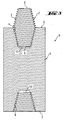
- the outer end face 8 of the integrated coaxial nipple is not a contact surface that is to be provided with a sliding layer.
- the case base 10 of the electrode is not a contact surface that is to be provided with a sliding layer.
- the end faces 6 of the nipple 2 are not contact surfaces that are to be provided with a sliding layer.
Landscapes
- Discharge Heating (AREA)
- Vertical, Hearth, Or Arc Furnaces (AREA)
- Furnace Details (AREA)
- Secondary Cells (AREA)
- Combinations Of Printed Boards (AREA)
- Lubricants (AREA)
- Image-Pickup Tubes, Image-Amplification Tubes, And Storage Tubes (AREA)
- Die Bonding (AREA)
Applications Claiming Priority (2)
| Application Number | Priority Date | Filing Date | Title |
|---|---|---|---|
| DE10253254A DE10253254B3 (de) | 2002-11-15 | 2002-11-15 | Elektrodenverbindung mit beschichteten Kontaktflächen |
| DE10253254 | 2002-11-15 |
Publications (3)
| Publication Number | Publication Date |
|---|---|
| EP1420485A2 true EP1420485A2 (de) | 2004-05-19 |
| EP1420485A3 EP1420485A3 (de) | 2005-01-12 |
| EP1420485B1 EP1420485B1 (de) | 2007-03-07 |
Family
ID=32115534
Family Applications (1)
| Application Number | Title | Priority Date | Filing Date |
|---|---|---|---|
| EP03026227A Expired - Lifetime EP1420485B1 (de) | 2002-11-15 | 2003-11-14 | Elektrodenanschluss mit beschichteter Kontaktoberfläche |
Country Status (9)
| Country | Link |
|---|---|
| US (1) | US6829287B2 (de) |
| EP (1) | EP1420485B1 (de) |
| JP (1) | JP2004172123A (de) |
| CN (1) | CN100493273C (de) |
| AT (1) | ATE356449T1 (de) |
| DE (2) | DE10253254B3 (de) |
| ES (1) | ES2285024T3 (de) |
| MX (1) | MXPA03010409A (de) |
| RU (1) | RU2335099C2 (de) |
Cited By (1)
| Publication number | Priority date | Publication date | Assignee | Title |
|---|---|---|---|---|
| EP1705751A1 (de) * | 2005-03-26 | 2006-09-27 | Jungheinrich Aktiengesellschaft | Stromanschluss für eine Leistungs- und Steuereinheit eines batteriebetriebenen Flurförderzeugs |
Families Citing this family (10)
| Publication number | Priority date | Publication date | Assignee | Title |
|---|---|---|---|---|
| DE10302956B3 (de) * | 2003-01-24 | 2004-07-22 | Sgl Carbon Ag | Kohlenstoffelektroden und deren Verbindungselemente mit gerichtet strukturierten Kontaktflächen |
| US7230969B2 (en) * | 2004-06-03 | 2007-06-12 | Ucar Carbon Company Inc. | Electrode joint locking system |
| SE532190C2 (sv) * | 2007-09-25 | 2009-11-10 | Sandvik Intellectual Property | Tilledare för elektriska motståndselement |
| RU2417564C2 (ru) * | 2009-06-03 | 2011-04-27 | Открытое акционерное общество "ЭНЕРГОПРОМ-Новочеркасский электродный завод" (ОАО "ЭПМ-НЭЗ") | Электрод для дуговой электропечи |
| RU2483215C1 (ru) * | 2011-12-16 | 2013-05-27 | Учреждение Российской академии наук Институт горного дела Дальневосточного отделения РАН (ИГД ДВО РАН) | Способ освоения месторождений руд тугоплавких металлов |
| US9068869B2 (en) * | 2013-03-14 | 2015-06-30 | Rosemount Inc. | Magnetic flowmeter with bonded PTFE electrodes |
| CN105643769A (zh) * | 2015-04-24 | 2016-06-08 | 洛阳高新永杰钨钼材料有限公司 | 一种钨电极 |
| WO2017096194A1 (en) * | 2015-12-02 | 2017-06-08 | Natural Chemistry, Inc. | Steering system for pool cleaners |
| KR102499331B1 (ko) * | 2021-03-12 | 2023-02-13 | 삼한진공개발(주) | 수직형 고정밀 진공소결로 |
| US20250212299A1 (en) * | 2023-12-21 | 2025-06-26 | Graftech International Holdings Inc. | Monitoring system for an electrode coupling device |
Family Cites Families (12)
| Publication number | Priority date | Publication date | Assignee | Title |
|---|---|---|---|---|
| US2093390A (en) * | 1934-12-19 | 1937-09-14 | Union Carbide & Carbon Corp | Means and method of making electrode joints |
| NL201029A (de) * | 1954-10-12 | 1900-01-01 | ||
| DE1565076C3 (de) * | 1965-06-30 | 1973-09-20 | Sigri Elektrographit Gmbh, 8901 Meitingen | Schraubsicherung fur eine Nippel verbindung fur Kohlenstoffelektroden |
| US3540764A (en) * | 1968-03-14 | 1970-11-17 | Union Carbide Corp | Resilient spacer for electrode joints |
| US3814828A (en) * | 1971-02-09 | 1974-06-04 | Great Lakes Carbon Corp | Nipple-electrode assembly |
| DE2330798C2 (de) * | 1973-06-16 | 1979-08-16 | C. Conradty Nuernberg Gmbh & Co Kg, 8505 Roethenbach | Graphitelektrode mit Schutzüberzug für Lichtbogenöfen |
| DE3324692A1 (de) * | 1983-07-08 | 1985-01-17 | Sigri Elektrographit Gmbh, 8901 Meitingen | Verbindung zwischen den abschnitten einer kohlenstoff- oder graphitelektrode |
| DD256899A1 (de) * | 1986-12-30 | 1988-05-25 | Waelzlager Normteile Veb | Selbstsicherndes verbindeelement |
| US5471495A (en) * | 1991-11-18 | 1995-11-28 | Voest-Alpine Industrieanlagenbeau Gmbh | Electric arc furnace arrangement for producing steel |
| FR2692748B1 (fr) * | 1992-06-18 | 1998-07-17 | Savoie Electrodes Refract | Joint de raccordement d'electrodes de four electrique. |
| RU2037984C1 (ru) * | 1992-07-14 | 1995-06-19 | Новосибирский электродный завод | Узел соединения секций электродов |
| US6500022B2 (en) * | 2001-03-30 | 2002-12-31 | Ucar Carbon Company Inc. | Threaded pin for carbon electrodes |
-
2002
- 2002-11-15 DE DE10253254A patent/DE10253254B3/de not_active Expired - Fee Related
-
2003
- 2003-11-14 ES ES03026227T patent/ES2285024T3/es not_active Expired - Lifetime
- 2003-11-14 MX MXPA03010409A patent/MXPA03010409A/es active IP Right Grant
- 2003-11-14 JP JP2003385413A patent/JP2004172123A/ja active Pending
- 2003-11-14 EP EP03026227A patent/EP1420485B1/de not_active Expired - Lifetime
- 2003-11-14 DE DE60312286T patent/DE60312286T2/de not_active Expired - Lifetime
- 2003-11-14 CN CNB2003101149867A patent/CN100493273C/zh not_active Expired - Fee Related
- 2003-11-14 RU RU2003133316/02A patent/RU2335099C2/ru not_active IP Right Cessation
- 2003-11-14 AT AT03026227T patent/ATE356449T1/de not_active IP Right Cessation
- 2003-11-17 US US10/714,984 patent/US6829287B2/en not_active Expired - Fee Related
Cited By (1)
| Publication number | Priority date | Publication date | Assignee | Title |
|---|---|---|---|---|
| EP1705751A1 (de) * | 2005-03-26 | 2006-09-27 | Jungheinrich Aktiengesellschaft | Stromanschluss für eine Leistungs- und Steuereinheit eines batteriebetriebenen Flurförderzeugs |
Also Published As
| Publication number | Publication date |
|---|---|
| CN100493273C (zh) | 2009-05-27 |
| DE10253254B3 (de) | 2004-05-27 |
| US20040097145A1 (en) | 2004-05-20 |
| CN1553748A (zh) | 2004-12-08 |
| RU2003133316A (ru) | 2005-04-20 |
| MXPA03010409A (es) | 2004-12-06 |
| US6829287B2 (en) | 2004-12-07 |
| EP1420485A3 (de) | 2005-01-12 |
| DE60312286D1 (de) | 2007-04-19 |
| DE60312286T2 (de) | 2007-12-20 |
| EP1420485B1 (de) | 2007-03-07 |
| JP2004172123A (ja) | 2004-06-17 |
| ES2285024T3 (es) | 2007-11-16 |
| RU2335099C2 (ru) | 2008-09-27 |
| ATE356449T1 (de) | 2007-03-15 |
Similar Documents
| Publication | Publication Date | Title |
|---|---|---|
| EP1420485B1 (de) | Elektrodenanschluss mit beschichteter Kontaktoberfläche | |
| EP1117504A1 (de) | Verspannschrauben für spanner mit mehreren verspannschrauben | |
| JP4267458B2 (ja) | 耐ゴーリング性被覆を有する管状部材 | |
| US4159184A (en) | Friable thread electrode joint | |
| CN101300426A (zh) | 锥形螺栓连接件以及锥形螺栓连接件的用途 | |
| US6925104B2 (en) | Carbon electrodes and connection elements of the electrodes having directionally structured contact surfaces | |
| US5577065A (en) | Device for mounting a self-baking electrode for an electric arc furnace | |
| US11365757B2 (en) | Fastener with lubricating ring for interference fitting, and assembly method using such a fastener | |
| EP3749867B1 (de) | Befestigungselement mit schmierring für presspassung und montageverfahren mit verwendung solch eines befestigungselements | |
| CA3156138C (en) | Roll connection | |
| JP3740993B2 (ja) | 管のねじ継手 | |
| US5947827A (en) | Method of reducing sliding friction of threaded rolled fasteners | |
| CZ286431B6 (en) | Electrode with automatic carbon burning | |
| JP3714138B2 (ja) | 管のねじ継手 | |
| US4162368A (en) | Assembly of furnace electrodes | |
| Balawender | The Influence of the Friction Coefficient on the Clamping Force of a Bolted Joint | |
| CN113084330A (zh) | 一种搅拌摩擦加工头 | |
| CN221426216U (zh) | 一种内孔带锥度的碳纤维抽油杆疲劳试验接头 | |
| JPH11132370A (ja) | 鋼管用ねじ継手 | |
| RU2294475C1 (ru) | Способ обработки конических резьбовых соединений труб | |
| SU1505963A1 (ru) | Смазка дл герметизации резьбовых соединений | |
| JP2992785B2 (ja) | 湿式潤滑剤類の特性測定方法 | |
| EP1728412B1 (de) | Gewindestift für kohlenstoffelektroden und elektrodenbaugrupe mit einem gewindestift | |
| RU2689459C1 (ru) | Электрододержатель | |
| RU2395178C2 (ru) | Резьбовой ниппель, угольный электрод и электродный узел |
Legal Events
| Date | Code | Title | Description |
|---|---|---|---|
| PUAI | Public reference made under article 153(3) epc to a published international application that has entered the european phase |
Free format text: ORIGINAL CODE: 0009012 |
|
| AK | Designated contracting states |
Kind code of ref document: A2 Designated state(s): AT BE BG CH CY CZ DE DK EE ES FI FR GB GR HU IE IT LI LU MC NL PT RO SE SI SK TR |
|
| AX | Request for extension of the european patent |
Extension state: AL LT LV MK |
|
| PUAL | Search report despatched |
Free format text: ORIGINAL CODE: 0009013 |
|
| AK | Designated contracting states |
Kind code of ref document: A3 Designated state(s): AT BE BG CH CY CZ DE DK EE ES FI FR GB GR HU IE IT LI LU MC NL PT RO SE SI SK TR |
|
| AX | Request for extension of the european patent |
Extension state: AL LT LV MK |
|
| 17P | Request for examination filed |
Effective date: 20050712 |
|
| AKX | Designation fees paid |
Designated state(s): AT BE BG CH CY CZ DE DK EE ES FI FR GB GR HU IE IT LI LU MC NL PT RO SE SI SK TR |
|
| GRAP | Despatch of communication of intention to grant a patent |
Free format text: ORIGINAL CODE: EPIDOSNIGR1 |
|
| GRAS | Grant fee paid |
Free format text: ORIGINAL CODE: EPIDOSNIGR3 |
|
| GRAA | (expected) grant |
Free format text: ORIGINAL CODE: 0009210 |
|
| AK | Designated contracting states |
Kind code of ref document: B1 Designated state(s): AT BE BG CH CY CZ DE DK EE ES FI FR GB GR HU IE IT LI LU MC NL PT RO SE SI SK TR |
|
| PG25 | Lapsed in a contracting state [announced via postgrant information from national office to epo] |
Ref country code: AT Free format text: LAPSE BECAUSE OF FAILURE TO SUBMIT A TRANSLATION OF THE DESCRIPTION OR TO PAY THE FEE WITHIN THE PRESCRIBED TIME-LIMIT Effective date: 20070307 Ref country code: BE Free format text: LAPSE BECAUSE OF FAILURE TO SUBMIT A TRANSLATION OF THE DESCRIPTION OR TO PAY THE FEE WITHIN THE PRESCRIBED TIME-LIMIT Effective date: 20070307 Ref country code: SI Free format text: LAPSE BECAUSE OF FAILURE TO SUBMIT A TRANSLATION OF THE DESCRIPTION OR TO PAY THE FEE WITHIN THE PRESCRIBED TIME-LIMIT Effective date: 20070307 Ref country code: LI Free format text: LAPSE BECAUSE OF FAILURE TO SUBMIT A TRANSLATION OF THE DESCRIPTION OR TO PAY THE FEE WITHIN THE PRESCRIBED TIME-LIMIT Effective date: 20070307 Ref country code: NL Free format text: LAPSE BECAUSE OF FAILURE TO SUBMIT A TRANSLATION OF THE DESCRIPTION OR TO PAY THE FEE WITHIN THE PRESCRIBED TIME-LIMIT Effective date: 20070307 Ref country code: CH Free format text: LAPSE BECAUSE OF FAILURE TO SUBMIT A TRANSLATION OF THE DESCRIPTION OR TO PAY THE FEE WITHIN THE PRESCRIBED TIME-LIMIT Effective date: 20070307 Ref country code: FI Free format text: LAPSE BECAUSE OF FAILURE TO SUBMIT A TRANSLATION OF THE DESCRIPTION OR TO PAY THE FEE WITHIN THE PRESCRIBED TIME-LIMIT Effective date: 20070307 |
|
| REG | Reference to a national code |
Ref country code: GB Ref legal event code: FG4D |
|
| REG | Reference to a national code |
Ref country code: CH Ref legal event code: EP |
|
| REF | Corresponds to: |
Ref document number: 60312286 Country of ref document: DE Date of ref document: 20070419 Kind code of ref document: P |
|
| REG | Reference to a national code |
Ref country code: IE Ref legal event code: FG4D |
|
| PG25 | Lapsed in a contracting state [announced via postgrant information from national office to epo] |
Ref country code: SE Free format text: LAPSE BECAUSE OF FAILURE TO SUBMIT A TRANSLATION OF THE DESCRIPTION OR TO PAY THE FEE WITHIN THE PRESCRIBED TIME-LIMIT Effective date: 20070607 |
|
| PG25 | Lapsed in a contracting state [announced via postgrant information from national office to epo] |
Ref country code: PT Free format text: LAPSE BECAUSE OF FAILURE TO SUBMIT A TRANSLATION OF THE DESCRIPTION OR TO PAY THE FEE WITHIN THE PRESCRIBED TIME-LIMIT Effective date: 20070807 |
|
| NLV1 | Nl: lapsed or annulled due to failure to fulfill the requirements of art. 29p and 29m of the patents act | ||
| ET | Fr: translation filed | ||
| REG | Reference to a national code |
Ref country code: CH Ref legal event code: PL |
|
| REG | Reference to a national code |
Ref country code: ES Ref legal event code: FG2A Ref document number: 2285024 Country of ref document: ES Kind code of ref document: T3 |
|
| PG25 | Lapsed in a contracting state [announced via postgrant information from national office to epo] |
Ref country code: SK Free format text: LAPSE BECAUSE OF FAILURE TO SUBMIT A TRANSLATION OF THE DESCRIPTION OR TO PAY THE FEE WITHIN THE PRESCRIBED TIME-LIMIT Effective date: 20070307 |
|
| PG25 | Lapsed in a contracting state [announced via postgrant information from national office to epo] |
Ref country code: RO Free format text: LAPSE BECAUSE OF FAILURE TO SUBMIT A TRANSLATION OF THE DESCRIPTION OR TO PAY THE FEE WITHIN THE PRESCRIBED TIME-LIMIT Effective date: 20070307 Ref country code: CZ Free format text: LAPSE BECAUSE OF FAILURE TO SUBMIT A TRANSLATION OF THE DESCRIPTION OR TO PAY THE FEE WITHIN THE PRESCRIBED TIME-LIMIT Effective date: 20070307 |
|
| PLBE | No opposition filed within time limit |
Free format text: ORIGINAL CODE: 0009261 |
|
| STAA | Information on the status of an ep patent application or granted ep patent |
Free format text: STATUS: NO OPPOSITION FILED WITHIN TIME LIMIT |
|
| PG25 | Lapsed in a contracting state [announced via postgrant information from national office to epo] |
Ref country code: DK Free format text: LAPSE BECAUSE OF FAILURE TO SUBMIT A TRANSLATION OF THE DESCRIPTION OR TO PAY THE FEE WITHIN THE PRESCRIBED TIME-LIMIT Effective date: 20070307 |
|
| 26N | No opposition filed |
Effective date: 20071210 |
|
| PG25 | Lapsed in a contracting state [announced via postgrant information from national office to epo] |
Ref country code: IT Free format text: LAPSE BECAUSE OF FAILURE TO SUBMIT A TRANSLATION OF THE DESCRIPTION OR TO PAY THE FEE WITHIN THE PRESCRIBED TIME-LIMIT Effective date: 20070307 Ref country code: GR Free format text: LAPSE BECAUSE OF FAILURE TO SUBMIT A TRANSLATION OF THE DESCRIPTION OR TO PAY THE FEE WITHIN THE PRESCRIBED TIME-LIMIT Effective date: 20070608 |
|
| PG25 | Lapsed in a contracting state [announced via postgrant information from national office to epo] |
Ref country code: MC Free format text: LAPSE BECAUSE OF NON-PAYMENT OF DUE FEES Effective date: 20071130 |
|
| GBPC | Gb: european patent ceased through non-payment of renewal fee |
Effective date: 20071114 |
|
| PG25 | Lapsed in a contracting state [announced via postgrant information from national office to epo] |
Ref country code: IE Free format text: LAPSE BECAUSE OF NON-PAYMENT OF DUE FEES Effective date: 20071114 |
|
| PG25 | Lapsed in a contracting state [announced via postgrant information from national office to epo] |
Ref country code: GB Free format text: LAPSE BECAUSE OF NON-PAYMENT OF DUE FEES Effective date: 20071114 |
|
| PG25 | Lapsed in a contracting state [announced via postgrant information from national office to epo] |
Ref country code: EE Free format text: LAPSE BECAUSE OF FAILURE TO SUBMIT A TRANSLATION OF THE DESCRIPTION OR TO PAY THE FEE WITHIN THE PRESCRIBED TIME-LIMIT Effective date: 20070307 |
|
| PG25 | Lapsed in a contracting state [announced via postgrant information from national office to epo] |
Ref country code: CY Free format text: LAPSE BECAUSE OF FAILURE TO SUBMIT A TRANSLATION OF THE DESCRIPTION OR TO PAY THE FEE WITHIN THE PRESCRIBED TIME-LIMIT Effective date: 20070307 |
|
| PG25 | Lapsed in a contracting state [announced via postgrant information from national office to epo] |
Ref country code: BG Free format text: LAPSE BECAUSE OF FAILURE TO SUBMIT A TRANSLATION OF THE DESCRIPTION OR TO PAY THE FEE WITHIN THE PRESCRIBED TIME-LIMIT Effective date: 20070607 Ref country code: LU Free format text: LAPSE BECAUSE OF NON-PAYMENT OF DUE FEES Effective date: 20071114 |
|
| PG25 | Lapsed in a contracting state [announced via postgrant information from national office to epo] |
Ref country code: HU Free format text: LAPSE BECAUSE OF FAILURE TO SUBMIT A TRANSLATION OF THE DESCRIPTION OR TO PAY THE FEE WITHIN THE PRESCRIBED TIME-LIMIT Effective date: 20070908 Ref country code: TR Free format text: LAPSE BECAUSE OF FAILURE TO SUBMIT A TRANSLATION OF THE DESCRIPTION OR TO PAY THE FEE WITHIN THE PRESCRIBED TIME-LIMIT Effective date: 20070307 |
|
| PGFP | Annual fee paid to national office [announced via postgrant information from national office to epo] |
Ref country code: ES Payment date: 20091123 Year of fee payment: 7 |
|
| PGFP | Annual fee paid to national office [announced via postgrant information from national office to epo] |
Ref country code: FR Payment date: 20091201 Year of fee payment: 7 |
|
| PGFP | Annual fee paid to national office [announced via postgrant information from national office to epo] |
Ref country code: DE Payment date: 20101130 Year of fee payment: 8 |
|
| REG | Reference to a national code |
Ref country code: FR Ref legal event code: ST Effective date: 20110801 |
|
| PG25 | Lapsed in a contracting state [announced via postgrant information from national office to epo] |
Ref country code: FR Free format text: LAPSE BECAUSE OF NON-PAYMENT OF DUE FEES Effective date: 20101130 |
|
| REG | Reference to a national code |
Ref country code: ES Ref legal event code: FD2A Effective date: 20120110 |
|
| PG25 | Lapsed in a contracting state [announced via postgrant information from national office to epo] |
Ref country code: ES Free format text: LAPSE BECAUSE OF NON-PAYMENT OF DUE FEES Effective date: 20101115 |
|
| REG | Reference to a national code |
Ref country code: DE Ref legal event code: R119 Ref document number: 60312286 Country of ref document: DE Effective date: 20120601 |
|
| PG25 | Lapsed in a contracting state [announced via postgrant information from national office to epo] |
Ref country code: DE Free format text: LAPSE BECAUSE OF NON-PAYMENT OF DUE FEES Effective date: 20120601 |