EP1420498A1 - Assemblage de stator d'une machine électrique et méthode de production du même - Google Patents
Assemblage de stator d'une machine électrique et méthode de production du même Download PDFInfo
- Publication number
- EP1420498A1 EP1420498A1 EP02025705A EP02025705A EP1420498A1 EP 1420498 A1 EP1420498 A1 EP 1420498A1 EP 02025705 A EP02025705 A EP 02025705A EP 02025705 A EP02025705 A EP 02025705A EP 1420498 A1 EP1420498 A1 EP 1420498A1
- Authority
- EP
- European Patent Office
- Prior art keywords
- stator
- stator assembly
- teeth
- bent
- tooth
- Prior art date
- Legal status (The legal status is an assumption and is not a legal conclusion. Google has not performed a legal analysis and makes no representation as to the accuracy of the status listed.)
- Granted
Links
- 238000004519 manufacturing process Methods 0.000 title claims description 8
- 239000002184 metal Substances 0.000 claims abstract description 42
- 229910052751 metal Inorganic materials 0.000 claims abstract description 42
- 238000004804 winding Methods 0.000 claims description 14
- 238000000034 method Methods 0.000 claims description 9
- 238000005452 bending Methods 0.000 claims description 6
- 238000009423 ventilation Methods 0.000 description 8
- 238000001816 cooling Methods 0.000 description 6
- 238000005520 cutting process Methods 0.000 description 4
- 150000002739 metals Chemical class 0.000 description 3
- 239000002699 waste material Substances 0.000 description 2
- 238000004026 adhesive bonding Methods 0.000 description 1
- 238000009826 distribution Methods 0.000 description 1
- 230000004907 flux Effects 0.000 description 1
- 238000005304 joining Methods 0.000 description 1
- 238000003466 welding Methods 0.000 description 1
Images




Classifications
-
- H—ELECTRICITY
- H02—GENERATION; CONVERSION OR DISTRIBUTION OF ELECTRIC POWER
- H02K—DYNAMO-ELECTRIC MACHINES
- H02K1/00—Details of the magnetic circuit
- H02K1/06—Details of the magnetic circuit characterised by the shape, form or construction
- H02K1/12—Stationary parts of the magnetic circuit
- H02K1/14—Stator cores with salient poles
- H02K1/141—Stator cores with salient poles consisting of C-shaped cores
-
- H—ELECTRICITY
- H02—GENERATION; CONVERSION OR DISTRIBUTION OF ELECTRIC POWER
- H02K—DYNAMO-ELECTRIC MACHINES
- H02K1/00—Details of the magnetic circuit
- H02K1/06—Details of the magnetic circuit characterised by the shape, form or construction
- H02K1/12—Stationary parts of the magnetic circuit
- H02K1/14—Stator cores with salient poles
- H02K1/146—Stator cores with salient poles consisting of a generally annular yoke with salient poles
-
- H—ELECTRICITY
- H02—GENERATION; CONVERSION OR DISTRIBUTION OF ELECTRIC POWER
- H02K—DYNAMO-ELECTRIC MACHINES
- H02K1/00—Details of the magnetic circuit
- H02K1/06—Details of the magnetic circuit characterised by the shape, form or construction
- H02K1/12—Stationary parts of the magnetic circuit
- H02K1/14—Stator cores with salient poles
- H02K1/146—Stator cores with salient poles consisting of a generally annular yoke with salient poles
- H02K1/148—Sectional cores
Definitions
- the present invention relates to a stator assembly for an electrical machine and a method of manufacturing a stator assembly.
- Permanent Magnet Permanent Magnet
- the present invention in general, can be used in any type of rotational electrical machines.
- Electrical machines having an inner rotor configuration include a stator assembly which is mounted on the rotor shaft and one or more permanent magnets as well as a stator assembly, such as a stator laminated from a number of metal sheets, comprising phase windings.
- the rotor assembly is coaxially inserted into the stator assembly.
- the stator assembly surrounds the stator.
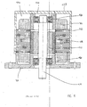
- Fig. 8 schematically shows the general design of an electrical machine, comprising a housing 114, in which are included the stator assembly 118, the stator assembly 116 as well as bearing 126, 128 for rotatably supporting the stator assembly.
- the stator assembly 118 comprises sheet metals 155 and phase windings 160 and defines an interior cavity into which the stator assembly 116 can be inserted.
- the stator assembly 116 includes the shaft 110, a yoke 112 and permanent magnets 122.
- the bearings 126, 128 for the stator assembly can be integrated into a flange 124 of the motor housing 114.
- the present invention relates to a stator assembly for an electrical machine comprising a number of metal sheets arranged on top of each other to form a layered structure and a method of manufacturing such a stator assembly.
- stator body from a number of metal sheets, stamped to have a shape corresponding to the cross section of the stator core and laminated on top of each other in the axial direction of the stator core.
- a stator core laminated from a number of sheet metals is able to provide a good, even current distribution through the stator core, reducing eddy currents.
- stator core having stator segments, each segment comprising one stator tooth
- each segment of the stator can be configured to receive a pre-wound coil on a respective tooth or pole. Only after providing the coils on the respective teeth or poles of the stator segments, these stator segments are interconnected in series and are arranged to form one annular stator.
- designing a stator core from a plurality of separate stator segments facilitates the winding technique for providing the phase windings on the stator body.
- stator core When manufacturing a stator core from laminated sheet metal, as a whole or by providing a number of separate stator segments, the layers of the stator core are stamped from a metal sheet in a way that a relatively large amount of waste material is created due to the particular shape of the stator sheets.
- a simple method of stator core manufacturing and stator winding shall be proposed.
- stator assembly for an electrical machine comprising the features of claim 1 and a method of manufacturing a stator assembly according to claim 13.
- the stator assembly comprises at least one, and preferably a number of metal sheets, in particular metal bands, arranged on top of each other to form a layered structure.
- the one or more layers of said structure extend in a direction which is generally parallel to a longitudinal axis of the final stator assembly, wherein the layered structure is bent to form at least one sector of a stator.
- the difference between the present invention and the laminated stator cores of the prior art is that, according to the present invention, the one or more layers of the layered structure extend parallel to longitudinal axis of the stator assembly wherein, in the prior art, each layer extends perpendicular to the longitudinal axis of the stator core.
- stator core or stator body By manufacturing the stator core or stator body from a number of laminated metal bands a number of advantages arise. When stamping the metal bands from sheet metal, due to the simple geometry of the metal bands, hardly any waste material will be created. Further, the stator core can be manufactured easily by arranging the laminated band structure parallel to the longitudinal axis of the stator assembly and bending said laminated band structure to have the shape of stator teeth and connecting sections between said stator teeth.
- the structure which is bend from the laminated metal bands can be either a stator segment comprising one or more stator teeth or poles and connecting sections therebetween or can be a series of stator teeth comprising a larger fraction or all of the teeth of the final stator assembly.
- the series of stator teeth can be arranged in a straight line first before the metal band is bent to have the shape of a closed stator ring. Further, the teeth of the bent stator structure may receive phase windings, such as pre-wound coils or individual windings before the stator teeth are joined to form one closed stator ring.
- a further advantage of the present invention arises from the fact that the layered structure formed from the laminated metal bands can be bent to form stator teeth including a longitudinal gap in the interior of each tooth. This gap can be used as a ventilation channel for cooling the stator teeth. As high temperatures are created in the area of the phase windings surrounding the stator teeth, cooling the stator in this region can be particularly advantageous.
- a thermal sensor can be provided in the gap for sensing the stator temperature during operation.
- the thermal sensor can be connected to an electronic circuit for controlling the stator temperature.
- the layers of said layered structure are joined at their edges with a neighboring layered structure in an interlacing manner.
- stator core formed from the layered structure can be surrounded by a second layered structure comprising one or more metal bands and forming a yoke.
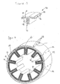
- Fig. 1 schematically shows a perspective view of a stator assembly according the present invention, forming a stator core.
- the stator assembly 10 shown in Fig. 1 is formed from three metal bands 12, 14, 16 which are arranged on top of each other to form a layered structure 18. The layers are laminated on top of each other and are connected e.g. by welding, glueing or application of rivets.
- stator assembly is formed from a layered structure, comprising a number of metal bands 12, 14, 16, it is also possible to construct the stator assembly according to the present invention from just one metal band, suitably bent to form the stator assembly, as described below.
- the layers 12, 14, 16 of the layered structure 18 extend in a direction which is generally parallel to a longitudinal axis 20 of the stator assembly 10.
- the layered structure 18 is bent to form teeth, or poles, 22, 24, 26, 28, 30, 32, 34, 36 and 38 of the stator core as well as connecting sections, such as 40, 42 between the stator teeth.
- the layered structure 18 is joined at it ends 44 to form a closed stator core.
- the layers 12, 14, 16 of the layered structure 18 are not aligned at the ends 44 to join one end of the layered structure with a neighboring end in an interlacing manner.
- stator teeth or poles 22 to 38 and connecting sections, such as 40, 42 are formed wherein a gap, such as 46, 48 is created in each tooth 22 to 38 which can be used as a ventilation channel.
- holes 50 are provided for connecting this end 44 with a neighboring end of the layered structure, e.g. by rivets, screws or the like.
- any other type of suitable connection can be used for joining the structure of the stator assembly.
- Fig. 2 shows the closed ring structure of Fig. 1, connected at the ends 44 of the layered structure 18 which is fixedly connected e.g. by rivets 52.
- the stator core formed from the layered structure 18 is surrounded by a second layered structure 54, formed from three metal bands 56, 58, 60, forming a yoke of the stator assembly 10.
- the yoke formed from the second layered structure 54 comprises circular metal sheet bands. It serves for redirecting the magnetic flux.
- the gap 46, 48 within the stator teeth remains open to the outside, even when the stator core is surrounded by the second layered structure 54 forming the yoke. Accordingly, the gap 46, 48 can serve as a in-tooth ventilation channel for cooling the stator during operation.
- a thermal sensor (not shown) can be provided in the gap 46, 48.
- the output of the thermal sensor can be provided to an electronic unit for controlling the stator temperature. This embodiment is particularly useful for a motor having a cooling fan or another type of cooling means for controlling the motor temperature.
- Fig. 3 shows a schematic perspective view of a stator segment for forming a stator assembly according to a second embodiment of the invention.
- the stator segment 62 is formed from three metal bands 64, 66, 68 which are bent to form one stator tooth 70 having a ventilation gap 72.
- the three metal bands 64, 66, 68 are arranged in an overlapping manner at each end 74 of the stator segment 62 so that they do not abut but can be joined to a neighboring stator segment in an interlacing manner.
- holes 76 are provided for connecting the stator segment 62 with a neighboring stator segment.
- Fig. 4 shows the stator assembly according to the present invention which is constructed from a number of stator segments 62 as shown in fig. 3.
- the stator assembly of fig. 4 comprises nine stator segments, e.g. 62, which are connected with neighboring stator segments, such as 78, 80, in an interlacing manner, as indicated at 82, to form a closed stator ring.
- the closed ring structure comprising nine stator segments 62, 78, 80, etc, is surrounded by a second layered structure 54, formed form three metal bands 56, 58, 60, forming a yoke of the stator assembly, as in the embodiment of fig. 2.
- each stator segment 62 can be provided with a pre-wound coil (not shown), before the stator segments, 62, 78, 80, etc., are joined at their ends, e.g. 74, for forming the closed stator ring. Subsequently, the separate pre-wound coils, located on the stator teeth, are appropriately connected.
- This embodiment enables a particularly simple winding technique.
- the stator assembly is manufactured by first bending the stator teeth 22, 24, 26, etc., to be arranged in a straight line; subsequently, the coil windings are provided on the stator teeth; and only after the coil windings have been wound on the stator teeth, the layered structure 18 is bent to form a closed stator core.
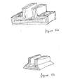
- Fig. 5a, 5b, 5c, 5d, 5e and 5f illustrate possible shapes of tooth tips which can be realized with the present invention.
- Fig. 6 shows a schematic sectional view through part of a stator assembly formed from a plurality of stator segments and including a yoke surrounding the stator core.
- the stator assembly of fig. 6 comprises a stator core formed from a first layer structure 18 comprising metal bands 12, 14, 16 which are bent to form stator teeth or poles 22, 24.
- the stator teeth or poles 22, 24 are bent in a way that a gap 46, 48 is created in each tooth 22, 24 which can be used as a ventilation channel.
- the stator core is surrounded by a second layer structure 84, formed from three metal bands 86, 88, 90 to form a yoke of the stator assembly.
- the second layered structure 84 is formed to provide additional ventilation channels 92, 94 opposite the gaps 46, 48 in the stator teeth 22, 44 for improving the overall cooling efficiency of the stator during operation.
- Fig. 7a and 7b show further embodiments of the stator assembly according to the present invention for improving the eddy current behavior.
- the stator core is formed by bending the layered structure 18 basically as shown in fig. 1 and subsequently cutting of the tips 96 of the stator teeth 22, 24.
- a cutting line is schematically indicated at 98.
- the design of fig. 7a improves the eddy current behavior of the stator assembly in the pole shoe zone.
- Fig. 7b shows a further embodiment of the stator assembly according to the present invention.
- the layered structure 18 is formed from three metal bands as shown in fig. 7a, formed by bending the layered structure and cutting off the tips of the stator teeth 22, 24 as explained above.
- 16 small slots 100 are provided in the section 102 bridging to stator teeth 22, 24.
- the slots preferably have a length of less than 0,2 mm.
- the design of fig. 7b helps to improve the eddy current behavior in the back yoke zone.
Landscapes
- Engineering & Computer Science (AREA)
- Power Engineering (AREA)
- Iron Core Of Rotating Electric Machines (AREA)
Priority Applications (2)
| Application Number | Priority Date | Filing Date | Title |
|---|---|---|---|
| EP20020025705 EP1420498B1 (fr) | 2002-11-15 | 2002-11-15 | Assemblage de stator d'une machine électrique et méthode de production du même |
| DE2002612405 DE60212405T2 (de) | 2002-11-15 | 2002-11-15 | Ständeraufbau für eine elektrische Maschine und Herstellungsverfahren für denselben |
Applications Claiming Priority (1)
| Application Number | Priority Date | Filing Date | Title |
|---|---|---|---|
| EP20020025705 EP1420498B1 (fr) | 2002-11-15 | 2002-11-15 | Assemblage de stator d'une machine électrique et méthode de production du même |
Publications (2)
| Publication Number | Publication Date |
|---|---|
| EP1420498A1 true EP1420498A1 (fr) | 2004-05-19 |
| EP1420498B1 EP1420498B1 (fr) | 2006-06-14 |
Family
ID=32116265
Family Applications (1)
| Application Number | Title | Priority Date | Filing Date |
|---|---|---|---|
| EP20020025705 Expired - Lifetime EP1420498B1 (fr) | 2002-11-15 | 2002-11-15 | Assemblage de stator d'une machine électrique et méthode de production du même |
Country Status (2)
| Country | Link |
|---|---|
| EP (1) | EP1420498B1 (fr) |
| DE (1) | DE60212405T2 (fr) |
Cited By (10)
| Publication number | Priority date | Publication date | Assignee | Title |
|---|---|---|---|---|
| DE102004013869A1 (de) * | 2004-03-20 | 2005-10-06 | Krebs & Aulich Gmbh | Bandgesetzter Magnetkörper einer elektrischen Maschine |
| EP2149961A1 (fr) | 2008-07-30 | 2010-02-03 | Askoll Holding S.r.l. | Procédé pour la fabrication d'un stator de moteur électrique, stator et moteur électrique |
| CN103354405A (zh) * | 2009-06-19 | 2013-10-16 | 建准电机工业股份有限公司 | 马达定子的制造方法 |
| JP2014003813A (ja) * | 2012-06-19 | 2014-01-09 | Akira Miyoshi | 回転電気機器 |
| JP2015130796A (ja) * | 2015-03-02 | 2015-07-16 | 章 三好 | 回転電気機器 |
| EP2652860A4 (fr) * | 2010-12-13 | 2015-09-02 | Radam Motors Llc | Stator utilisé dans un moteur ou un générateur électrique comportant un matériau magnétique à faible perte et procédé de fabrication d'un stator |
| US9354422B1 (en) * | 2013-07-01 | 2016-05-31 | Ball Aerospace & Technologies Corp. | High acceleration actuator |
| CN110011435A (zh) * | 2019-03-12 | 2019-07-12 | 浙江实日机电科技有限公司 | 一种定子铁芯及其装配设备 |
| US10637390B1 (en) | 2016-11-16 | 2020-04-28 | Ball Aerospace & Technologies Corp. | Analog switching current drive |
| DE102019203883A1 (de) * | 2019-03-21 | 2020-09-24 | Robert Bosch Gmbh | Ringförmiger Stator und Verfahren zu seiner Herstellung |
Families Citing this family (1)
| Publication number | Priority date | Publication date | Assignee | Title |
|---|---|---|---|---|
| DE202013005481U1 (de) * | 2013-06-19 | 2014-09-22 | BROSE SCHLIEßSYSTEME GMBH & CO. KG | Polgehäuse für einen Elektromotor |
Citations (5)
| Publication number | Priority date | Publication date | Assignee | Title |
|---|---|---|---|---|
| DE534319C (de) * | 1924-12-16 | 1931-09-24 | Eduard Uller | Elektrischer Stromerzeuger |
| US3983435A (en) * | 1974-11-05 | 1976-09-28 | General Electric Company | Stator assembly formed of flat, strip material |
| US4546282A (en) * | 1982-06-29 | 1985-10-08 | Institut Cerac S.A. | Magnetizable core for accommodating electrical conductors in an electrical machine, and a method of manufacturing such a core |
| JPH10214740A (ja) * | 1997-01-30 | 1998-08-11 | Toshiba Fa Syst Eng Kk | 巻鉄心の開脚装置及び巻鉄心形誘導機器の製造方法 |
| JP2000184682A (ja) * | 1998-12-10 | 2000-06-30 | Mitsubishi Electric Corp | ステータコアおよびその製造方法 |
-
2002
- 2002-11-15 EP EP20020025705 patent/EP1420498B1/fr not_active Expired - Lifetime
- 2002-11-15 DE DE2002612405 patent/DE60212405T2/de not_active Expired - Fee Related
Patent Citations (5)
| Publication number | Priority date | Publication date | Assignee | Title |
|---|---|---|---|---|
| DE534319C (de) * | 1924-12-16 | 1931-09-24 | Eduard Uller | Elektrischer Stromerzeuger |
| US3983435A (en) * | 1974-11-05 | 1976-09-28 | General Electric Company | Stator assembly formed of flat, strip material |
| US4546282A (en) * | 1982-06-29 | 1985-10-08 | Institut Cerac S.A. | Magnetizable core for accommodating electrical conductors in an electrical machine, and a method of manufacturing such a core |
| JPH10214740A (ja) * | 1997-01-30 | 1998-08-11 | Toshiba Fa Syst Eng Kk | 巻鉄心の開脚装置及び巻鉄心形誘導機器の製造方法 |
| JP2000184682A (ja) * | 1998-12-10 | 2000-06-30 | Mitsubishi Electric Corp | ステータコアおよびその製造方法 |
Non-Patent Citations (2)
| Title |
|---|
| PATENT ABSTRACTS OF JAPAN vol. 1998, no. 13 30 November 1998 (1998-11-30) * |
| PATENT ABSTRACTS OF JAPAN vol. 2000, no. 09 13 October 2000 (2000-10-13) * |
Cited By (14)
| Publication number | Priority date | Publication date | Assignee | Title |
|---|---|---|---|---|
| DE102004013869A1 (de) * | 2004-03-20 | 2005-10-06 | Krebs & Aulich Gmbh | Bandgesetzter Magnetkörper einer elektrischen Maschine |
| CN101640458B (zh) * | 2008-07-30 | 2014-02-19 | 艾斯科尔侯丁有限公司 | 电动机定子和电动机的制造过程,定子及电动机 |
| EP2149961A1 (fr) | 2008-07-30 | 2010-02-03 | Askoll Holding S.r.l. | Procédé pour la fabrication d'un stator de moteur électrique, stator et moteur électrique |
| US8127428B2 (en) | 2008-07-30 | 2012-03-06 | Askoll Holding S.R.L. | Proceeding for the manufacturing of a stator for an electric motor and of an electric motor |
| CN103354405B (zh) * | 2009-06-19 | 2016-04-06 | 建准电机工业股份有限公司 | 马达定子的制造方法 |
| CN103354406B (zh) * | 2009-06-19 | 2015-09-02 | 建准电机工业股份有限公司 | 马达定子的制造方法 |
| CN103354405A (zh) * | 2009-06-19 | 2013-10-16 | 建准电机工业股份有限公司 | 马达定子的制造方法 |
| EP2652860A4 (fr) * | 2010-12-13 | 2015-09-02 | Radam Motors Llc | Stator utilisé dans un moteur ou un générateur électrique comportant un matériau magnétique à faible perte et procédé de fabrication d'un stator |
| JP2014003813A (ja) * | 2012-06-19 | 2014-01-09 | Akira Miyoshi | 回転電気機器 |
| US9354422B1 (en) * | 2013-07-01 | 2016-05-31 | Ball Aerospace & Technologies Corp. | High acceleration actuator |
| JP2015130796A (ja) * | 2015-03-02 | 2015-07-16 | 章 三好 | 回転電気機器 |
| US10637390B1 (en) | 2016-11-16 | 2020-04-28 | Ball Aerospace & Technologies Corp. | Analog switching current drive |
| CN110011435A (zh) * | 2019-03-12 | 2019-07-12 | 浙江实日机电科技有限公司 | 一种定子铁芯及其装配设备 |
| DE102019203883A1 (de) * | 2019-03-21 | 2020-09-24 | Robert Bosch Gmbh | Ringförmiger Stator und Verfahren zu seiner Herstellung |
Also Published As
| Publication number | Publication date |
|---|---|
| EP1420498B1 (fr) | 2006-06-14 |
| DE60212405D1 (de) | 2006-07-27 |
| DE60212405T2 (de) | 2007-02-01 |
Similar Documents
| Publication | Publication Date | Title |
|---|---|---|
| CA2337042C (fr) | Stator a dents formees dans un materiau magnetique doux en poudre | |
| EP1766757B1 (fr) | Noyau statorique de machine electrodynamique, a mini capuchons | |
| US6768239B1 (en) | Electromotive devices using notched ribbon windings | |
| US20040155548A1 (en) | Transverse flux machine with stator made of e-shaped laminates | |
| US20040207284A1 (en) | Stator assembly including a core slot insert member | |
| US11411452B2 (en) | Coil and motor using same | |
| SE512783C2 (sv) | Statoraggregat för en elektrisk maskin | |
| EP1420498B1 (fr) | Assemblage de stator d'une machine électrique et méthode de production du même | |
| JP2003299329A (ja) | 回転電機 | |
| CN114128091A (zh) | 线圈、定子、及电动机 | |
| US6365999B1 (en) | Stator module for an electric motor | |
| EP1722458A1 (fr) | Armature d'induit pour machine dynamoelectrique | |
| JP3928297B2 (ja) | 電動機及びその製造方法 | |
| JP3816789B2 (ja) | 回転磁界型電動機の固定子及びその製造方法 | |
| US6992418B2 (en) | Stator component for an inner rotor DC motor | |
| EP0343845A2 (fr) | Machines électriques | |
| JP4182129B2 (ja) | 電気機械のステータ | |
| CN103026584A (zh) | 电机的用于减少涡流的绕组齿和组件 | |
| CN101087075A (zh) | 定子部段及其装配方法 | |
| KR0140467B1 (ko) | 회전 전기기계의 회전자 및 그 제조방법 | |
| JP4432869B2 (ja) | 回転電機 | |
| JP2003009477A (ja) | 永久磁石式回転電機の回転子構造 | |
| JPH08237891A (ja) | 回転電機の固定子鉄心 | |
| JPH11346446A (ja) | 回転電機の固定子 | |
| CN111092531A (zh) | 电动机和使用它的电动风机、电动吸尘器 |
Legal Events
| Date | Code | Title | Description |
|---|---|---|---|
| PUAI | Public reference made under article 153(3) epc to a published international application that has entered the european phase |
Free format text: ORIGINAL CODE: 0009012 |
|
| AK | Designated contracting states |
Kind code of ref document: A1 Designated state(s): AT BE BG CH CY CZ DE DK EE ES FI FR GB GR IE IT LI LU MC NL PT SE SK TR |
|
| AX | Request for extension of the european patent |
Extension state: AL LT LV MK RO SI |
|
| 17P | Request for examination filed |
Effective date: 20040730 |
|
| 17Q | First examination report despatched |
Effective date: 20041124 |
|
| AKX | Designation fees paid |
Designated state(s): DE FR IT |
|
| GRAP | Despatch of communication of intention to grant a patent |
Free format text: ORIGINAL CODE: EPIDOSNIGR1 |
|
| GRAC | Information related to communication of intention to grant a patent modified |
Free format text: ORIGINAL CODE: EPIDOSCIGR1 |
|
| GRAS | Grant fee paid |
Free format text: ORIGINAL CODE: EPIDOSNIGR3 |
|
| GRAA | (expected) grant |
Free format text: ORIGINAL CODE: 0009210 |
|
| AK | Designated contracting states |
Kind code of ref document: B1 Designated state(s): DE FR IT |
|
| PG25 | Lapsed in a contracting state [announced via postgrant information from national office to epo] |
Ref country code: IT Free format text: LAPSE BECAUSE OF FAILURE TO SUBMIT A TRANSLATION OF THE DESCRIPTION OR TO PAY THE FEE WITHIN THE PRESCRIBED TIME-LIMIT;WARNING: LAPSES OF ITALIAN PATENTS WITH EFFECTIVE DATE BEFORE 2007 MAY HAVE OCCURRED AT ANY TIME BEFORE 2007. THE CORRECT EFFECTIVE DATE MAY BE DIFFERENT FROM THE ONE RECORDED. Effective date: 20060614 |
|
| REF | Corresponds to: |
Ref document number: 60212405 Country of ref document: DE Date of ref document: 20060727 Kind code of ref document: P |
|
| PLBE | No opposition filed within time limit |
Free format text: ORIGINAL CODE: 0009261 |
|
| STAA | Information on the status of an ep patent application or granted ep patent |
Free format text: STATUS: NO OPPOSITION FILED WITHIN TIME LIMIT |
|
| EN | Fr: translation not filed | ||
| 26N | No opposition filed |
Effective date: 20070315 |
|
| PGFP | Annual fee paid to national office [announced via postgrant information from national office to epo] |
Ref country code: DE Payment date: 20071127 Year of fee payment: 6 |
|
| PG25 | Lapsed in a contracting state [announced via postgrant information from national office to epo] |
Ref country code: FR Free format text: LAPSE BECAUSE OF FAILURE TO SUBMIT A TRANSLATION OF THE DESCRIPTION OR TO PAY THE FEE WITHIN THE PRESCRIBED TIME-LIMIT Effective date: 20070309 |
|
| PG25 | Lapsed in a contracting state [announced via postgrant information from national office to epo] |
Ref country code: FR Free format text: LAPSE BECAUSE OF FAILURE TO SUBMIT A TRANSLATION OF THE DESCRIPTION OR TO PAY THE FEE WITHIN THE PRESCRIBED TIME-LIMIT Effective date: 20060614 |
|
| PG25 | Lapsed in a contracting state [announced via postgrant information from national office to epo] |
Ref country code: DE Free format text: LAPSE BECAUSE OF NON-PAYMENT OF DUE FEES Effective date: 20090603 |