EP1420522A1 - Système de configuration de dispositifs de réseau et procédé de reconfiguration de dispositifs - Google Patents
Système de configuration de dispositifs de réseau et procédé de reconfiguration de dispositifs Download PDFInfo
- Publication number
- EP1420522A1 EP1420522A1 EP02405983A EP02405983A EP1420522A1 EP 1420522 A1 EP1420522 A1 EP 1420522A1 EP 02405983 A EP02405983 A EP 02405983A EP 02405983 A EP02405983 A EP 02405983A EP 1420522 A1 EP1420522 A1 EP 1420522A1
- Authority
- EP
- European Patent Office
- Prior art keywords
- configuration
- configuration information
- current
- information
- new
- Prior art date
- Legal status (The legal status is an assumption and is not a legal conclusion. Google has not performed a legal analysis and makes no representation as to the accuracy of the status listed.)
- Granted
Links
Images
Classifications
-
- H—ELECTRICITY
- H04—ELECTRIC COMMUNICATION TECHNIQUE
- H04B—TRANSMISSION
- H04B3/00—Line transmission systems
- H04B3/54—Systems for transmission via power distribution lines
-
- H—ELECTRICITY
- H04—ELECTRIC COMMUNICATION TECHNIQUE
- H04B—TRANSMISSION
- H04B2203/00—Indexing scheme relating to line transmission systems
- H04B2203/54—Aspects of powerline communications not already covered by H04B3/54 and its subgroups
- H04B2203/5429—Applications for powerline communications
- H04B2203/5445—Local network
-
- H—ELECTRICITY
- H04—ELECTRIC COMMUNICATION TECHNIQUE
- H04B—TRANSMISSION
- H04B2203/00—Indexing scheme relating to line transmission systems
- H04B2203/54—Aspects of powerline communications not already covered by H04B3/54 and its subgroups
- H04B2203/5429—Applications for powerline communications
- H04B2203/5458—Monitor sensor; Alarm systems
Definitions
- the invention is based on a configuration system Configuring devices on networks and a method for Reconfigure directed such devices.
- a configuration system Configuring devices on networks and a method for Reconfigure directed such devices.
- the used coming intelligent electronic devices are mostly Universal devices for a wide variety of uses can be used and can therefore be configured as required are. This is usually done with the help of a control program, that can access hardware ports, which then for example switches or sensors in a predetermined manner operate, influence, read out etc. With yourself changing conditions for the operation of the devices can cause this be reconfigured. This usually happens either by the manufacturers of the devices or by Maintenance company that specializes in such devices to have.
- Configurations of devices are currently only made on site, which means immediately on reconfiguring device.
- the reason for this is that the configurators generally do not have sufficient knowledge about type, model or current configuration of one reconfiguring device and therefore rely on it are, first of all, a current, therefore functional Establish configuration before adjusting accordingly Configuration changes that affect the Do not override the functionality of the device, can be carried out.
- This procedure is labor-intensive and often requires long travel times and thus high personnel costs for the maintenance technicians on site. It would be desirable and is therefore the task of the present one Invention, a reconfiguration of the devices also over to be able to make the network with which these devices connected anyway without an on-site reconfiguration must be carried out.
- the invention is initially based on a configuration system Configuration of devices in networks directed with at least one device to be configured with elements that are configured in a specific way and Configuration means for reconfiguring the device on hand received reconfiguration information; and a configuration server that with the at least one too configuring device is connected via a network, and which has means of composition for creating a new one Configuration information for the device to be configured and means for determining the current configuration of the at least one device to be configured.
- the device to be configured can do anything be configurable device, which has an external effect Switching states, for example, special intelligent electronic devices in control and system engineering or data processing systems with built-in Control functionality etc.
- the elements which can be configured set the hardware and Software components that give the device the outside convey acting properties. You can for example switches, sensors, actuators, but also internal ones Software objects such as logging programs or Timing controls.
- the current configuration information is not just one Configuration of software and / or remote controlled configurable elements, but also includes Configuration information regarding items that are only available through manual intervention can be configured.
- Such elements are for example hardware components of control devices and especially primary devices that are configured by the Device can be controlled. Such elements cannot automatically based on the new configuration information be reconfigured; the new configuration information therefore reflects the such elements current configuration.
- the device to be configured at least has a configuration means, which the actual Can generate configuration.
- configuration is the entirety of States of the device that an outward unfolding Show effects.
- a configuration information is in contrast, coded information, for example one Text file, which in a certain formatting prepared, represents a configuration of the device.
- coded information for example one Text file, which in a certain formatting prepared, represents a configuration of the device.
- SCL file Substation Configuration Language
- the Configuration means generated by setting up appropriate Software and / or hardware components of the device using the configuration information the configuration actually present in the device.
- the Hardware components are set up e.g. by configure logical links in an FPGA (Field Programmable Gate Array) a PLA (programmable logical field) or a CPLD (Complex Programmable Logic Device).
- the configuration server On the other side of the configuration system, and with that device to be configured connected via the network, is the configuration server. This can be a arbitrarily positioned and thus also more distant Computer etc., with the help of which the configuration of the configuration device can be changed without Maintenance personnel must go to the device to be configured.
- This has two integrated means or "Processors", namely on the one hand via a means for Determine the current configuration and on the other hand a means of composition.
- the means of determining the Current configuration is a key point of the present Invention since only based on the current configuration can be ensured that the reconfiguration of the configured device is done correctly, and that too Configuring device, therefore, even after reconfiguration is maintained functional.
- the compositional medium serves a new one with the device to be configured to create compatible, configuration information which this can be sent over the network. Receive and Send the current and new configuration information takes place via the standard components of the network.
- the device to be configured preferably contains a means to provide current configuration information.
- the agent has a memory in which the current configuration information is saved.
- This Memory can also be from the Configuration tools are used to include the information on how to configure the device use. By simply reading out the memory thus the provision of the configuration information, which then over the network to the configuration server can be sent.
- the means for providing the Configuration information also running on a CPU Program object for determining the configuration of the elements of the device to be configured and to create a Serve configuration information.
- the agent through suitable and implemented in the device Mechanisms determine the overall configuration of the device and then ad hoc configuration information, for example a correspondingly suitable SCL file to generate. With this variant there is no additional Memory necessary, and it is guaranteed that always the Configuration currently set in the device as Configuration information to the configuration server is sent.
- this can be a memory in which the current configuration information about at least that too configuring device is stored and this can provide.
- This storage can depend on one created on the device to be configured Configuration information, or it can be independent of which exist. If it is ensured that the im Configuration information actually contains the memory reflects current configuration, it is not necessary on the means of creating a current Access configuration information. This can be done under the given conditions are therefore also omitted.
- the composition means preferably has a CPU running program object to determine the configuration of the device to be configured and to create a new one Configuration information using the Configuration information about the device to be configured on.
- the means of composition is such that it is the current one Configuration information as the basis for creating the new configuration information used. This allows the Compatibility of the new configuration information with the configuration device can be ensured.
- the device to be configured is preferably a Substation device or a substation, for example a substation of power distribution technology.
- the identification designation of the device to be configured serves to clearly identify them among all existing devices. This way confusion can arise between devices that appear similar.
- first checked whether the configuration of the device is correct may have changed. This means that made a change to the configuration of the device since the current one at that time Configuration information in the memory of the Configuration server has been fed. This can be done in Practice can be realized, for example, that after Reading out the current configuration information and the Save the in the configuration server Configuration change information to a certain value is set. This then corresponds to the information that the Configuration was not changed and thus the Configuration information on the configuration server is current.
- the software of the The configuration change information automatically a second value which then shows the configuration server, that a change has been made and the Configuration information in the memory of the Configuration server no longer the current configuration of the device to be configured. Only in this Case becomes a current one from the device to be configured Configuration information requested.
- This variant of the The method according to the invention is reduced especially at strong loaded networks or in networks with only a small number Bandwidth the amount of data to be transferred and can thereby relieving the network.
- the procedural step is to simply in any case current configuration information of the to be configured Query device, using this configuration information can also include an identifier, however not necessarily.
- This variant is particularly easy to implement and provides today's networks with conventional networks is probably the best variant and is therefore particularly preferred.
- the desired new configuration is meta information, which for example with an abstract working planning tool was obtained and which indicates what configuration the device should have to accommodate the to be able to fulfill the desired new functionality.
- the Configuration options can also be considered on a configuration to be changed also from Needs to be determined when viewed in context Need to become. So it may be that certain Configuration options are basically available are, but not in the given environment of the device can be realized since then possibly in currently configured to be dangerous Functions of the device would fail. So can for example the device implement a protective function, which should be reprogrammed in order to be changed To address parameters. It must be ensured that the newly programmed protective function does not provide the possibilities of the device.
- Another example can be the Change in amperage be caused by a particular Line may flow. Here must be when reconfiguring be sure that the intended amperage is not the load limit of the switch that switches the line exceeds.
- the determination of the configuration options of the configured device is based on the current Configuration information, which is as described above has been determined. These form the basis for the Assessment of the further reconfigurability of the Device.
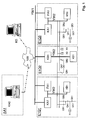
- FIG. 1 shows a schematic representation of a Switchgear or substation of an electrical Energy distribution network and an assigned control system.
- the Illustration shows three fields E1Q1, E1Q2 and E1Q3 one Switchgear and an operating station AA1 with one Data processing device KA0 with usual input and Output means for operation by a user.
- the Operating station AA1 is located in the substation itself or removed in a control center of a network operator arranged and over a communication network NW with a higher-level bus YW1 connected to the substation. On remote configuration server is also via the Communication network NW and the higher-level bus YW1 with Control units of the system connected for communication.
- the individual fields E1Q1, E1Q2 and E1Q3 each point Control devices on which control devices KA1, protection devices FA1 or input / output devices KB1. Control the control units, regulate, monitor and protect assigned primary devices of the Plant that fulfill the actual plant purpose. Primary devices include circuit breakers, disconnectors, Overhead lines, transformers, generators or motors.
- Control system functions for control are on the control units and monitoring of the primary devices installed.
- the control units are by means of communication, in the example by the superordinate bus YW1 and through process buses YW2 with each other connected.
- the control system functions are primary devices such as for example switches QA1, disconnectors QB1, QB2 and Voltage transmitters or voltage measuring devices X1, X2, X3 assigned.
- the primary devices are leading through electrical connections connected to each other, e.g. via busbars, field nodes and cable outlets. This Connections are as the topology of the primary devices writable.
- the designations KA1, FA1, KB1, YW1, etc. designate real ones Devices and control system functions of a system. To a to clearly identify a specific device, the device Name of the field preceded. So called for example E1Q1QA1 a switch QA1 of the field E1Q1.
- Current configuration information is therefore according to the invention determined and the configuration server KS transmitted.
- the current configuration information Description of the primary devices that are to be configured Is of concern, and its topology. This Description relates, for example, to a primary device Panel to which the control unit is assigned, or Primary devices on a specific busbar, or Primary devices of the entire substation. The description includes, depending on the type of primary device, for example permissible maximum values for voltage, current and power, Switching times, information about measuring circuits, i.e. Type and Parameters of transducers and sensors, type one Circuit breaker or disconnector, configuration of the earthing, Circuit diagram, properties of gas density sensors, Proximity switches, etc.
- the new Configuration information corresponds to new program units for the operation of the control unit. These program units are consistent with the current configuration information, that means that they are loadable and correct in the control unit are executable.
- the program units are programs for Microprocessors and / or programs for programmable logical components such as FPGAs (Field Programmable Gate Arrays).
- the program units are about Communication network NW and the higher-level bus YW1 the Control unit transmitted and in this in one Program memory or FPGA loaded.
- SCL dem Control unit in addition or alternatively an updated description of Device functions and device interfaces in SCL dem Control unit communicates and for its configuration used.
Landscapes
- Engineering & Computer Science (AREA)
- Power Engineering (AREA)
- Computer Networks & Wireless Communication (AREA)
- Signal Processing (AREA)
- Remote Monitoring And Control Of Power-Distribution Networks (AREA)
- Computer And Data Communications (AREA)
- Selective Calling Equipment (AREA)
- Logic Circuits (AREA)
- Mobile Radio Communication Systems (AREA)
- Small-Scale Networks (AREA)
- Radio Relay Systems (AREA)
- Data Exchanges In Wide-Area Networks (AREA)
- Stored Programmes (AREA)
Priority Applications (6)
| Application Number | Priority Date | Filing Date | Title |
|---|---|---|---|
| EP02405983A EP1420522B1 (fr) | 2002-11-15 | 2002-11-15 | Système de configuration de dispositifs de réseau et procédé de reconfiguration de dispositifs |
| DE50212642T DE50212642D1 (de) | 2002-11-15 | 2002-11-15 | Konfigurationssystem für Netzwerkgeräte und Verfahren zum Rekonfigurieren von Geräten |
| AT02405983T ATE405035T1 (de) | 2002-11-15 | 2002-11-15 | Konfigurationssystem für netzwerkgeräte und verfahren zum rekonfigurieren von geräten |
| US10/702,734 US20040098172A1 (en) | 2002-11-15 | 2003-11-07 | Configuration system for network appliances, and a method for reconfiguration of appliances |
| NO20035041A NO327130B1 (no) | 2002-11-15 | 2003-11-13 | Konfigurasjonssystem for nettverkapparater og fremgangsmate for rekonfigurering av apparater |
| CNB2003101165713A CN100350404C (zh) | 2002-11-15 | 2003-11-14 | 网络设备的配置系统及设备重新配置的方法 |
Applications Claiming Priority (1)
| Application Number | Priority Date | Filing Date | Title |
|---|---|---|---|
| EP02405983A EP1420522B1 (fr) | 2002-11-15 | 2002-11-15 | Système de configuration de dispositifs de réseau et procédé de reconfiguration de dispositifs |
Publications (2)
| Publication Number | Publication Date |
|---|---|
| EP1420522A1 true EP1420522A1 (fr) | 2004-05-19 |
| EP1420522B1 EP1420522B1 (fr) | 2008-08-13 |
Family
ID=29762760
Family Applications (1)
| Application Number | Title | Priority Date | Filing Date |
|---|---|---|---|
| EP02405983A Revoked EP1420522B1 (fr) | 2002-11-15 | 2002-11-15 | Système de configuration de dispositifs de réseau et procédé de reconfiguration de dispositifs |
Country Status (6)
| Country | Link |
|---|---|
| US (1) | US20040098172A1 (fr) |
| EP (1) | EP1420522B1 (fr) |
| CN (1) | CN100350404C (fr) |
| AT (1) | ATE405035T1 (fr) |
| DE (1) | DE50212642D1 (fr) |
| NO (1) | NO327130B1 (fr) |
Families Citing this family (7)
| Publication number | Priority date | Publication date | Assignee | Title |
|---|---|---|---|---|
| DE10244845A1 (de) * | 2002-09-20 | 2004-04-08 | Siemens Ag | Anordnung zum Steuern und Überwachen einer Schaltanlage |
| JP5052742B2 (ja) * | 2004-07-22 | 2012-10-17 | パナソニック株式会社 | 送信装置及びそれを用いた通信システム |
| US7529543B2 (en) | 2005-01-31 | 2009-05-05 | Fujitsu Limited | Configuring a device using a configuration manager |
| ATE534211T1 (de) * | 2008-06-26 | 2011-12-15 | Abb Research Ltd | Konfigurierung eines intelligenten elektronischen geräts |
| CN101384086B (zh) * | 2008-10-30 | 2012-07-04 | 华为技术有限公司 | 网络设备的配置方法、装置和系统 |
| CN101414175B (zh) * | 2008-11-21 | 2012-09-05 | 浙江中控技术股份有限公司 | 设备互联的方法、装置及系统 |
| WO2013182244A1 (fr) * | 2012-06-07 | 2013-12-12 | Abb Technology Ag | Module de configuration pour configurer automatiquement les capacités de communication d'un dispositif électronique intelligent |
Citations (3)
| Publication number | Priority date | Publication date | Assignee | Title |
|---|---|---|---|---|
| EP0911777A1 (fr) * | 1997-10-20 | 1999-04-28 | Schneider Electric Sa | Procédé de commande pour une installation électrique comportant des modules communiquants, dispositif et installation mettant en oeuvre un tel procédé |
| DE19850050C1 (de) * | 1998-10-30 | 2000-03-30 | Abb Research Ltd | Adaptives Verfahren zur Datenübertragung |
| WO2002071644A1 (fr) * | 2001-03-07 | 2002-09-12 | Planet System Co., Ltd. | Dispositif de communication sur le reseau electrique |
Family Cites Families (51)
| Publication number | Priority date | Publication date | Assignee | Title |
|---|---|---|---|---|
| US4204194A (en) * | 1977-05-23 | 1980-05-20 | General Electric Company | Meter terminal unit for use in automatic remote meter reading and control system |
| US4206443A (en) * | 1978-02-17 | 1980-06-03 | Westinghouse Electric Corp. | Protective load disconnect unit for remote load control systems |
| US4247786A (en) * | 1979-03-15 | 1981-01-27 | Cyborex Laboratories, Inc. | Energy management method using utility-generated signals |
| US4899129A (en) * | 1987-12-01 | 1990-02-06 | Smart House Limited Partnership | Automated appliance and energy distribution control system |
| EP0513206B1 (fr) * | 1990-01-30 | 1995-04-12 | Johnson Service Company | Systeme de gestion d'unites interconnectees en reseau |
| US5218552A (en) * | 1990-07-30 | 1993-06-08 | Smart House, L.P. | Control apparatus for use in a dwelling |
| US5365154A (en) * | 1991-07-12 | 1994-11-15 | North Coast Electronics, Inc. | Appliance control system and method |
| US5761083A (en) * | 1992-03-25 | 1998-06-02 | Brown, Jr.; Robert J. | Energy management and home automation system |
| US5621662A (en) * | 1994-02-15 | 1997-04-15 | Intellinet, Inc. | Home automation system |
| US5903213A (en) * | 1994-07-28 | 1999-05-11 | Southpower Limited | Device for energy load control |
| JP2991303B2 (ja) * | 1995-01-19 | 1999-12-20 | インターナシヨナル・ビジネス・マシーンズ・コーポレーシヨン | 制御ネットワークおよびその構成方法 |
| US5680324A (en) * | 1995-04-07 | 1997-10-21 | Schweitzer Engineering Laboratories, Inc. | Communications processor for electric power substations |
| US7099934B1 (en) * | 1996-07-23 | 2006-08-29 | Ewing Carrel W | Network-connecting power manager for remote appliances |
| US7043543B2 (en) * | 1996-07-23 | 2006-05-09 | Server Technology, Inc. | Vertical-mount electrical power distribution plugstrip |
| US5880677A (en) * | 1996-10-15 | 1999-03-09 | Lestician; Guy J. | System for monitoring and controlling electrical consumption, including transceiver communicator control apparatus and alternating current control apparatus |
| AU9557198A (en) * | 1997-10-13 | 1999-05-03 | Viserge Limited | A remote terminal unit assembly |
| US7162510B2 (en) * | 1998-03-16 | 2007-01-09 | Schneider Automation Inc. | Communication system for a control system over Ethernet and IP networks |
| IL139410A0 (en) * | 1998-05-07 | 2001-11-25 | Samsung Electronics Co Ltd | Method and apparatus for universally accessible command and control information in a network |
| US6161134A (en) * | 1998-10-30 | 2000-12-12 | 3Com Corporation | Method, apparatus and communications system for companion information and network appliances |
| US7376728B1 (en) * | 2000-07-25 | 2008-05-20 | Ricoh Company, Ltd. | Method and system for monitoring, collecting information, diagnosing and servicing a remote system |
| US7272815B1 (en) * | 1999-05-17 | 2007-09-18 | Invensys Systems, Inc. | Methods and apparatus for control configuration with versioning, security, composite blocks, edit selection, object swapping, formulaic values and other aspects |
| US6529589B1 (en) * | 1999-05-20 | 2003-03-04 | 3Com Corporation | Method and system for monitoring and controlling automation equipment by modem |
| JP2001016233A (ja) * | 1999-06-28 | 2001-01-19 | Oki Electric Ind Co Ltd | データ通信方法 |
| EP1115263A1 (fr) * | 1999-07-13 | 2001-07-11 | Matsushita Electric Industrial Co., Ltd. | Systeme de reseau de commande d'appareil electromenager |
| EP1131736B1 (fr) * | 1999-09-16 | 2006-03-29 | General Electric Company | Un dispositif de relais modulaire virtuel |
| US6735630B1 (en) * | 1999-10-06 | 2004-05-11 | Sensoria Corporation | Method for collecting data using compact internetworked wireless integrated network sensors (WINS) |
| EP1096348B1 (fr) * | 1999-11-01 | 2005-01-12 | Abb Research Ltd. | Intégration d'un appareil de commande sur site dans un système de commande d'une installation |
| US7379981B2 (en) * | 2000-01-31 | 2008-05-27 | Kenneth W. Garrard | Wireless communication enabled meter and network |
| JP3578959B2 (ja) * | 2000-02-24 | 2004-10-20 | 松下電器産業株式会社 | テーブルタップおよびテーブルタップを用いた監視システム |
| US6567001B1 (en) * | 2000-02-24 | 2003-05-20 | Simplex Time Recorder Co. | Fire control panel monitoring for degradation of wiring integrity during alarm state |
| CA2391405C (fr) * | 2000-04-10 | 2006-01-10 | Zensys A/S | Systeme domotique rf comprenant des controleurs susceptibles d'etre dupliques |
| DE10019322C2 (de) * | 2000-04-19 | 2003-06-18 | Rundfunkschutzrechte Ev | Vorrichtung zur Konditionierung der elektrischen Gebäudeinstallation für die schnelle Datenübertragung |
| US7085938B1 (en) * | 2000-06-27 | 2006-08-01 | General Electric Company | Protective relay with embedded web server |
| JP2002044765A (ja) * | 2000-07-28 | 2002-02-08 | Matsushita Electric Ind Co Ltd | 遠隔制御システムとゲートウェイ装置 |
| US6868292B2 (en) * | 2000-09-14 | 2005-03-15 | The Directv Group, Inc. | Device control via digitally stored program content |
| EP1233318A1 (fr) * | 2001-02-16 | 2002-08-21 | Abb Research Ltd. | Composants de software d'un système de commande décentralisé |
| US7085824B2 (en) * | 2001-02-23 | 2006-08-01 | Power Measurement Ltd. | Systems for in the field configuration of intelligent electronic devices |
| US6829704B2 (en) * | 2001-04-13 | 2004-12-07 | General Electric Company | Method and system to automatically activate software options upon initialization of a device |
| US6928471B2 (en) * | 2001-05-07 | 2005-08-09 | Quest Software, Inc. | Method and apparatus for measurement, analysis, and optimization of content delivery |
| US7194528B1 (en) * | 2001-05-18 | 2007-03-20 | Current Grid, Llc | Method and apparatus for processing inbound data within a powerline based communication system |
| US6754854B2 (en) * | 2001-06-04 | 2004-06-22 | Motorola, Inc. | System and method for event monitoring and error detection |
| US20030005090A1 (en) * | 2001-06-30 | 2003-01-02 | Sullivan Robert R. | System and method for integrating network services |
| US6894609B2 (en) * | 2001-07-17 | 2005-05-17 | Royal Thoughts, Llc | Electrical power control and sensor module for a wireless system |
| US20030069953A1 (en) * | 2001-09-28 | 2003-04-10 | Bottom David A. | Modular server architecture with high-availability management capability |
| DE10151115A1 (de) * | 2001-10-15 | 2003-05-08 | Siemens Ag | Verfahren zum Bedienen und zum Beobachten von Feldgeräten |
| US6954930B2 (en) * | 2002-02-19 | 2005-10-11 | International Business Machines Corporation | Remote validation of installation input data |
| KR100437042B1 (ko) * | 2002-03-20 | 2004-06-23 | 엘지전자 주식회사 | 가전기기 네트워크 시스템 및 그 제어방법 |
| US7421474B2 (en) * | 2002-05-13 | 2008-09-02 | Ricoh Co. Ltd. | Verification scheme for email message containing information about remotely monitored devices |
| US6865427B2 (en) * | 2002-07-18 | 2005-03-08 | International Business Machines Corporation | Method for management of workflows between devices in a pervasive embedded or external environment |
| US20040030766A1 (en) * | 2002-08-12 | 2004-02-12 | Michael Witkowski | Method and apparatus for switch fabric configuration |
| US20040088398A1 (en) * | 2002-11-06 | 2004-05-06 | Barlow Douglas B. | Systems and methods for providing autoconfiguration and management of nodes |
-
2002
- 2002-11-15 DE DE50212642T patent/DE50212642D1/de not_active Expired - Lifetime
- 2002-11-15 AT AT02405983T patent/ATE405035T1/de not_active IP Right Cessation
- 2002-11-15 EP EP02405983A patent/EP1420522B1/fr not_active Revoked
-
2003
- 2003-11-07 US US10/702,734 patent/US20040098172A1/en not_active Abandoned
- 2003-11-13 NO NO20035041A patent/NO327130B1/no not_active IP Right Cessation
- 2003-11-14 CN CNB2003101165713A patent/CN100350404C/zh not_active Expired - Fee Related
Patent Citations (3)
| Publication number | Priority date | Publication date | Assignee | Title |
|---|---|---|---|---|
| EP0911777A1 (fr) * | 1997-10-20 | 1999-04-28 | Schneider Electric Sa | Procédé de commande pour une installation électrique comportant des modules communiquants, dispositif et installation mettant en oeuvre un tel procédé |
| DE19850050C1 (de) * | 1998-10-30 | 2000-03-30 | Abb Research Ltd | Adaptives Verfahren zur Datenübertragung |
| WO2002071644A1 (fr) * | 2001-03-07 | 2002-09-12 | Planet System Co., Ltd. | Dispositif de communication sur le reseau electrique |
Also Published As
| Publication number | Publication date |
|---|---|
| CN100350404C (zh) | 2007-11-21 |
| US20040098172A1 (en) | 2004-05-20 |
| DE50212642D1 (de) | 2008-09-25 |
| NO20035041L (no) | 2004-05-18 |
| NO327130B1 (no) | 2009-04-27 |
| CN1501279A (zh) | 2004-06-02 |
| NO20035041D0 (no) | 2003-11-13 |
| ATE405035T1 (de) | 2008-08-15 |
| EP1420522B1 (fr) | 2008-08-13 |
Similar Documents
| Publication | Publication Date | Title |
|---|---|---|
| EP1096348B1 (fr) | Intégration d'un appareil de commande sur site dans un système de commande d'une installation | |
| EP0906596B1 (fr) | Systeme d'automatisation de processus industriels | |
| EP2988183B1 (fr) | Système d'observation et/ou de commande d'une installation | |
| EP1191662B1 (fr) | Configuration d'un système de contrôle d'une installation électrique | |
| EP3086428B1 (fr) | Procédé et système de paramétrage d'appareils de commande sur site et/ou d'appareils de protection d'un système de commutation | |
| EP2697888B1 (fr) | Méthode de détermination de la topologie d'un réseau de distribution basse tension | |
| DE69715868T2 (de) | Abklemmbares elektrisches gerät mit einer ortsfesten einheit und einer entfernbaren und abklemmbaren einheit welche in der ortsfesten einheit installiert ist | |
| EP0224711A1 (fr) | Procédure d'actionnement protégé contre des erreurs de commutation des commutateurs d'une installation de commutation | |
| EP2684335B1 (fr) | Installation d'automatisation d'énergie et procédé servant à faire fonctionner une installation d'automatisation d'énergie | |
| EP2598954B1 (fr) | Configuration des liaisons de communication des appareils de terrain d'un équipement d'automatisation de la distribution d'énergie | |
| WO2009049656A1 (fr) | Procédé de configuration d'un ensemble destiné à protéger, à commander ou à surveiller une installation d'alimentation en énergie électrique ou de commutation électrique | |
| WO1998054810A1 (fr) | Controle telecommande d'un discontacteur electronique | |
| EP1420522B1 (fr) | Système de configuration de dispositifs de réseau et procédé de reconfiguration de dispositifs | |
| DE102011001668A1 (de) | Administrierbares Energienetz mit Datenübertragungsfunktion | |
| EP2274874B1 (fr) | Contrôle de la liaison de communication entre des appareils de terrain | |
| EP1805567B1 (fr) | Procede et systeme d'automatisation pour commander et/ou surveiller au moins un appareil de terrain | |
| EP1690390B1 (fr) | Procede de transmission de donnees via un bus de donnees, et systeme et passerelle permettant la mise en oeuvre dudit procede | |
| EP2359571B1 (fr) | Dispositif présentant un appareil de centre de commande et une station d'installations en liaison avec celui-ci, et procédé permettant son fonctionnement | |
| DE102018116891A1 (de) | Klemmenmodul, ein Kopfmodul und ein System zur Erhebung von Daten aus einer Anlage der Automatisierungstechnik | |
| DE102011082504A1 (de) | Verfahren und Vorrichtung zum Stabilisieren eines Energieversorgungsnetzwerks | |
| DE10029448A1 (de) | Prozeßleittechniksystem | |
| EP1420496B1 (fr) | Dispositif de protection et procédé pour installer une fonction de protection dans un tel dispositif | |
| EP3930130B1 (fr) | Procédé de paramétrage d'un agencement de protection, agencement de protection et produit de programme informatique | |
| EP2193590B1 (fr) | Appareil permettant de protéger, de commander ou de surveiller une installation de commutation électrique ou d'alimentation électrique et procédé permettant de le faire fonctionner | |
| EP1046972B1 (fr) | Representation d' appareils à l'aide d'un logiciel |
Legal Events
| Date | Code | Title | Description |
|---|---|---|---|
| PUAI | Public reference made under article 153(3) epc to a published international application that has entered the european phase |
Free format text: ORIGINAL CODE: 0009012 |
|
| AK | Designated contracting states |
Kind code of ref document: A1 Designated state(s): AT BE BG CH CY CZ DE DK EE ES FI FR GB GR IE IT LI LU MC NL PT SE SK TR |
|
| AX | Request for extension of the european patent |
Extension state: AL LT LV MK RO SI |
|
| 17P | Request for examination filed |
Effective date: 20041022 |
|
| AKX | Designation fees paid |
Designated state(s): AT BE BG CH CY CZ DE DK EE ES FI FR GB GR IE IT LI LU MC NL PT SE SK TR |
|
| 17Q | First examination report despatched |
Effective date: 20050404 |
|
| GRAP | Despatch of communication of intention to grant a patent |
Free format text: ORIGINAL CODE: EPIDOSNIGR1 |
|
| GRAS | Grant fee paid |
Free format text: ORIGINAL CODE: EPIDOSNIGR3 |
|
| GRAA | (expected) grant |
Free format text: ORIGINAL CODE: 0009210 |
|
| AK | Designated contracting states |
Kind code of ref document: B1 Designated state(s): AT BE BG CH CY CZ DE DK EE ES FI FR GB GR IE IT LI LU MC NL PT SE SK TR |
|
| REG | Reference to a national code |
Ref country code: GB Ref legal event code: FG4D Free format text: NOT ENGLISH |
|
| REG | Reference to a national code |
Ref country code: CH Ref legal event code: EP |
|
| REG | Reference to a national code |
Ref country code: IE Ref legal event code: FG4D Free format text: LANGUAGE OF EP DOCUMENT: GERMAN |
|
| REF | Corresponds to: |
Ref document number: 50212642 Country of ref document: DE Date of ref document: 20080925 Kind code of ref document: P |
|
| PG25 | Lapsed in a contracting state [announced via postgrant information from national office to epo] |
Ref country code: NL Free format text: LAPSE BECAUSE OF FAILURE TO SUBMIT A TRANSLATION OF THE DESCRIPTION OR TO PAY THE FEE WITHIN THE PRESCRIBED TIME-LIMIT Effective date: 20080813 Ref country code: ES Free format text: LAPSE BECAUSE OF FAILURE TO SUBMIT A TRANSLATION OF THE DESCRIPTION OR TO PAY THE FEE WITHIN THE PRESCRIBED TIME-LIMIT Effective date: 20081124 |
|
| PG25 | Lapsed in a contracting state [announced via postgrant information from national office to epo] |
Ref country code: FI Free format text: LAPSE BECAUSE OF FAILURE TO SUBMIT A TRANSLATION OF THE DESCRIPTION OR TO PAY THE FEE WITHIN THE PRESCRIBED TIME-LIMIT Effective date: 20080813 |
|
| REG | Reference to a national code |
Ref country code: IE Ref legal event code: FD4D |
|
| PG25 | Lapsed in a contracting state [announced via postgrant information from national office to epo] |
Ref country code: BG Free format text: LAPSE BECAUSE OF FAILURE TO SUBMIT A TRANSLATION OF THE DESCRIPTION OR TO PAY THE FEE WITHIN THE PRESCRIBED TIME-LIMIT Effective date: 20081113 Ref country code: IE Free format text: LAPSE BECAUSE OF FAILURE TO SUBMIT A TRANSLATION OF THE DESCRIPTION OR TO PAY THE FEE WITHIN THE PRESCRIBED TIME-LIMIT Effective date: 20080813 Ref country code: DK Free format text: LAPSE BECAUSE OF FAILURE TO SUBMIT A TRANSLATION OF THE DESCRIPTION OR TO PAY THE FEE WITHIN THE PRESCRIBED TIME-LIMIT Effective date: 20080813 |
|
| PLBI | Opposition filed |
Free format text: ORIGINAL CODE: 0009260 |
|
| PG25 | Lapsed in a contracting state [announced via postgrant information from national office to epo] |
Ref country code: PT Free format text: LAPSE BECAUSE OF FAILURE TO SUBMIT A TRANSLATION OF THE DESCRIPTION OR TO PAY THE FEE WITHIN THE PRESCRIBED TIME-LIMIT Effective date: 20090113 Ref country code: SK Free format text: LAPSE BECAUSE OF FAILURE TO SUBMIT A TRANSLATION OF THE DESCRIPTION OR TO PAY THE FEE WITHIN THE PRESCRIBED TIME-LIMIT Effective date: 20080813 Ref country code: CZ Free format text: LAPSE BECAUSE OF FAILURE TO SUBMIT A TRANSLATION OF THE DESCRIPTION OR TO PAY THE FEE WITHIN THE PRESCRIBED TIME-LIMIT Effective date: 20080813 |
|
| BERE | Be: lapsed |
Owner name: ABB RESEARCH LTD. Effective date: 20081130 |
|
| 26 | Opposition filed |
Opponent name: SIEMENS AKTIENGESELLSCHAFT Effective date: 20090504 |
|
| PLAX | Notice of opposition and request to file observation + time limit sent |
Free format text: ORIGINAL CODE: EPIDOSNOBS2 |
|
| PG25 | Lapsed in a contracting state [announced via postgrant information from national office to epo] |
Ref country code: MC Free format text: LAPSE BECAUSE OF NON-PAYMENT OF DUE FEES Effective date: 20081130 |
|
| REG | Reference to a national code |
Ref country code: CH Ref legal event code: PL |
|
| PG25 | Lapsed in a contracting state [announced via postgrant information from national office to epo] |
Ref country code: EE Free format text: LAPSE BECAUSE OF FAILURE TO SUBMIT A TRANSLATION OF THE DESCRIPTION OR TO PAY THE FEE WITHIN THE PRESCRIBED TIME-LIMIT Effective date: 20080813 |
|
| PG25 | Lapsed in a contracting state [announced via postgrant information from national office to epo] |
Ref country code: BE Free format text: LAPSE BECAUSE OF NON-PAYMENT OF DUE FEES Effective date: 20081130 |
|
| PG25 | Lapsed in a contracting state [announced via postgrant information from national office to epo] |
Ref country code: LI Free format text: LAPSE BECAUSE OF NON-PAYMENT OF DUE FEES Effective date: 20081130 Ref country code: CH Free format text: LAPSE BECAUSE OF NON-PAYMENT OF DUE FEES Effective date: 20081130 |
|
| PLBB | Reply of patent proprietor to notice(s) of opposition received |
Free format text: ORIGINAL CODE: EPIDOSNOBS3 |
|
| PG25 | Lapsed in a contracting state [announced via postgrant information from national office to epo] |
Ref country code: SE Free format text: LAPSE BECAUSE OF FAILURE TO SUBMIT A TRANSLATION OF THE DESCRIPTION OR TO PAY THE FEE WITHIN THE PRESCRIBED TIME-LIMIT Effective date: 20081113 Ref country code: AT Free format text: LAPSE BECAUSE OF NON-PAYMENT OF DUE FEES Effective date: 20081115 |
|
| PG25 | Lapsed in a contracting state [announced via postgrant information from national office to epo] |
Ref country code: LU Free format text: LAPSE BECAUSE OF NON-PAYMENT OF DUE FEES Effective date: 20081115 Ref country code: CY Free format text: LAPSE BECAUSE OF FAILURE TO SUBMIT A TRANSLATION OF THE DESCRIPTION OR TO PAY THE FEE WITHIN THE PRESCRIBED TIME-LIMIT Effective date: 20080813 |
|
| PG25 | Lapsed in a contracting state [announced via postgrant information from national office to epo] |
Ref country code: TR Free format text: LAPSE BECAUSE OF FAILURE TO SUBMIT A TRANSLATION OF THE DESCRIPTION OR TO PAY THE FEE WITHIN THE PRESCRIBED TIME-LIMIT Effective date: 20080813 |
|
| PG25 | Lapsed in a contracting state [announced via postgrant information from national office to epo] |
Ref country code: GR Free format text: LAPSE BECAUSE OF FAILURE TO SUBMIT A TRANSLATION OF THE DESCRIPTION OR TO PAY THE FEE WITHIN THE PRESCRIBED TIME-LIMIT Effective date: 20081114 |
|
| RDAF | Communication despatched that patent is revoked |
Free format text: ORIGINAL CODE: EPIDOSNREV1 |
|
| REG | Reference to a national code |
Ref country code: DE Ref legal event code: R064 Ref document number: 50212642 Country of ref document: DE Ref country code: DE Ref legal event code: R103 Ref document number: 50212642 Country of ref document: DE |
|
| PGFP | Annual fee paid to national office [announced via postgrant information from national office to epo] |
Ref country code: FR Payment date: 20121130 Year of fee payment: 11 Ref country code: DE Payment date: 20121121 Year of fee payment: 11 |
|
| PGFP | Annual fee paid to national office [announced via postgrant information from national office to epo] |
Ref country code: IT Payment date: 20121127 Year of fee payment: 11 Ref country code: GB Payment date: 20121120 Year of fee payment: 11 |
|
| RDAG | Patent revoked |
Free format text: ORIGINAL CODE: 0009271 |
|
| STAA | Information on the status of an ep patent application or granted ep patent |
Free format text: STATUS: PATENT REVOKED |
|
| 27W | Patent revoked |
Effective date: 20121221 |
|
| GBPR | Gb: patent revoked under art. 102 of the ep convention designating the uk as contracting state |
Effective date: 20121221 |
|
| REG | Reference to a national code |
Ref country code: AT Ref legal event code: MA03 Ref document number: 405035 Country of ref document: AT Kind code of ref document: T Effective date: 20121221 |
|
| REG | Reference to a national code |
Ref country code: DE Ref legal event code: R107 Ref document number: 50212642 Country of ref document: DE Effective date: 20130926 |