EP1420868B1 - Injecteur de fluide comportant des orifices d'event/dosage - Google Patents
Injecteur de fluide comportant des orifices d'event/dosage Download PDFInfo
- Publication number
- EP1420868B1 EP1420868B1 EP02744388A EP02744388A EP1420868B1 EP 1420868 B1 EP1420868 B1 EP 1420868B1 EP 02744388 A EP02744388 A EP 02744388A EP 02744388 A EP02744388 A EP 02744388A EP 1420868 B1 EP1420868 B1 EP 1420868B1
- Authority
- EP
- European Patent Office
- Prior art keywords
- storage tank
- fluid
- flow
- flow line
- connection
- Prior art date
- Legal status (The legal status is an assumption and is not a legal conclusion. Google has not performed a legal analysis and makes no representation as to the accuracy of the status listed.)
- Expired - Lifetime
Links
Images



Classifications
-
- B—PERFORMING OPERATIONS; TRANSPORTING
- B05—SPRAYING OR ATOMISING IN GENERAL; APPLYING FLUENT MATERIALS TO SURFACES, IN GENERAL
- B05B—SPRAYING APPARATUS; ATOMISING APPARATUS; NOZZLES
- B05B7/00—Spraying apparatus for discharge of liquids or other fluent materials from two or more sources, e.g. of liquid and air, of powder and gas
- B05B7/24—Spraying apparatus for discharge of liquids or other fluent materials from two or more sources, e.g. of liquid and air, of powder and gas with means, e.g. a container, for supplying liquid or other fluent material to a discharge device
- B05B7/2402—Apparatus to be carried on or by a person, e.g. by hand; Apparatus comprising containers fixed to the discharge device
- B05B7/244—Apparatus to be carried on or by a person, e.g. by hand; Apparatus comprising containers fixed to the discharge device using carrying liquid for feeding, e.g. by suction, pressure or dissolution, a carried liquid from the container to the nozzle
- B05B7/2443—Apparatus to be carried on or by a person, e.g. by hand; Apparatus comprising containers fixed to the discharge device using carrying liquid for feeding, e.g. by suction, pressure or dissolution, a carried liquid from the container to the nozzle the carried liquid and the main stream of carrying liquid being brought together downstream of the container before discharge
- B05B7/2445—Apparatus to be carried on or by a person, e.g. by hand; Apparatus comprising containers fixed to the discharge device using carrying liquid for feeding, e.g. by suction, pressure or dissolution, a carried liquid from the container to the nozzle the carried liquid and the main stream of carrying liquid being brought together downstream of the container before discharge and a secondary stream of carrying liquid being brought together in the container or putting the carried liquid under pressure in the container
-
- B—PERFORMING OPERATIONS; TRANSPORTING
- B01—PHYSICAL OR CHEMICAL PROCESSES OR APPARATUS IN GENERAL
- B01F—MIXING, e.g. DISSOLVING, EMULSIFYING OR DISPERSING
- B01F25/00—Flow mixers; Mixers for falling materials, e.g. solid particles
- B01F25/30—Injector mixers
- B01F25/31—Injector mixers in conduits or tubes through which the main component flows
- B01F25/315—Injector mixers in conduits or tubes through which the main component flows wherein a difference of pressure at different points of the conduit causes introduction of the additional component into the main component
-
- B—PERFORMING OPERATIONS; TRANSPORTING
- B01—PHYSICAL OR CHEMICAL PROCESSES OR APPARATUS IN GENERAL
- B01F—MIXING, e.g. DISSOLVING, EMULSIFYING OR DISPERSING
- B01F25/00—Flow mixers; Mixers for falling materials, e.g. solid particles
- B01F25/30—Injector mixers
- B01F25/31—Injector mixers in conduits or tubes through which the main component flows
- B01F25/316—Injector mixers in conduits or tubes through which the main component flows with containers for additional components fixed to the conduit
-
- F—MECHANICAL ENGINEERING; LIGHTING; HEATING; WEAPONS; BLASTING
- F04—POSITIVE - DISPLACEMENT MACHINES FOR LIQUIDS; PUMPS FOR LIQUIDS OR ELASTIC FLUIDS
- F04F—PUMPING OF FLUID BY DIRECT CONTACT OF ANOTHER FLUID OR BY USING INERTIA OF FLUID TO BE PUMPED; SIPHONS
- F04F1/00—Pumps using positively or negatively pressurised fluid medium acting directly on the liquid to be pumped
- F04F1/06—Pumps using positively or negatively pressurised fluid medium acting directly on the liquid to be pumped the fluid medium acting on the surface of the liquid to be pumped
-
- F—MECHANICAL ENGINEERING; LIGHTING; HEATING; WEAPONS; BLASTING
- F04—POSITIVE - DISPLACEMENT MACHINES FOR LIQUIDS; PUMPS FOR LIQUIDS OR ELASTIC FLUIDS
- F04F—PUMPING OF FLUID BY DIRECT CONTACT OF ANOTHER FLUID OR BY USING INERTIA OF FLUID TO BE PUMPED; SIPHONS
- F04F5/00—Jet pumps, i.e. devices in which flow is induced by pressure drop caused by velocity of another fluid flow
- F04F5/14—Jet pumps, i.e. devices in which flow is induced by pressure drop caused by velocity of another fluid flow the inducing fluid being elastic fluid
- F04F5/24—Jet pumps, i.e. devices in which flow is induced by pressure drop caused by velocity of another fluid flow the inducing fluid being elastic fluid displacing liquids, e.g. containing solids, or liquids and elastic fluids
-
- B—PERFORMING OPERATIONS; TRANSPORTING
- B01—PHYSICAL OR CHEMICAL PROCESSES OR APPARATUS IN GENERAL
- B01F—MIXING, e.g. DISSOLVING, EMULSIFYING OR DISPERSING
- B01F23/00—Mixing according to the phases to be mixed, e.g. dispersing or emulsifying
- B01F23/40—Mixing liquids with liquids; Emulsifying
-
- B—PERFORMING OPERATIONS; TRANSPORTING
- B01—PHYSICAL OR CHEMICAL PROCESSES OR APPARATUS IN GENERAL
- B01F—MIXING, e.g. DISSOLVING, EMULSIFYING OR DISPERSING
- B01F35/00—Accessories for mixers; Auxiliary operations or auxiliary devices; Parts or details of general application
- B01F35/80—Forming a predetermined ratio of the substances to be mixed
-
- Y—GENERAL TAGGING OF NEW TECHNOLOGICAL DEVELOPMENTS; GENERAL TAGGING OF CROSS-SECTIONAL TECHNOLOGIES SPANNING OVER SEVERAL SECTIONS OF THE IPC; TECHNICAL SUBJECTS COVERED BY FORMER USPC CROSS-REFERENCE ART COLLECTIONS [XRACs] AND DIGESTS
- Y02—TECHNOLOGIES OR APPLICATIONS FOR MITIGATION OR ADAPTATION AGAINST CLIMATE CHANGE
- Y02P—CLIMATE CHANGE MITIGATION TECHNOLOGIES IN THE PRODUCTION OR PROCESSING OF GOODS
- Y02P60/00—Technologies relating to agriculture, livestock or agroalimentary industries
- Y02P60/20—Reduction of greenhouse gas [GHG] emissions in agriculture, e.g. CO2
- Y02P60/21—Dinitrogen oxide [N2O], e.g. using aquaponics, hydroponics or efficiency measures
-
- Y—GENERAL TAGGING OF NEW TECHNOLOGICAL DEVELOPMENTS; GENERAL TAGGING OF CROSS-SECTIONAL TECHNOLOGIES SPANNING OVER SEVERAL SECTIONS OF THE IPC; TECHNICAL SUBJECTS COVERED BY FORMER USPC CROSS-REFERENCE ART COLLECTIONS [XRACs] AND DIGESTS
- Y10—TECHNICAL SUBJECTS COVERED BY FORMER USPC
- Y10T—TECHNICAL SUBJECTS COVERED BY FORMER US CLASSIFICATION
- Y10T137/00—Fluid handling
- Y10T137/0318—Processes
-
- Y—GENERAL TAGGING OF NEW TECHNOLOGICAL DEVELOPMENTS; GENERAL TAGGING OF CROSS-SECTIONAL TECHNOLOGIES SPANNING OVER SEVERAL SECTIONS OF THE IPC; TECHNICAL SUBJECTS COVERED BY FORMER USPC CROSS-REFERENCE ART COLLECTIONS [XRACs] AND DIGESTS
- Y10—TECHNICAL SUBJECTS COVERED BY FORMER USPC
- Y10T—TECHNICAL SUBJECTS COVERED BY FORMER US CLASSIFICATION
- Y10T137/00—Fluid handling
- Y10T137/2931—Diverse fluid containing pressure systems
- Y10T137/3112—Main line flow displaces additive from shunt reservoir
-
- Y—GENERAL TAGGING OF NEW TECHNOLOGICAL DEVELOPMENTS; GENERAL TAGGING OF CROSS-SECTIONAL TECHNOLOGIES SPANNING OVER SEVERAL SECTIONS OF THE IPC; TECHNICAL SUBJECTS COVERED BY FORMER USPC CROSS-REFERENCE ART COLLECTIONS [XRACs] AND DIGESTS
- Y10—TECHNICAL SUBJECTS COVERED BY FORMER USPC
- Y10T—TECHNICAL SUBJECTS COVERED BY FORMER US CLASSIFICATION
- Y10T137/00—Fluid handling
- Y10T137/4891—With holder for solid, flaky or pulverized material to be dissolved or entrained
-
- Y—GENERAL TAGGING OF NEW TECHNOLOGICAL DEVELOPMENTS; GENERAL TAGGING OF CROSS-SECTIONAL TECHNOLOGIES SPANNING OVER SEVERAL SECTIONS OF THE IPC; TECHNICAL SUBJECTS COVERED BY FORMER USPC CROSS-REFERENCE ART COLLECTIONS [XRACs] AND DIGESTS
- Y10—TECHNICAL SUBJECTS COVERED BY FORMER USPC
- Y10T—TECHNICAL SUBJECTS COVERED BY FORMER US CLASSIFICATION
- Y10T137/00—Fluid handling
- Y10T137/8593—Systems
- Y10T137/8597—Main line as motive fluid for follower-type feeder
Definitions
- This invention relates to storage tanks and fluid injection systems, specifically to injection metering devices.
- a variety of means have been used to inject fluids into fluid streams. These include metering pumps, water powered pumps, siphon devices, flow through devices and gravity feed drainage equipment.
- Metering pumps are either set to inject a predetermined amount into a fluid stream without a means of adjusting to changes in flow volume in the fluid stream, or they are controlled electronically by flow sensors located in the fluid stream.
- the components of this type of system are mechanical and electronic so they are subject to wear and mechanical failure.
- Water powered pumps adjust automatically to changes in flow in the fluid stream but are a mechanical device with a number of seal points. The seals require frequent maintenance for the unit to operate properly. This design is limited in the amount of fluid flow it can operate with and as flows increase, the cost of the device increases.
- Siphon devices rely on a high restriction in the fluid stream to create venturi suction strong enough to pull the injection solution from the storage container. They require high pressure to operate and the high restriction in the fluid stream greatly reduces the fluid stream volume. Fluctuations in pressure can cause the device to not inject continuously creating uneven distribution. They are also unable to dependably inject solutions such as water-soluble fertilizers without plugging. Venturi systems generally have relatively small flow orifices and the fertilizer solution has a tendency to settle, creating sedimentation that plugs these orifices. Flow through devices typically channel the flow of the fluid stream through a container that holds a soluble product that slowly breaks down, releasing the product into the stream. This method doesn't control the amount being distributed and can give unreliable distribution. It is common for the soluble products to melt as they sit in the water while the system is not operating and release a large amount when the system is restarted.
- the U.S. Patent number 3,809,291 Liquid Proportioning System by Chester A. Purdy is a gravity feed system that uses an internal mixing chamber to combine two liquids to be dispensed into a fluid stream. It requires an electrical controller, a pressure switch and a float valve to control fluid flow into the tank.
- the U. S. Patent number 5,544, 810 Precision-Ratioed Fluid-Mixing Device And System by Horvath, Abrams and Helf utilizes a high pressure flow line to create a venturi to draw multiple fluids from multiple unpressurized containers and accurately mix them into one solution.
- the system has an air vent to the atmosphere to prevent siphoning of fluid from the storage containers when the system is not operating.
- This design requires a high-pressure flow line to create enough vacuum to draw fluids from the containers. This creates a high restriction in the flow line, significantly reducing flow volume and pressure. It also requires multiple containers to store the various solutions, which requires piping connections between all the containers used. This design cannot operate at low pressures or automatically mix dry products and keep them an injectable solution.
- U.S. Patent 3,052,525 discloses an apparatus for introducing controlled quantities of liquids and solids into a fluid medium using an outer container and an inner bladder or bellows.
- US Patent 3,455,054 discloses a mixing system in which fluid is diverted from the main conduit to flow through a container in order to mix with and collect the substance to be mixed with the fluid.
- US Patent 2,857,202 discloses a dispenser for solids and liquids incorporating an agitator flexible hose which is moveable to agitate the contents of the dispensing container.
- My invention solves a number of problems that have been present in prior art. It eliminates the need for a mechanical check valve and air relief valves, which are subject to wear, leakage and failure. It operates at very low pressures without the need for restriction in the flow line. It operates totally on pressure from the flow line and injects very accurately. It can handle dry products as well as very heavy products without plugging or manual mixing. It can inject multiple solutions at independent injection rates from one storage tank.
- a fluid injector with vent/proportioner ports comprises a fluid injector that utilizes fluid from a flow line to accurately inject fluids into the flow line.
- the system mixes incoming fluid with outgoing injection solution to provide a wide range of flow adjustment. It uses flow orifices to provide air release from the storage tank as well as provide back flow protection. It utilizes multiple bladders to inject multiple solutions from one storage tank.
- FIG. 1 shows an overview of the system operating and how it is connected to a fluid flow line.
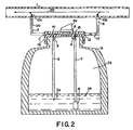
- FIG. 2 shows an overview of the system operating during back flow conditions.
- FIG. 3 shows an overview of the system operating during back flow with vacuum conditions.
- FIG. 4 shows an overview of the system with multiple bladders.
- FIG. 1 A preferred embodiment of the fluid injector with vent/proportioner ports is shown in FIG. 1.
- This side view shows a basic view of the invention and how it connects to a fluid flow line.
- the system can be manufactured from various types of plastic, metal or both. Plastic connections can be glued or threaded. Metal connections can be threaded, welded or braised.
- the tank inlet connection 11 is connected to fluid flow line 1 by attaching inlet connection tube 2 to tapping fitting 10a.
- the tank outlet connection 12 is connected to fluid flow line 1 by attaching outlet connection tube 9 to tapping fitting 10b
- the tank inlet connection 11 is connected to tank outlet connection 12 by crossover connection 8.
- Mixing valve 8a is located in the crossover connection 8, between tank inlet connection 11 and tank outlet connection 12.
- the tank inlet connection 11 is attached to tank inlet port 14, which is attached to inlet vent/proportioner port 3 and agitation tube 5.
- Agitation nozzle 5a is attached to the end of the agitation tube 5, which extends into the bottom portion of storage tank 13.
- the tank outlet connection 12 is attached to the tank outlet port 4, which is attached to outlet vent/proportioner port 4 and pickup tube 7.
- Pickup filter 6 is attached to the end of pickup tube 7, which extends to the bottom of storage tank 13.
- Site tube 17 is located in the outlet connection tube 9 between tank outlet connection 12 and tap fitting 10b.
- the method of using the fluid injector with vent/proportioner ports is to connect it to a fluid flow line as shown in FIG. 1.
- a positive pressure is created by tap fitting 10a creating fluid flow from fluid flow line 1, which is directed through the inlet connection tube 2 to tank inlet connection 11.
- the fluid is then directed through crossover connection 8 to the tank outlet connection 12 and through an inlet port 14 to storage tank 13.
- the amount of flow to each area is controlled by mixing valve 8a.
- mixing valve 8a As mixing valve 8a is opened, more fluid flows through crossover connection 8 and less fluid through tank inlet port 14. This reduces the amount of fluid leaving the storage tank 13 which reduces the concentration of the fluid injected into the fluid flow line 1.
- the fluid entering the storage tank 13 through tank inlet port 14 flows through inlet proportion/vent port 3 determines the amount of flow diverted to the top and bottom of the storage tank 13. This controls the amount of agitation action directed at injection solution 24.
- the balance of the fluid entering the storage tank 13 is directed through the agitation tube 5, through agitation nozzle 5a, into the bottom of the tank and into the injection solution in the bottom of the tank.
- dry soluble products are mixed automatically with inlet fluid from fluid flow line 1 as the storage tank 13 is filling.
- the air in storage tank 13 is exhausted through outlet vent/proportioner port 4 into the fluid flow line 1. Since air moves more easily than liquid, no fluid leaves the storage tank 13 until all the air has been exhausted. This provides thorough mixing of injection solution 24 which creates accurate injection and prevents plugging.
- Flow entering storage tank 13 pressurizes storage tank 13 to the same pressure as the fluid flow line 1.
- a negative pressure is created by tap fitting 10b creating flow from storage tank 13.
- This flow is directed through pickup filter 6 through pickup tube 7 as well as through vent/proportioner outlet port 4 to tank outlet port 15.
- the size of the vent/proportioner outlet port 4 determines the mix ratio of fluid inside the storage tank 13 and injection solution 20. It then flows through crossover connection 8, where it mixes with inlet flow and then flows through tank outlet connection 12 to tap fitting 10b through outlet connection tube 9.
- Tap fittings 10a and 10b do not create any restriction in flow line 1. Because the storage tank 13 is pressurized to the same pressure as flow line 1, any changes in flow line 1 pressure or velocity is communicated to storage tank 13 immediately, making the system very responsive to changes in flow and very accurate. This also enables the system to begin operating with as little as two gallons per hour flow in fluid flow line 1 and at as little as 5 PSI operating pressure. The system has no capacity or volume restrictions. If flow restriction is put between tap fitting 10a and tap fitting 10b, the operating range is increased. It can be adapted to any size application. Because the flow through the system is consistent, not pulsating, the injection solution 24 entering the fluid flow line 1 is consistent throughout the fluid flow line 1 solution.
- FIG. 2 shows the flow pattern when a back flow condition exists.
- pressure is lost in fluid flow line 1 so any fluid in the fluid flow line 1 reverses direction. This reverses the flow through the system by creating a positive pressure at tap fitting 10b.
- This directs flow into the storage tank through the fertilizer outlet tube 9, the tank outlet connection 12 and then through the tank outlet port 15 and crossover connection 8.
- the adjustment valve 8a setting determines the amount of fluid that reenters the storage tank. The more open the mixing valve 8a is set, the more fluid that will bypass the storage tank 13 and return to the fluid flow line 1 through the inlet connection tube 2. The fluid that does not go through the crossover connection 8 will flow into the storage tank 13 through the tank outlet port 15.
- FIG. 3 shows how the system operates when all the fluid has been eliminated from the fluid flow line 1.
- the fluid is replaced by air which creates a vacuum condition.
- the air follows the same flow path as the fluid does during back flow conditions. Once air has entered the storage tank 13 through tank outlet port 4, it flows through the inlet vent/proportioner port 3 to the fluid flow line 1. Because air flows more easily than fluid, only air flows through the system. This puts the system in an air lock condition which prohibits any liquid from leaving the storage tank 13.
- FIG. 4. An additional embodiment is shown in FIG. 4. It shows the addition of bladder 16a and 16b.
- Bladder 16a is connected to vent/proportioner port 4a that is connected to tank outlet port 4.
- Bladder 16b is connected to vent/proportioner port 4b that is connected to tank outlet port 4.
- Fill port 17a is connected to bladder 16a.
- Fill port 17b is connected to bladder 16b.
- Fill port 17c is connected to storage tank 13.
- Drain valve 18 is connected to storage tank 13.
- Fill port valve 19a is connected to fill port 17a.
- Fill port valve 19b is connected to fill port 17b.
- Fill port valve 19c is connected to fill port 17c.
- FIG. 4 Operations
- the method of using the fluid injector with vent/proportioner ports as shown in FIG. 4 is to turn off all flow in fluid flow line 1.
- Relieve system pressure by opening a valve downstream in the fluid flow line 1.
- close fill port valve 19b When the desired quantity of injection solution 22 has been poured in, close fill port valve 19b.
- bladder 16a and bladder 16b are made of flexible material that collapses as fluid is removed. They are used to contain injection solutions that need to be separated due to their reaction to other solutions in the storage tank 13 or if their specific gravity is the same or lighter than the fluid entering the storage tank 13 from the fluid flow line 1.
- injection solution 21 leaves bladder 16a and flows through tank outlet port 15, it is premised with fluid from storage tank 13 to a preset ratio determined by the orifice size of the outlet vent/proportioner port 4a.
- injection solution 22 leaves bladder 16b and flows through tank outlet port 15, it is premixed with fluid from storage tank 13 to a preset ratio determined by the orifice size of the outlet vent/proportioner port 4b. All solutions leaving storage tank 13 are then mixed with the fluid in crossover connection 8.
- Mixing valve 8a sets the injection ratio for the combined solutions before they enter fluid flow line 1.
- the fluid injector with vent/proportioner ports will provide many advantages to consumers, industry and the environment. It provides an economical means of accurately injecting solutions that are normally difficult to inject. It can inject multiple solutions simultaneously into a flow line, each with their own injection ratio. Incompatible products can be combined in one tank and one installation. It is very easy to use and has a long service life with very low maintenance requirements. It easily adapts from small to large applications. It can be manufactured easily and economically from products readily available in the marketplace. It can be fabricated from plastic or metal piping components or molded.
Landscapes
- Engineering & Computer Science (AREA)
- Chemical & Material Sciences (AREA)
- Chemical Kinetics & Catalysis (AREA)
- Mechanical Engineering (AREA)
- General Engineering & Computer Science (AREA)
- Fluid Mechanics (AREA)
- Physics & Mathematics (AREA)
- Accessories For Mixers (AREA)
- Loading And Unloading Of Fuel Tanks Or Ships (AREA)
- Devices For Dispensing Beverages (AREA)
- Coating Apparatus (AREA)
- Feeding, Discharge, Calcimining, Fusing, And Gas-Generation Devices (AREA)
- Gas Separation By Absorption (AREA)
- Respiratory Apparatuses And Protective Means (AREA)
Claims (17)
- Distributeur de solution destiné à délivrer, à un débit dosé, une solution contenue dans un récipient de stockage (13) en un flux de fluide dans une ligne de flux (1), le distributeur de solution comprenant :un raccord d'entrée (11) et un raccord de sortie (12) pour recevoir le liquide dévié de la ligne de flux (1) et pour renvoyer le liquide vers la ligne de flux (1) ; caractérisé parun raccord de traversée (8) raccordant le raccord d'entrée (11) au raccord de sortie (12) fournissant un trajet de flux de fluide qui permet au fluide dévié de la ligne de flux (1) de se déplacer dans un trajet qui est parallèle à un trajet de la ligne de flux (1) ;un tube d'agitation (5) en communication de fluide avec le raccord de traversée (8) proche du raccord d'entrée (11) pour placer le raccord de traversée (8) en communication de fluide avec le récipient de stockage (13) ;un tube de réception (7) en communication de fluide avec le raccord de traversée (8) proche du raccord de sortie (12) pour placer le raccord de traversée (8) en communication de fluide avec le réservoir de stockage (13) ; etune soupape de mélange (8a) associée au raccord de traversée (8) entre le tube d'agitation (5) et le tube de réception (7), la soupape de mélange (8a) étant ajustable pour commander le flux de fluide dévié depuis la ligne de flux (1) par le raccord de traversée (8) et pour entrer et sortir du récipient de stockage (13) par le biais du tube d'agitation (5) et du tube de réception (7) pour le retour dans la ligne de flux (1).
- Distributeur de solution tel que défini dans la revendication 1, dans lequel le distributeur de solution peut être fixé de façon amovible sur le récipient de stockage (13).
- Distributeur de solution tel que défini dans la revendication 2, dans lequel le distributeur de solution comprend un filetage pour l'engagement de filets correspondants formés sur le récipient de stockage (13).
- Distributeur de solution tel que défini dans la revendication 1, dans lequel le tube de réception (7) comprend un filtre (6).
- Distributeur de solution tel que défini dans la revendication 1, dans lequel la soupape de mélange (8a) est apte à pouvoir être mise en rotation manuellement.
- Distributeur de solution tel que défini dans la revendication 1, comprenant de plus une purge pour l'échappement de l'air en provenance du récipient de stockage.
- Distributeur de solution tel que défini dans la revendication 1, comprenant de plus :un récipient de stockage pour contenir la solution ; etun couvercle apte à s'ajuster sur le récipient de stockage, le couvercle comprenant les raccords d'entrée et de sortie, le raccord de traversée, le tube d'agitation, le tube de réception et la soupape de mélange.
- Système de distribution de solution tel que défini dans la revendication 7, dans lequel le récipient de stockage (13) et le couvercle ont des filetages correspondants pour permettre au couvercle d'être ajusté sur le récipient de stockage (13).
- Système de distribution de solution tel que défini dans la revendication 7, comprenant de plus un robinet d'entrée apte à coopérer avec la ligne de flux (1), un robinet de sortie apte à coopérer avec la ligne de flux (1), une première section de tubage pour la mise en place du robinet d'entrée en communication de fluide avec le raccord d'entrée (11), et une seconde section de tubage pour la mise en place du robinet de sortie en communication de fluide avec le raccord de sortie (12).
- Système de distribution de solution tel que défini dans la revendication 9, dans lequel le flux de fluide à travers la seconde section de tubage est visible.
- Système de distribution de solution tel que défini dans la revendication 7, dans lequel le tube de réception (7) comprend un filtre (6).
- Système de distribution de solution tel que défini dans la revendication 7, dans lequel la soupape de mélange (8a) s'étend depuis le couvercle et est apte à être mise manuellement en rotation.
- Système de distribution de solution tel que défini dans la revendication 7, dans lequel le tube comprend de plus une purge pour l'échappement de l'air en provenance du récipient de stockage.
- Distributeur de solution tel que défini dans la revendication 1, comprenant de plus :un récipient de stockage pour contenir la solution à distribuer ;des moyens pour créer le flux à partir de la ligne de flux (1) vers le récipient de stockage (13) à travers le raccord d'entrée (11) et à partir du récipient de stockage (13) à travers le raccord de sortie (12) vers la ligne de flux (1) ;un orifice dans le raccord d'entrée (11) qui communique avec des fluides et l'air à partir du raccord de sortie (12) et le récipient de stockage (13), situé dans la portion supérieure du récipient de stockage (13) pour fournir des moyens d'évacuation d'air à partir du récipient de stockage (13) et pour empêcher le flux en retour du récipient de stockage (13) ;un orifice dans le raccord de sortie (12) qui communique avec les fluides et l'air à partir du raccord d'entrée (11) et du récipient de stockage (13), situé dans la portion supérieure du réservoir de stockage (13) pour fournir des moyens d'évacuation d'air à partir du récipient de stockage (13) pour empêcher le retour de flux à partir du récipient de stockage (13), ajuster des dosages d'injection et permettre à la connexion de sortie (12) de s'étendre jusqu'à la portion inférieure du récipient de stockage (13) ; etun prolongement du raccord de sortie (12) qui communique avec le fluide dans la portion inférieure du récipient de stockage (13) pour fournir un flux dosé de façon consistante d'une solution d'injection qui est plus lourde que le fluide entrant dans le récipient de stockage à partir de la ligne de flux (1), dans lequelle raccord d'entrée est associé au réservoir de stockage qui communique avec la ligne de flux pour fournir un conduit destiné à l'écoulement à partir de la ligne de flux vers le récipient de stockage ; etle raccord de sortie est associé au réservoir de stockage qui communique avec la ligne de flux pour fournir un conduit pour le flux provenant du récipient de stockage vers la ligne de flux.
- Distributeur de solution tel que défini dans la revendication 14, comprenant un ou plusieurs orifices communiquant entre les raccords d'entrée et de sortie (11, 12) avec une ou plusieurs soupapes pour commander le flux de fluide en provenance du raccord d'entrée (1) vers le raccord de sortie (12).
- Distributeur de solution tel que défini dans la revendication 14, comprenant une ou plusieurs pochettes (16a, 16b) dans le récipient de stockage (13) pour séparer une ou plusieurs solutions à l'intérieur du récipient de stockage (13), chacune communiquant avec le raccord de sortie (12) et chacune avec une ou plusieurs sorties communiquant avec les raccords d'entrée et de sortie (11, 12) sur le récipient de stockage (13) et vers les fluides et l'air dans le récipient de stockage (13).
- Distributeur de solution tel que défini dans la revendication 16, comprenant une ou plusieurs soupapes pour commander le flux de fluide à partir du raccord d'entrée (11) vers le raccord de sortie (12).
Applications Claiming Priority (3)
| Application Number | Priority Date | Filing Date | Title |
|---|---|---|---|
| US09/895,629 US6453935B1 (en) | 2001-07-02 | 2001-07-02 | Fluid injector with vent/proportioner ports |
| US895629 | 2001-07-02 | ||
| PCT/US2002/019156 WO2003004127A1 (fr) | 2001-07-02 | 2002-06-17 | Injecteur de fluide comportant des orifices d'event/dosage |
Publications (3)
| Publication Number | Publication Date |
|---|---|
| EP1420868A1 EP1420868A1 (fr) | 2004-05-26 |
| EP1420868A4 EP1420868A4 (fr) | 2007-04-11 |
| EP1420868B1 true EP1420868B1 (fr) | 2008-01-02 |
Family
ID=25404794
Family Applications (1)
| Application Number | Title | Priority Date | Filing Date |
|---|---|---|---|
| EP02744388A Expired - Lifetime EP1420868B1 (fr) | 2001-07-02 | 2002-06-17 | Injecteur de fluide comportant des orifices d'event/dosage |
Country Status (7)
| Country | Link |
|---|---|
| US (4) | US6453935B1 (fr) |
| EP (1) | EP1420868B1 (fr) |
| AT (1) | ATE382420T1 (fr) |
| AU (1) | AU2002344753B2 (fr) |
| CA (2) | CA2452301C (fr) |
| DE (1) | DE60224408T2 (fr) |
| WO (1) | WO2003004127A1 (fr) |
Cited By (1)
| Publication number | Priority date | Publication date | Assignee | Title |
|---|---|---|---|---|
| US10138110B2 (en) | 2015-09-21 | 2018-11-27 | S. C. Johnson & Son, Inc. | Attachment and system for mixing and dispensing a chemical and diluent |
Families Citing this family (90)
| Publication number | Priority date | Publication date | Assignee | Title |
|---|---|---|---|---|
| US6453935B1 (en) * | 2001-07-02 | 2002-09-24 | E-Z Flo Injection Systems, Inc. | Fluid injector with vent/proportioner ports |
| US6701953B2 (en) * | 2002-06-11 | 2004-03-09 | Stay Green, Inc. | Chemical mixing and metering apparatus |
| US7114666B2 (en) | 2002-12-10 | 2006-10-03 | Water Pik, Inc. | Dual massage shower head |
| US20060108376A1 (en) * | 2003-01-13 | 2006-05-25 | Muir Simon A H | Dispenser device |
| FR2859650B1 (fr) * | 2003-09-12 | 2006-02-24 | Gloster Sante Europ | Appareil de brumisation d'une composition liquide |
| US7533906B2 (en) | 2003-10-14 | 2009-05-19 | Water Pik, Inc. | Rotatable and pivotable connector |
| US7583703B2 (en) * | 2003-10-23 | 2009-09-01 | Cisco Technology Inc. | System and method for power injection and out of band communications on shared medium |
| US7156324B2 (en) * | 2003-11-13 | 2007-01-02 | Oms Investments, Inc. | Spraying device with interchangeable cartridge |
| US20050274822A1 (en) * | 2003-11-21 | 2005-12-15 | Robert Lyons | Spray system with chemical injector and water supply line |
| US7156991B2 (en) * | 2004-01-29 | 2007-01-02 | Fleetguard, Inc. | Liquid additive slow-release apparatus driven by a filter pressure gradient |
| US7297256B2 (en) * | 2004-01-29 | 2007-11-20 | Fleet Guard, Inc. | Pressure gradient dosing system for fluid supply |
| US7153422B2 (en) * | 2004-01-29 | 2006-12-26 | Fleetguard, Inc. | Liquid additive slow-release apparatus driven by a filter pressure gradient |
| US8024822B2 (en) | 2004-06-14 | 2011-09-27 | Water Pik, Inc. | Articulating shower arm |
| US20080083684A1 (en) * | 2004-08-23 | 2008-04-10 | Rudy Pfeiffer | Apparatus for storing a recreational board |
| US7740186B2 (en) | 2004-09-01 | 2010-06-22 | Water Pik, Inc. | Drenching shower head |
| ATE415196T1 (de) * | 2005-08-01 | 2008-12-15 | Brill Gloria Haus Und Gartenge | Kartusche und zumischvorrichtung für eine handbedienbare vorrichtung zum versprühen von mit einem zusatzmittel vermischtem wasser |
| DE102005036046A1 (de) * | 2005-08-01 | 2007-02-08 | Gloria Haus- und Gartengeräte GmbH | Kartusche und Zumischvorrichtung für eine handbedienbare Vorrichtung zum Versprühen von mit einem Zusatzmittel vermischtem Wasser |
| US7905429B2 (en) | 2005-10-18 | 2011-03-15 | Water Pik, Inc. | Dispensing system and method for shower arm |
| US20070215722A1 (en) * | 2006-03-17 | 2007-09-20 | Smith Raymond A Iii | Fertilizer dispensing device |
| US8733675B2 (en) | 2006-04-20 | 2014-05-27 | Water Pik, Inc. | Converging spray showerhead |
| US20080083844A1 (en) | 2006-10-09 | 2008-04-10 | Water Pik, Inc. | Showerhead attachment assembly |
| USD577793S1 (en) | 2006-11-29 | 2008-09-30 | Water Pik, Inc. | Showerhead assembly |
| US8020787B2 (en) | 2006-11-29 | 2011-09-20 | Water Pik, Inc. | Showerhead system |
| US7789326B2 (en) | 2006-12-29 | 2010-09-07 | Water Pik, Inc. | Handheld showerhead with mode control and method of selecting a handheld showerhead mode |
| USD577099S1 (en) | 2006-11-29 | 2008-09-16 | Water Pik, Inc. | Showerhead assembly |
| US8794543B2 (en) | 2006-12-28 | 2014-08-05 | Water Pik, Inc. | Low-speed pulsating showerhead |
| US8366024B2 (en) | 2006-12-28 | 2013-02-05 | Water Pik, Inc. | Low speed pulsating showerhead |
| US7770822B2 (en) | 2006-12-28 | 2010-08-10 | Water Pik, Inc. | Hand shower with an extendable handle |
| US8371618B2 (en) | 2007-05-04 | 2013-02-12 | Water Pik, Inc. | Hidden pivot attachment for showers and method of making same |
| US8728634B2 (en) | 2007-06-13 | 2014-05-20 | Ppg Industries Ohio, Inc. | Appliance transparency |
| USD569478S1 (en) | 2007-07-10 | 2008-05-20 | Oms Investments, Inc. | Sprayer |
| USD580513S1 (en) | 2007-12-20 | 2008-11-11 | Water Pik, Inc. | Hand shower |
| USD581014S1 (en) | 2007-12-20 | 2008-11-18 | Water Pik, Inc. | Hand shower |
| USD592278S1 (en) | 2007-12-20 | 2009-05-12 | Water Pik, Inc. | Showerhead |
| USD580012S1 (en) | 2007-12-20 | 2008-11-04 | Water Pik, Inc. | Showerhead |
| USD590048S1 (en) | 2007-12-20 | 2009-04-07 | Water Pik, Inc. | Hand shower |
| USD603935S1 (en) | 2007-12-20 | 2009-11-10 | Water Pik, Inc. | Hand shower |
| USD605731S1 (en) | 2007-12-26 | 2009-12-08 | Water Pik, Inc. | Bracket for hand shower |
| USD624156S1 (en) | 2008-04-30 | 2010-09-21 | Water Pik, Inc. | Pivot ball attachment |
| USD618766S1 (en) | 2008-05-01 | 2010-06-29 | Water Pik, Inc. | Showerhead arm |
| CA2678769C (fr) | 2008-09-15 | 2014-07-29 | Water Pik, Inc. | Ensemble de douche avec changeur de mode radial |
| USD600777S1 (en) | 2008-09-29 | 2009-09-22 | Water Pik, Inc. | Showerhead assembly |
| USD606623S1 (en) | 2008-09-29 | 2009-12-22 | Water Pik, Inc. | Hand shower |
| USD616061S1 (en) | 2008-09-29 | 2010-05-18 | Water Pik, Inc. | Showerhead assembly |
| US20110041927A1 (en) * | 2009-08-20 | 2011-02-24 | Steven Michael Waltman | Fluid Displacement Regulated Line Feed System |
| USD625776S1 (en) | 2009-10-05 | 2010-10-19 | Water Pik, Inc. | Showerhead |
| USD681470S1 (en) | 2010-01-08 | 2013-05-07 | Oms Investments, Inc. | Dispensing container |
| US8613572B2 (en) * | 2010-03-09 | 2013-12-24 | Illinois Tool Works Inc. | Self-venting chemical anchoring assembly with splash guard |
| US8616470B2 (en) | 2010-08-25 | 2013-12-31 | Water Pik, Inc. | Mode control valve in showerhead connector |
| US20120223161A1 (en) | 2011-03-01 | 2012-09-06 | Smg Brands, Inc. | Ready-to-use hose end sprayer |
| USD670982S1 (en) | 2011-03-01 | 2012-11-20 | Smg Brands, Inc. | Applicator |
| US20120223160A1 (en) | 2011-03-01 | 2012-09-06 | Smg Brands, Inc. | Applicator with collapsible wand |
| USD650046S1 (en) | 2011-03-01 | 2011-12-06 | Smg Brands, Inc. | Sprayer |
| US8997637B2 (en) * | 2011-10-12 | 2015-04-07 | Elend S. LeBaron | Dual bladder system and method for treatment and reduction of microbial content in fluids by means of high pressure |
| USD678467S1 (en) | 2012-01-27 | 2013-03-19 | Water Pik, Inc. | Ring-shaped handheld showerhead |
| USD678463S1 (en) | 2012-01-27 | 2013-03-19 | Water Pik, Inc. | Ring-shaped wall mount showerhead |
| CA2976867C (fr) | 2012-06-22 | 2021-03-02 | Water Pik, Inc. | Support pour pomme de douche avec regulation de debit integree |
| USD692111S1 (en) | 2012-10-11 | 2013-10-22 | Water Pik, Inc. | Mounting bracket for water flosser |
| MX361282B (es) * | 2012-11-07 | 2018-12-03 | Ez Flo Injection Systems Inc | Sistema de inyección de fluidos. |
| USD708301S1 (en) | 2013-03-15 | 2014-07-01 | Oms Investments, Inc. | Liquid sprayer |
| USD711505S1 (en) | 2013-05-20 | 2014-08-19 | Water Pik, Inc. | Shower arm |
| USD711506S1 (en) | 2013-05-20 | 2014-08-19 | Water Pik, Inc. | Showerhead with arm |
| US9404243B2 (en) | 2013-06-13 | 2016-08-02 | Water Pik, Inc. | Showerhead with turbine driven shutter |
| USD744066S1 (en) | 2014-06-13 | 2015-11-24 | Water Pik, Inc. | Wall mount showerhead |
| USD744065S1 (en) | 2014-06-13 | 2015-11-24 | Water Pik, Inc. | Handheld showerhead |
| USD744614S1 (en) | 2014-06-13 | 2015-12-01 | Water Pik, Inc. | Wall mount showerhead |
| USD744064S1 (en) | 2014-06-13 | 2015-11-24 | Water Pik, Inc. | Handheld showerhead |
| USD744611S1 (en) | 2014-06-13 | 2015-12-01 | Water Pik, Inc. | Handheld showerhead |
| USD744612S1 (en) | 2014-06-13 | 2015-12-01 | Water Pik, Inc. | Handheld showerhead |
| USD745111S1 (en) | 2014-06-13 | 2015-12-08 | Water Pik, Inc. | Wall mount showerhead |
| CA2907355C (fr) | 2014-10-03 | 2019-09-24 | Water Pik, Inc. | Blocage automatique de joint de bras de douche |
| CN108883426B (zh) | 2016-02-01 | 2021-04-27 | 洁碧有限公司 | 手持式宠物用喷射棒 |
| USD803981S1 (en) | 2016-02-01 | 2017-11-28 | Water Pik, Inc. | Handheld spray nozzle |
| US10265710B2 (en) | 2016-04-15 | 2019-04-23 | Water Pik, Inc. | Showerhead with dual oscillating massage |
| USD970684S1 (en) | 2016-04-15 | 2022-11-22 | Water Pik, Inc. | Showerhead |
| WO2018049213A1 (fr) | 2016-09-08 | 2018-03-15 | Water Pik, Inc. | Ensemble pause pour pommes de douche |
| US20180299193A1 (en) * | 2017-04-12 | 2018-10-18 | Tokitae Llc. | Integrated Dry Ice Production and Storage System |
| USD843549S1 (en) | 2017-07-19 | 2019-03-19 | Water Pik, Inc. | Handheld spray nozzle |
| USD855420S1 (en) | 2017-11-08 | 2019-08-06 | Chapin Manufacturing, Inc. | Irrigation injector |
| USD849490S1 (en) | 2017-11-08 | 2019-05-28 | Chapin Manufacturing, Inc. | Irrigation injector |
| US10850240B2 (en) | 2017-11-08 | 2020-12-01 | Chapin Manufacturing, Inc. | Fluid injection system |
| USD872227S1 (en) | 2018-04-20 | 2020-01-07 | Water Pik, Inc. | Handheld spray device |
| EP3628356B1 (fr) * | 2018-09-26 | 2021-12-22 | Erbe Elektromedizin GmbH | Instrument médical et dispositif de génération |
| US11213841B2 (en) | 2019-08-29 | 2022-01-04 | Chapin Manufacturing, Inc. | Wet/dry hose end sprayer |
| USD930113S1 (en) | 2019-10-29 | 2021-09-07 | Chapin Manufacturing, Inc. | Wet/dry hose end sprayer |
| US11707751B2 (en) | 2020-02-07 | 2023-07-25 | Chanin Manufacturing. Inc. | Hose end spray head |
| US20210291130A1 (en) * | 2020-03-23 | 2021-09-23 | Miles Allen Watson | Fluid Injection System |
| MX2023006509A (es) * | 2020-12-04 | 2023-06-21 | Ez Flo Injection Systems Inc | Sistema universal de inyeccion de fluidos. |
| US11623186B2 (en) * | 2021-06-21 | 2023-04-11 | Hydro Magic Llc | Apparatus for controlled release of an erodible solid into a liquid |
| CN113731294A (zh) * | 2021-09-27 | 2021-12-03 | 偃师然合生物材料有限公司 | 一种免擦拭洗车液生产系统 |
Family Cites Families (29)
| Publication number | Priority date | Publication date | Assignee | Title |
|---|---|---|---|---|
| US2113203A (en) * | 1937-06-08 | 1938-04-05 | Universal Water Softener Inc | Valved coupling |
| US2604446A (en) * | 1949-09-19 | 1952-07-22 | Bruner Corp | Water conditioning device |
| US2856234A (en) * | 1952-05-28 | 1958-10-14 | Hugh N Mcnair | Liquid proportioning device |
| US2857202A (en) * | 1954-01-07 | 1958-10-21 | Clifford H Snyder | Dispensers for solids and liquids |
| US2967763A (en) * | 1957-05-16 | 1961-01-10 | John J Doman | Apparatus for producing a decontaminating solution |
| US3052525A (en) | 1957-12-27 | 1962-09-04 | Vogelmann Ernst | Apparatus for introducing controlled quantities of liquids and solutes into a fluid medium |
| US3202164A (en) * | 1963-05-03 | 1965-08-24 | Union Tank Car Co | Liquid solution feeding device |
| US3455054A (en) * | 1967-03-02 | 1969-07-15 | Dawson Inc Alexander | Subterranean irrigation system |
| US3521671A (en) * | 1967-06-16 | 1970-07-28 | George A Handeland | Metering apparatus |
| US3421738A (en) * | 1967-07-03 | 1969-01-14 | Chemie Filter Gmbh Verfahren | Injector |
| US3720230A (en) * | 1971-04-14 | 1973-03-13 | Coronet Mfg Co Inc | Apparatus for admixing liquids in predetermined ratio |
| US3809291A (en) | 1972-09-05 | 1974-05-07 | C Purdy | Liquid proportioning system |
| US4210175A (en) * | 1976-03-22 | 1980-07-01 | Daniels Raymond R | Chemical injection assembly |
| US4193516A (en) | 1977-06-23 | 1980-03-18 | Purdy Proportioners, Ltd. | Liquid proportioner for mixing two liquids in a predetermined ratio |
| US4418869A (en) * | 1979-09-24 | 1983-12-06 | Healy James W | Hose mounted fluid mixing sprayer |
| US4339332A (en) | 1980-03-17 | 1982-07-13 | Jasperson Harold C | Pressurized chemical dispenser |
| US4555347A (en) * | 1982-11-15 | 1985-11-26 | Dowd Dennis H O | Iodine disinfection dispenser |
| JPH0438158Y2 (fr) * | 1985-04-15 | 1992-09-07 | ||
| US4846214A (en) | 1987-11-19 | 1989-07-11 | Strong Thomas F | Fluid additive injector |
| US5004158A (en) * | 1989-08-21 | 1991-04-02 | Stephen Halem | Fluid dispensing and mixing device |
| US5010912A (en) | 1990-03-15 | 1991-04-30 | Riding Richard D | Water treating device, or similar article |
| ES2091947T3 (es) | 1990-04-23 | 1996-11-16 | Johnson & Son Inc S C | Dispositivo y sistema para mezclar fluidos en proporciones determinadas con precision. |
| US5253677A (en) | 1991-07-18 | 1993-10-19 | Hydro Systems Company | Chemical eductor with integral elongated air gap |
| US5484106A (en) | 1993-01-26 | 1996-01-16 | Gilmond; Dan G. | Automatic pressurized adjustable solution dispenser |
| US5303729A (en) * | 1993-03-18 | 1994-04-19 | Demarco Peter | Lawn care chemical delivery device |
| US5913327A (en) * | 1997-11-17 | 1999-06-22 | Zhadanov; Eli | Device for introducing substances into water |
| JP4110489B2 (ja) * | 1998-04-06 | 2008-07-02 | Smc株式会社 | 流体圧機器用零点位置決め機構 |
| US6039065A (en) | 1999-03-08 | 2000-03-21 | Regal Products, Inc. | Fluid proportioning valve and method |
| US6453935B1 (en) * | 2001-07-02 | 2002-09-24 | E-Z Flo Injection Systems, Inc. | Fluid injector with vent/proportioner ports |
-
2001
- 2001-07-02 US US09/895,629 patent/US6453935B1/en not_active Expired - Lifetime
-
2002
- 2002-06-17 AT AT02744388T patent/ATE382420T1/de not_active IP Right Cessation
- 2002-06-17 US US10/173,284 patent/US6546949B1/en not_active Expired - Lifetime
- 2002-06-17 EP EP02744388A patent/EP1420868B1/fr not_active Expired - Lifetime
- 2002-06-17 DE DE2002624408 patent/DE60224408T2/de not_active Expired - Lifetime
- 2002-06-17 CA CA 2452301 patent/CA2452301C/fr not_active Expired - Fee Related
- 2002-06-17 CA CA 2732725 patent/CA2732725C/fr not_active Expired - Lifetime
- 2002-06-17 WO PCT/US2002/019156 patent/WO2003004127A1/fr not_active Ceased
- 2002-06-17 AU AU2002344753A patent/AU2002344753B2/en not_active Ceased
-
2003
- 2003-02-14 US US10/367,191 patent/US6659128B2/en not_active Expired - Lifetime
- 2003-02-14 US US10/367,192 patent/US6659117B2/en not_active Expired - Lifetime
Cited By (2)
| Publication number | Priority date | Publication date | Assignee | Title |
|---|---|---|---|---|
| US10138110B2 (en) | 2015-09-21 | 2018-11-27 | S. C. Johnson & Son, Inc. | Attachment and system for mixing and dispensing a chemical and diluent |
| US10669146B2 (en) | 2015-09-21 | 2020-06-02 | S.C. Johnson & Son, Inc. | Attachment and system for mixing and dispensing a chemical and diluent |
Also Published As
| Publication number | Publication date |
|---|---|
| ATE382420T1 (de) | 2008-01-15 |
| US6546949B1 (en) | 2003-04-15 |
| CA2452301C (fr) | 2011-05-10 |
| US20030155010A1 (en) | 2003-08-21 |
| CA2732725C (fr) | 2012-02-07 |
| US6659117B2 (en) | 2003-12-09 |
| EP1420868A1 (fr) | 2004-05-26 |
| EP1420868A4 (fr) | 2007-04-11 |
| DE60224408D1 (de) | 2008-02-14 |
| CA2452301A1 (fr) | 2003-01-16 |
| DE60224408T2 (de) | 2009-01-02 |
| AU2002344753B2 (en) | 2007-01-04 |
| CA2732725A1 (fr) | 2003-01-16 |
| US20030155011A1 (en) | 2003-08-21 |
| WO2003004127A1 (fr) | 2003-01-16 |
| US6453935B1 (en) | 2002-09-24 |
| US6659128B2 (en) | 2003-12-09 |
Similar Documents
| Publication | Publication Date | Title |
|---|---|---|
| US6453935B1 (en) | Fluid injector with vent/proportioner ports | |
| AU2002344753A1 (en) | Fluid injector with vent/proportioner ports | |
| KR100494971B1 (ko) | 유체 이송 시스템, 및 유체 공급 탱크로부터 유체 유출 라인으로 유체를 이송하는 방법 | |
| US4068681A (en) | Liquid proportioning device | |
| US11104567B2 (en) | Ultra high ratio liquid delivery system | |
| US5758799A (en) | Liquid chemical measuring and distribution system | |
| AU2013341306B2 (en) | Fluid injection system | |
| US5018547A (en) | Pressure actuated valve | |
| US5005601A (en) | Automatic proportioning fertilizer injector | |
| GB1589413A (en) | Delivery of a liquid alone or admixed with a second liquid | |
| SU1066515A1 (ru) | Гидравлическа система подкормщика-опрыскивател | |
| AU2021391313B2 (en) | Universal fluid injection system | |
| CS217021B1 (cs) | Samočinný výpustný systém vertikálního úseku hydraulické dopravní linky |
Legal Events
| Date | Code | Title | Description |
|---|---|---|---|
| PUAI | Public reference made under article 153(3) epc to a published international application that has entered the european phase |
Free format text: ORIGINAL CODE: 0009012 |
|
| 17P | Request for examination filed |
Effective date: 20040202 |
|
| AK | Designated contracting states |
Kind code of ref document: A1 Designated state(s): AT BE CH CY DE DK ES FI FR GB GR IE IT LI LU MC NL PT SE TR |
|
| AX | Request for extension of the european patent |
Extension state: AL LT LV MK RO SI |
|
| A4 | Supplementary search report drawn up and despatched |
Effective date: 20070314 |
|
| RIC1 | Information provided on ipc code assigned before grant |
Ipc: B01F 5/04 20060101AFI20070308BHEP |
|
| 17Q | First examination report despatched |
Effective date: 20070604 |
|
| GRAP | Despatch of communication of intention to grant a patent |
Free format text: ORIGINAL CODE: EPIDOSNIGR1 |
|
| GRAS | Grant fee paid |
Free format text: ORIGINAL CODE: EPIDOSNIGR3 |
|
| GRAA | (expected) grant |
Free format text: ORIGINAL CODE: 0009210 |
|
| AK | Designated contracting states |
Kind code of ref document: B1 Designated state(s): AT BE CH CY DE DK ES FI FR GB GR IE IT LI LU MC NL PT SE TR |
|
| REG | Reference to a national code |
Ref country code: GB Ref legal event code: FG4D |
|
| REG | Reference to a national code |
Ref country code: IE Ref legal event code: FG4D |
|
| REG | Reference to a national code |
Ref country code: CH Ref legal event code: EP |
|
| REF | Corresponds to: |
Ref document number: 60224408 Country of ref document: DE Date of ref document: 20080214 Kind code of ref document: P |
|
| PG25 | Lapsed in a contracting state [announced via postgrant information from national office to epo] |
Ref country code: NL Free format text: LAPSE BECAUSE OF FAILURE TO SUBMIT A TRANSLATION OF THE DESCRIPTION OR TO PAY THE FEE WITHIN THE PRESCRIBED TIME-LIMIT Effective date: 20080102 |
|
| NLV1 | Nl: lapsed or annulled due to failure to fulfill the requirements of art. 29p and 29m of the patents act | ||
| PG25 | Lapsed in a contracting state [announced via postgrant information from national office to epo] |
Ref country code: FI Free format text: LAPSE BECAUSE OF FAILURE TO SUBMIT A TRANSLATION OF THE DESCRIPTION OR TO PAY THE FEE WITHIN THE PRESCRIBED TIME-LIMIT Effective date: 20080102 Ref country code: CH Free format text: LAPSE BECAUSE OF FAILURE TO SUBMIT A TRANSLATION OF THE DESCRIPTION OR TO PAY THE FEE WITHIN THE PRESCRIBED TIME-LIMIT Effective date: 20080102 Ref country code: LI Free format text: LAPSE BECAUSE OF FAILURE TO SUBMIT A TRANSLATION OF THE DESCRIPTION OR TO PAY THE FEE WITHIN THE PRESCRIBED TIME-LIMIT Effective date: 20080102 Ref country code: ES Free format text: LAPSE BECAUSE OF FAILURE TO SUBMIT A TRANSLATION OF THE DESCRIPTION OR TO PAY THE FEE WITHIN THE PRESCRIBED TIME-LIMIT Effective date: 20080413 |
|
| REG | Reference to a national code |
Ref country code: CH Ref legal event code: PL |
|
| ET | Fr: translation filed | ||
| PG25 | Lapsed in a contracting state [announced via postgrant information from national office to epo] |
Ref country code: AT Free format text: LAPSE BECAUSE OF FAILURE TO SUBMIT A TRANSLATION OF THE DESCRIPTION OR TO PAY THE FEE WITHIN THE PRESCRIBED TIME-LIMIT Effective date: 20080102 |
|
| PG25 | Lapsed in a contracting state [announced via postgrant information from national office to epo] |
Ref country code: PT Free format text: LAPSE BECAUSE OF FAILURE TO SUBMIT A TRANSLATION OF THE DESCRIPTION OR TO PAY THE FEE WITHIN THE PRESCRIBED TIME-LIMIT Effective date: 20080602 Ref country code: BE Free format text: LAPSE BECAUSE OF FAILURE TO SUBMIT A TRANSLATION OF THE DESCRIPTION OR TO PAY THE FEE WITHIN THE PRESCRIBED TIME-LIMIT Effective date: 20080102 |
|
| PG25 | Lapsed in a contracting state [announced via postgrant information from national office to epo] |
Ref country code: SE Free format text: LAPSE BECAUSE OF FAILURE TO SUBMIT A TRANSLATION OF THE DESCRIPTION OR TO PAY THE FEE WITHIN THE PRESCRIBED TIME-LIMIT Effective date: 20080402 Ref country code: DK Free format text: LAPSE BECAUSE OF FAILURE TO SUBMIT A TRANSLATION OF THE DESCRIPTION OR TO PAY THE FEE WITHIN THE PRESCRIBED TIME-LIMIT Effective date: 20080102 |
|
| PLBE | No opposition filed within time limit |
Free format text: ORIGINAL CODE: 0009261 |
|
| STAA | Information on the status of an ep patent application or granted ep patent |
Free format text: STATUS: NO OPPOSITION FILED WITHIN TIME LIMIT |
|
| 26N | No opposition filed |
Effective date: 20081003 |
|
| PG25 | Lapsed in a contracting state [announced via postgrant information from national office to epo] |
Ref country code: MC Free format text: LAPSE BECAUSE OF NON-PAYMENT OF DUE FEES Effective date: 20080630 |
|
| PG25 | Lapsed in a contracting state [announced via postgrant information from national office to epo] |
Ref country code: CY Free format text: LAPSE BECAUSE OF FAILURE TO SUBMIT A TRANSLATION OF THE DESCRIPTION OR TO PAY THE FEE WITHIN THE PRESCRIBED TIME-LIMIT Effective date: 20080102 |
|
| PG25 | Lapsed in a contracting state [announced via postgrant information from national office to epo] |
Ref country code: IT Free format text: LAPSE BECAUSE OF FAILURE TO SUBMIT A TRANSLATION OF THE DESCRIPTION OR TO PAY THE FEE WITHIN THE PRESCRIBED TIME-LIMIT Effective date: 20080102 |
|
| PG25 | Lapsed in a contracting state [announced via postgrant information from national office to epo] |
Ref country code: LU Free format text: LAPSE BECAUSE OF NON-PAYMENT OF DUE FEES Effective date: 20080617 |
|
| PG25 | Lapsed in a contracting state [announced via postgrant information from national office to epo] |
Ref country code: TR Free format text: LAPSE BECAUSE OF FAILURE TO SUBMIT A TRANSLATION OF THE DESCRIPTION OR TO PAY THE FEE WITHIN THE PRESCRIBED TIME-LIMIT Effective date: 20080102 |
|
| PG25 | Lapsed in a contracting state [announced via postgrant information from national office to epo] |
Ref country code: GR Free format text: LAPSE BECAUSE OF FAILURE TO SUBMIT A TRANSLATION OF THE DESCRIPTION OR TO PAY THE FEE WITHIN THE PRESCRIBED TIME-LIMIT Effective date: 20080403 |
|
| PGFP | Annual fee paid to national office [announced via postgrant information from national office to epo] |
Ref country code: IE Payment date: 20110610 Year of fee payment: 10 |
|
| REG | Reference to a national code |
Ref country code: IE Ref legal event code: MM4A |
|
| PG25 | Lapsed in a contracting state [announced via postgrant information from national office to epo] |
Ref country code: IE Free format text: LAPSE BECAUSE OF NON-PAYMENT OF DUE FEES Effective date: 20120617 |
|
| REG | Reference to a national code |
Ref country code: FR Ref legal event code: PLFP Year of fee payment: 14 |
|
| PGFP | Annual fee paid to national office [announced via postgrant information from national office to epo] |
Ref country code: GB Payment date: 20150617 Year of fee payment: 14 Ref country code: DE Payment date: 20150609 Year of fee payment: 14 |
|
| PGFP | Annual fee paid to national office [announced via postgrant information from national office to epo] |
Ref country code: FR Payment date: 20150608 Year of fee payment: 14 |
|
| REG | Reference to a national code |
Ref country code: DE Ref legal event code: R119 Ref document number: 60224408 Country of ref document: DE |
|
| GBPC | Gb: european patent ceased through non-payment of renewal fee |
Effective date: 20160617 |
|
| REG | Reference to a national code |
Ref country code: FR Ref legal event code: ST Effective date: 20170228 |
|
| PG25 | Lapsed in a contracting state [announced via postgrant information from national office to epo] |
Ref country code: FR Free format text: LAPSE BECAUSE OF NON-PAYMENT OF DUE FEES Effective date: 20160630 Ref country code: DE Free format text: LAPSE BECAUSE OF NON-PAYMENT OF DUE FEES Effective date: 20170103 |
|
| PG25 | Lapsed in a contracting state [announced via postgrant information from national office to epo] |
Ref country code: GB Free format text: LAPSE BECAUSE OF NON-PAYMENT OF DUE FEES Effective date: 20160617 |