EP1420908B1 - Tete de pliage a roulement et procede de pliage d'une bride - Google Patents
Tete de pliage a roulement et procede de pliage d'une bride Download PDFInfo
- Publication number
- EP1420908B1 EP1420908B1 EP02798687A EP02798687A EP1420908B1 EP 1420908 B1 EP1420908 B1 EP 1420908B1 EP 02798687 A EP02798687 A EP 02798687A EP 02798687 A EP02798687 A EP 02798687A EP 1420908 B1 EP1420908 B1 EP 1420908B1
- Authority
- EP
- European Patent Office
- Prior art keywords
- roller
- rollers
- counter
- folding
- flange
- Prior art date
- Legal status (The legal status is an assumption and is not a legal conclusion. Google has not performed a legal analysis and makes no representation as to the accuracy of the status listed.)
- Expired - Lifetime
Links
- 238000000034 method Methods 0.000 title claims abstract description 11
- 238000013459 approach Methods 0.000 description 1
- 238000005452 bending Methods 0.000 description 1
- 238000007688 edging Methods 0.000 description 1
- 238000004826 seaming Methods 0.000 description 1
Images


Classifications
-
- B—PERFORMING OPERATIONS; TRANSPORTING
- B21—MECHANICAL METAL-WORKING WITHOUT ESSENTIALLY REMOVING MATERIAL; PUNCHING METAL
- B21D—WORKING OR PROCESSING OF SHEET METAL OR METAL TUBES, RODS OR PROFILES WITHOUT ESSENTIALLY REMOVING MATERIAL; PUNCHING METAL
- B21D39/00—Application of procedures in order to connect objects or parts, e.g. coating with sheet metal otherwise than by plating; Tube expanders
- B21D39/02—Application of procedures in order to connect objects or parts, e.g. coating with sheet metal otherwise than by plating; Tube expanders of sheet metal by folding, e.g. connecting edges of a sheet to form a cylinder
-
- B—PERFORMING OPERATIONS; TRANSPORTING
- B21—MECHANICAL METAL-WORKING WITHOUT ESSENTIALLY REMOVING MATERIAL; PUNCHING METAL
- B21D—WORKING OR PROCESSING OF SHEET METAL OR METAL TUBES, RODS OR PROFILES WITHOUT ESSENTIALLY REMOVING MATERIAL; PUNCHING METAL
- B21D39/00—Application of procedures in order to connect objects or parts, e.g. coating with sheet metal otherwise than by plating; Tube expanders
- B21D39/02—Application of procedures in order to connect objects or parts, e.g. coating with sheet metal otherwise than by plating; Tube expanders of sheet metal by folding, e.g. connecting edges of a sheet to form a cylinder
- B21D39/021—Application of procedures in order to connect objects or parts, e.g. coating with sheet metal otherwise than by plating; Tube expanders of sheet metal by folding, e.g. connecting edges of a sheet to form a cylinder for panels, e.g. vehicle doors
-
- B—PERFORMING OPERATIONS; TRANSPORTING
- B21—MECHANICAL METAL-WORKING WITHOUT ESSENTIALLY REMOVING MATERIAL; PUNCHING METAL
- B21D—WORKING OR PROCESSING OF SHEET METAL OR METAL TUBES, RODS OR PROFILES WITHOUT ESSENTIALLY REMOVING MATERIAL; PUNCHING METAL
- B21D39/00—Application of procedures in order to connect objects or parts, e.g. coating with sheet metal otherwise than by plating; Tube expanders
- B21D39/02—Application of procedures in order to connect objects or parts, e.g. coating with sheet metal otherwise than by plating; Tube expanders of sheet metal by folding, e.g. connecting edges of a sheet to form a cylinder
- B21D39/021—Application of procedures in order to connect objects or parts, e.g. coating with sheet metal otherwise than by plating; Tube expanders of sheet metal by folding, e.g. connecting edges of a sheet to form a cylinder for panels, e.g. vehicle doors
- B21D39/023—Application of procedures in order to connect objects or parts, e.g. coating with sheet metal otherwise than by plating; Tube expanders of sheet metal by folding, e.g. connecting edges of a sheet to form a cylinder for panels, e.g. vehicle doors using rollers
-
- Y—GENERAL TAGGING OF NEW TECHNOLOGICAL DEVELOPMENTS; GENERAL TAGGING OF CROSS-SECTIONAL TECHNOLOGIES SPANNING OVER SEVERAL SECTIONS OF THE IPC; TECHNICAL SUBJECTS COVERED BY FORMER USPC CROSS-REFERENCE ART COLLECTIONS [XRACs] AND DIGESTS
- Y10—TECHNICAL SUBJECTS COVERED BY FORMER USPC
- Y10T—TECHNICAL SUBJECTS COVERED BY FORMER US CLASSIFICATION
- Y10T29/00—Metal working
- Y10T29/49—Method of mechanical manufacture
- Y10T29/49826—Assembling or joining
- Y10T29/49908—Joining by deforming
- Y10T29/49915—Overedge assembling of seated part
-
- Y—GENERAL TAGGING OF NEW TECHNOLOGICAL DEVELOPMENTS; GENERAL TAGGING OF CROSS-SECTIONAL TECHNOLOGIES SPANNING OVER SEVERAL SECTIONS OF THE IPC; TECHNICAL SUBJECTS COVERED BY FORMER USPC CROSS-REFERENCE ART COLLECTIONS [XRACs] AND DIGESTS
- Y10—TECHNICAL SUBJECTS COVERED BY FORMER USPC
- Y10T—TECHNICAL SUBJECTS COVERED BY FORMER US CLASSIFICATION
- Y10T29/00—Metal working
- Y10T29/53—Means to assemble or disassemble
- Y10T29/53709—Overedge assembling means
-
- Y—GENERAL TAGGING OF NEW TECHNOLOGICAL DEVELOPMENTS; GENERAL TAGGING OF CROSS-SECTIONAL TECHNOLOGIES SPANNING OVER SEVERAL SECTIONS OF THE IPC; TECHNICAL SUBJECTS COVERED BY FORMER USPC CROSS-REFERENCE ART COLLECTIONS [XRACs] AND DIGESTS
- Y10—TECHNICAL SUBJECTS COVERED BY FORMER USPC
- Y10T—TECHNICAL SUBJECTS COVERED BY FORMER US CLASSIFICATION
- Y10T29/00—Metal working
- Y10T29/53—Means to assemble or disassemble
- Y10T29/53709—Overedge assembling means
- Y10T29/53787—Binding or covering
- Y10T29/53791—Edge binding
-
- Y—GENERAL TAGGING OF NEW TECHNOLOGICAL DEVELOPMENTS; GENERAL TAGGING OF CROSS-SECTIONAL TECHNOLOGIES SPANNING OVER SEVERAL SECTIONS OF THE IPC; TECHNICAL SUBJECTS COVERED BY FORMER USPC CROSS-REFERENCE ART COLLECTIONS [XRACs] AND DIGESTS
- Y10—TECHNICAL SUBJECTS COVERED BY FORMER USPC
- Y10T—TECHNICAL SUBJECTS COVERED BY FORMER US CLASSIFICATION
- Y10T29/00—Metal working
- Y10T29/53—Means to assemble or disassemble
- Y10T29/53996—Means to assemble or disassemble by deforming
Definitions
- the invention relates firstly to a Rollfalzkopf and secondly to a method for folding a flange, according to the preamble of claims 1 and 7.
- z. B used in the automotive industry to connect sheets by folding operations together.
- a field of application is z. B. the connection of the frame of a sliding roof with the edge of an opening in the roof of a vehicle.
- WO 00/62955 discloses a folding roller fixed to a connecting section, with which an edge section of a workpiece can be flanged in several steps. For this purpose, the folding roller is moved several times along the edge portion of the workpiece to be beaded, wherein the workpiece edge is crimped in each case in several angular steps.
- EP 1 097 759 A1 shows a roller folding device with two robot arms and a controller for the movement of the robot arms along a predetermined path.
- the robot arms each have a forming roller at their tips.
- One of the two robotic arms partially reshapes the workpiece edge and the other of the two robotic arms completely reshapes the pre-formed workpiece edge.
- EP 0 577 876 A1 discloses a folding device which is attached to a robot arm.
- the folding device comprises a carriage on which the folding roller is arranged.
- a suitable Rollfalzkopf must be adapted to the space available in each case and must not initiate forces during folding in the vehicle body. In addition, as few replacement operations should occur.
- the invention provides for solving the problem a Rollfalzkopf for attachment to a robot arm, with the features of claim 1.
- the two flanges which are to be connected by the folding process, are initially parallel to each other, with one overhanging the other.
- the protruding portion of the one flange is gradually crimped 180 ° around the other flange in several steps.
- the pressure roller of the first roller pair has a conically widening folding section, which is pressed against the protruding section and this bends by about 45 °.
- the counter-roller of this pair of rollers can be performed behind the bent portion, it is rotatably mounted on a further, movable relative to the base carriage.
- the counter-roller of the second pair of rollers takes over the beading by another 45 ° and therefore does not need to be kept movable on the body. Rather, it is immovably stored on the body.
- the two carriages are arranged so as to be movable perpendicular to one another on the base body. This results in a compact design of Rollfalzkopfes.
- each pair of rollers may be formed by a respective pressure roller and a counter-roller, which are assigned only to this pair. With four pairs of rollers this results in eight single roles. In order to reduce the burden of roles, it is provided that a pressure roller different counter rollers for each forming a pair of rollers can be assigned.
- the system of pairs of roles z. B. from two pressure rollers and consist of four counter-rollers, one of the pressure rollers successively interacts with three of the counter-rollers.
- these counter-rollers are coupled to a turret 24 connected to the main body 2.
- the invention relates to a method for folding a flange with the features of claim 7.
- the first pair of rollers can be used for both the first and the final fourth folding step.
- two approaches are possible.
- two Rollfalzköpfe come with different pairs of rollers used.
- a single Rollfalzkopf be used in which the counter-roller of a pair of rollers is interchangeable by means of a changing device, so that a total of four different roller pairs can be displayed.
- FIG. 1 shows a first embodiment of a roller folding head 1.
- This consists of a U-shaped base body 2.
- a flange plate 3 is arranged for attachment to a robot arm.
- a carrier 4 is arranged on a first pneumatically movable carriage 5.
- the T-shaped support 4 has two arms 6, 7, wherein there is a first pressure roller 8 on one arm 6 and a second pressure roller 9 on the other arm 7. With the two pressure rollers 8,9 each interact with a counter-roller 10,11 together.
- the first Counter roller 10, which cooperates with the first pressure roller 8, is mounted on a further carriage 12 which is movably held on the base body 2, wherein the two carriages 5,12 include a right angle.
- the second counter-roller 11 is rotatably mounted directly at the end of a leg of the base body 2. Furthermore, a force-receiving roller 13 is provided on the base body 2.
- a second roller-folding head which corresponds to the roller-folding head shown in FIG.
- the second Rollfalzkopf carries a third and a fourth pressure roller 20,21 and a third and fourth counter-roller 22,23, although the fourth counter-roller 23 is held immovably on the base body 2.
- the further carriage 12 is replaced by a wedge-shaped holder.
- a Rollfalzkopf can be used according to Figure 2.
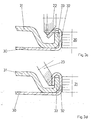
- FIGS 3a to 3d show the connection of a roof 30 with the frame 31 of a sliding roof.
- an opening is recessed, wherein the opening edge is placed to a flange 32 which extends approximately perpendicular to the surface of the roof 30.
- the frame 31 terminates in a web 33 which is parallel to the flange 32.
- the flange 32 is higher than the web 33, whereby a connection between the roof 30 and frame 31 can be made by the protruding part of the flange 32 is bent by 180 ° around the web 33 around. This is done in four folding operations, which are shown in the figures 3a to 3d gradually.
- the protruding part of the flange 32 is bent by about 45 °.
- a pair of roles is provided.
- the first pressure roller 8 interacts with the first counter roller 10.
- the first pressure roller 8 has a conically widening folding section 34, the conicity of which corresponds to the intended bending of the flange 32.
- a cylindrical portion of the first pressure roller 8 abuts against the flange 32.
- the first counter roller 10 runs along the web 33 on the inside. Thus, no forces are introduced into the frame 31 or into the roof 30.
- the second pressure roller 9 cooperates with a second counter roller 11.
- the second pressure roller 9 is a cylinder without a conical section.
- the slightly inclined second counter roller 11, also called folding roller, pushes the flange 32 by a further 45 °.
- a fourth pressure roller 21 or a fourth counter roller 23 is used;
- the fourth pair of rollers is either formed according to Figure 1 at a second Rollfalzkopf or is generated by rotation of the turret 24 according to Figure 2, wherein the fourth pressure roller 21 is again represented by the second pressure roller 9.
- the individual positions are achieved by always the entire Rollfalzkopf 1 is rotated and the carrier 4 is guided by means of the carriage 5 in the respective folding position.
- the invention therefore also relates to a method for folding the flange about the other, parallel thereto flange in at least two successive Steps, wherein at least in the first step, the mutually parallel flanges 32, 33 by moving a movable carriage 5 and arranged on the carriage 5 pressure roller 8, 9 or 20, 21 of the pressure roller 8, 9 or 20, 21 and a counter-roller against each other are pressed and the flange 32 is partially flanged, wherein in at least one subsequent step, the flange 32 is further crimped by a correspondingly aligned counter-roll.
- a tapered portion of the pressure roller takes care of the partial edging of the first step.
- the pressure roller essentially has the task to guide the Rollfalzkopf the flange, it may be a single cylindrical body which rests against the unrebated portion of the flange and rolls it. Each provided with a conical section counter rollers are aligned in each case according to the desired progress in the flanging to the flange.
Landscapes
- Engineering & Computer Science (AREA)
- Mechanical Engineering (AREA)
- Bending Of Plates, Rods, And Pipes (AREA)
- Roof Covering Using Slabs Or Stiff Sheets (AREA)
- Automobile Manufacture Line, Endless Track Vehicle, Trailer (AREA)
- Folding Of Thin Sheet-Like Materials, Special Discharging Devices, And Others (AREA)
- Manipulator (AREA)
- Press Drives And Press Lines (AREA)
- Body Structure For Vehicles (AREA)
- Shaping Of Tube Ends By Bending Or Straightening (AREA)
Claims (10)
- Tête roulante de pliage qui est destinée à être fixée sur le bras d'un robot et qui présente un corps de base (2), caractérisée par au moins deux paires de rouleaux (8, 10; 9, 11 ou 20, 22; 21, 23), chacune des au moins deux paires de rouleaux (8, 10; 9, 11 ou 20, 22; 21, 23) étant constituée d'un rouleau de poussée et d'un contre-rouleau qui coopèrent pour cintrer sur un angle défini une bride (32) le long d'une ligne de pliage, et un chariot (5) qui peut être déplacé sur le corps de base (2), les rouleaux de poussée (8, 9 ou 20, 21) étant montés à rotation sur le chariot (5).
- Tête roulante de pliage selon la revendication 1, caractérisée en ce que le deuxième contre-rouleau (1) d'une des paires de rouleaux (9, 11) est monté sur le corps de base (2) sans pouvoir coulisser et en ce que le premier contre-rouleau (10) de l'autre paire de rouleaux (8, 16) est monté à rotation sur un autre chariot (12) qui peut être déplacé par rapport au corps de base (2).
- Tête roulante de pliage selon la revendication 1, caractérisée en ce que les deux contre-rouleaux (10, 11) sont montés à rotation dans des paliers qui sont fixés sur le corps de base (2) sans pouvoir s'y déplacer.
- Tête roulante de pliage selon la revendication 2, caractérisée en ce que les deux chariots (5, 12) sont disposés de manière à pouvoir être déplacés perpendiculairement l'un à l'autre sur le corps de base (2).
- Tête roulante de pliage selon l'une des revendications précédentes, caractérisée en ce qu'un rouleau de poussée (9) peut être associé à différents contre-rouleaux (11, 22, 23).
- Tête roulante de pliage selon la revendication 5, caractérisée en ce que les différents contre-rouleaux (11, 22, 23) sont accouplés à une tête revolver (24) reliée au corps de base (2).
- Procédé de pliage d'une bride (32) par recours à une tête roulante de pliage selon la revendication 1, le rabattement des bords s'effectuant au moins en deux étapes successives, caractérisé en ce que la bride (32) est pliée autour d'une autre bride (33), tandis qu'au moins dans la première étape, les brides (32, 33) disposées parallèlement l'une à l'autre sont repoussées l'une contre l'autre par déplacement du chariot mobile (5) et du rouleau de poussée (8, 9 ou 20, 21) disposé sur le chariot (5) par le rouleau de poussée (8, 9 ou 20, 21) et le contre-rouleau, la bride (32) étant rabattue en partie, et que lors d'au moins une étape ultérieure, la bride (32) est rabattue davantage par un contre-rouleau orienté de manière appropriée.
- Procédé selon la revendication précédente, caractérisé en ce qu'une partie conique du rouleau de poussée (8, 9 ou 20, 21) assure le rabattement partiel (21).
- Procédé selon l'une des revendications précédentes, pour plier une bride (32) de 180° en quatre étapes, dans lequel au moins trois paires de rouleaux différentes de la tête roulante de pliage sont utilisées.
- Procédé selon la revendication précédente, caractérisé en ce que trois contre-rouleaux coopèrent successivement avec l'un des rouleaux de poussée pour former les au moins trois paires de rouleaux différentes.
Applications Claiming Priority (3)
| Application Number | Priority Date | Filing Date | Title |
|---|---|---|---|
| DE10142698 | 2001-08-31 | ||
| DE10142698 | 2001-08-31 | ||
| PCT/DE2002/003217 WO2003024641A1 (fr) | 2001-08-31 | 2002-08-29 | Tete de pliage a roulement et procede de pliage d'une bride |
Publications (2)
| Publication Number | Publication Date |
|---|---|
| EP1420908A1 EP1420908A1 (fr) | 2004-05-26 |
| EP1420908B1 true EP1420908B1 (fr) | 2006-06-07 |
Family
ID=7697260
Family Applications (1)
| Application Number | Title | Priority Date | Filing Date |
|---|---|---|---|
| EP02798687A Expired - Lifetime EP1420908B1 (fr) | 2001-08-31 | 2002-08-29 | Tete de pliage a roulement et procede de pliage d'une bride |
Country Status (8)
| Country | Link |
|---|---|
| US (1) | US7152292B2 (fr) |
| EP (1) | EP1420908B1 (fr) |
| JP (1) | JP4485196B2 (fr) |
| KR (1) | KR100883320B1 (fr) |
| AT (1) | ATE328682T1 (fr) |
| DE (2) | DE50207123D1 (fr) |
| ES (1) | ES2263848T3 (fr) |
| WO (1) | WO2003024641A1 (fr) |
Cited By (7)
| Publication number | Priority date | Publication date | Assignee | Title |
|---|---|---|---|---|
| WO2008068314A2 (fr) | 2006-12-08 | 2008-06-12 | Edag Gmbh & Co. Kgaa | Appareil à main de bordage |
| DE102007002856A1 (de) | 2007-01-15 | 2008-07-17 | Edag Gmbh & Co. Kgaa | Blechverbund, Verfahren zum Fügen von Blechen und Fügevorrichtung |
| DE102009024344A1 (de) | 2009-06-09 | 2010-12-30 | Edag Gmbh & Co. Kgaa | Verfahren und Werkzeug zum Bördeln eines Werkstücks |
| FR2955509A1 (fr) * | 2010-01-25 | 2011-07-29 | Peugeot Citroen Automobiles Sa | Dispositif d'assemblage de panneaux pour un vehicule automobile. |
| DE202015102477U1 (de) | 2015-05-13 | 2016-08-17 | Kuka Systems Gmbh | Falzwerkzeug |
| CN106363092A (zh) * | 2016-12-02 | 2017-02-01 | 烟台达源自动化科技有限公司 | 一种用于白车身天窗包边的滚轮机构 |
| DE102021130973A1 (de) | 2021-11-25 | 2023-05-25 | Ebz Systec Gmbh | Rollfalzkopf zum Befestigen an einem Roboterarm und System umfassend einen Rollfalzkopf und einen Roboter mit einem Roboterarm |
Families Citing this family (116)
| Publication number | Priority date | Publication date | Assignee | Title |
|---|---|---|---|---|
| DE10340509A1 (de) * | 2003-09-03 | 2005-03-31 | Bayerische Motoren Werke Ag | Keiltriebwerkzeug mit zueinander verstellbaren Elementen zum schneidlosen Formen eines Blechwerkstückes in einer Presse |
| EP1640080B1 (fr) * | 2004-09-24 | 2007-10-17 | EDAG Engineering + Design Aktiengesellschaft | Dispositif et méthode de sertissage avec protection de la pièce |
| US7124611B2 (en) | 2004-10-08 | 2006-10-24 | Valiant Corporation | Roller hemming machine |
| DE102005004474B3 (de) * | 2005-01-31 | 2006-08-31 | Edag Engineering + Design Ag | Bördelvorrichtung und Bördelverfahren zum Umlegen eines Bördelstegs eines Bauteils um eine Bördelkante |
| DE102005012310B3 (de) * | 2005-03-17 | 2006-10-12 | Daimlerchrysler Ag | Vorrichtung und Verfahren zum Falzen von Blech, insbesondere Karosserieblech |
| DE102005042362B4 (de) * | 2005-09-07 | 2007-06-06 | Audi Ag | Falzvorrichtung für einen Rollfalzkopf einer Rollfalzvorrichtung |
| ES2278538B1 (es) * | 2006-01-25 | 2008-05-01 | Mb Sistemas, S.Coop. | Sistema de engatillado por rodillo. |
| DE102006010469A1 (de) * | 2006-03-07 | 2007-09-13 | GM Global Technology Operations, Inc., Detroit | Bördeleinrichtung sowie Verfahren zum Rollbördeln von Werkstücken |
| DE102006014279A1 (de) | 2006-03-28 | 2007-10-04 | Edag Engineering + Design Ag | Spannvorrichtung zum Aufnehmen und Spannen von Bauteilen |
| EP1949981B1 (fr) * | 2007-01-18 | 2015-04-29 | Toyota Motor Corporation | Assemblage de pièces en tôle |
| DE202007007838U1 (de) | 2007-06-01 | 2007-09-13 | Edag Engineering + Design Ag | Rollbördelwerkzeug |
| KR100872601B1 (ko) * | 2008-03-14 | 2008-12-08 | (주)우신시스템 | 차량용 패널의 헤밍장치 |
| DE202009005111U1 (de) * | 2009-08-05 | 2010-12-30 | Kuka Systems Gmbh | Falzeinrichtung |
| SE534675C2 (sv) * | 2010-03-19 | 2011-11-15 | Bjarnes System Ab | Anordning för samtidig fastsättning och invikning av klammer för plåttak |
| JP5580682B2 (ja) * | 2010-07-22 | 2014-08-27 | 株式会社ヒロテック | ヘミング装置 |
| KR20170019366A (ko) | 2014-05-16 | 2017-02-21 | 디버전트 테크놀로지스, 인크. | 차량 섀시용 모듈형 성형 접속체 및 그 사용 방법 |
| JP6820843B2 (ja) | 2014-07-02 | 2021-01-27 | ダイバージェント テクノロジーズ, インコーポレイテッドDivergent Technologies, Inc. | 継手部材を製造するためのシステム及び方法 |
| KR20190006593A (ko) | 2016-06-09 | 2019-01-18 | 디버전트 테크놀로지스, 인크. | 아크 및 노드 설계 및 제조용 시스템들 및 방법들 |
| US11155005B2 (en) | 2017-02-10 | 2021-10-26 | Divergent Technologies, Inc. | 3D-printed tooling and methods for producing same |
| US10759090B2 (en) | 2017-02-10 | 2020-09-01 | Divergent Technologies, Inc. | Methods for producing panels using 3D-printed tooling shells |
| CN106825174B (zh) * | 2017-04-05 | 2019-05-10 | 上海德莘汽车工程技术有限公司 | 一种车门包边方法及设备 |
| US10898968B2 (en) | 2017-04-28 | 2021-01-26 | Divergent Technologies, Inc. | Scatter reduction in additive manufacturing |
| US12251884B2 (en) | 2017-04-28 | 2025-03-18 | Divergent Technologies, Inc. | Support structures in additive manufacturing |
| US10703419B2 (en) | 2017-05-19 | 2020-07-07 | Divergent Technologies, Inc. | Apparatus and methods for joining panels |
| US11358337B2 (en) | 2017-05-24 | 2022-06-14 | Divergent Technologies, Inc. | Robotic assembly of transport structures using on-site additive manufacturing |
| US11123973B2 (en) | 2017-06-07 | 2021-09-21 | Divergent Technologies, Inc. | Interconnected deflectable panel and node |
| US10919230B2 (en) | 2017-06-09 | 2021-02-16 | Divergent Technologies, Inc. | Node with co-printed interconnect and methods for producing same |
| US10781846B2 (en) | 2017-06-19 | 2020-09-22 | Divergent Technologies, Inc. | 3-D-printed components including fasteners and methods for producing same |
| US10994876B2 (en) | 2017-06-30 | 2021-05-04 | Divergent Technologies, Inc. | Automated wrapping of components in transport structures |
| US11022375B2 (en) | 2017-07-06 | 2021-06-01 | Divergent Technologies, Inc. | Apparatus and methods for additively manufacturing microtube heat exchangers |
| US10895315B2 (en) | 2017-07-07 | 2021-01-19 | Divergent Technologies, Inc. | Systems and methods for implementing node to node connections in mechanized assemblies |
| US10940609B2 (en) | 2017-07-25 | 2021-03-09 | Divergent Technologies, Inc. | Methods and apparatus for additively manufactured endoskeleton-based transport structures |
| US10751800B2 (en) | 2017-07-25 | 2020-08-25 | Divergent Technologies, Inc. | Methods and apparatus for additively manufactured exoskeleton-based transport structures |
| US10605285B2 (en) | 2017-08-08 | 2020-03-31 | Divergent Technologies, Inc. | Systems and methods for joining node and tube structures |
| US10357959B2 (en) | 2017-08-15 | 2019-07-23 | Divergent Technologies, Inc. | Methods and apparatus for additively manufactured identification features |
| US11306751B2 (en) | 2017-08-31 | 2022-04-19 | Divergent Technologies, Inc. | Apparatus and methods for connecting tubes in transport structures |
| US10960611B2 (en) | 2017-09-06 | 2021-03-30 | Divergent Technologies, Inc. | Methods and apparatuses for universal interface between parts in transport structures |
| US11292058B2 (en) | 2017-09-12 | 2022-04-05 | Divergent Technologies, Inc. | Apparatus and methods for optimization of powder removal features in additively manufactured components |
| US10668816B2 (en) | 2017-10-11 | 2020-06-02 | Divergent Technologies, Inc. | Solar extended range electric vehicle with panel deployment and emitter tracking |
| US10814564B2 (en) | 2017-10-11 | 2020-10-27 | Divergent Technologies, Inc. | Composite material inlay in additively manufactured structures |
| US11786971B2 (en) | 2017-11-10 | 2023-10-17 | Divergent Technologies, Inc. | Structures and methods for high volume production of complex structures using interface nodes |
| US10926599B2 (en) | 2017-12-01 | 2021-02-23 | Divergent Technologies, Inc. | Suspension systems using hydraulic dampers |
| US11110514B2 (en) | 2017-12-14 | 2021-09-07 | Divergent Technologies, Inc. | Apparatus and methods for connecting nodes to tubes in transport structures |
| US11085473B2 (en) | 2017-12-22 | 2021-08-10 | Divergent Technologies, Inc. | Methods and apparatus for forming node to panel joints |
| US11534828B2 (en) | 2017-12-27 | 2022-12-27 | Divergent Technologies, Inc. | Assembling structures comprising 3D printed components and standardized components utilizing adhesive circuits |
| US11420262B2 (en) | 2018-01-31 | 2022-08-23 | Divergent Technologies, Inc. | Systems and methods for co-casting of additively manufactured interface nodes |
| US10751934B2 (en) | 2018-02-01 | 2020-08-25 | Divergent Technologies, Inc. | Apparatus and methods for additive manufacturing with variable extruder profiles |
| US11224943B2 (en) | 2018-03-07 | 2022-01-18 | Divergent Technologies, Inc. | Variable beam geometry laser-based powder bed fusion |
| US11267236B2 (en) | 2018-03-16 | 2022-03-08 | Divergent Technologies, Inc. | Single shear joint for node-to-node connections |
| US11872689B2 (en) | 2018-03-19 | 2024-01-16 | Divergent Technologies, Inc. | End effector features for additively manufactured components |
| US11254381B2 (en) | 2018-03-19 | 2022-02-22 | Divergent Technologies, Inc. | Manufacturing cell based vehicle manufacturing system and method |
| US11408216B2 (en) | 2018-03-20 | 2022-08-09 | Divergent Technologies, Inc. | Systems and methods for co-printed or concurrently assembled hinge structures |
| US11613078B2 (en) | 2018-04-20 | 2023-03-28 | Divergent Technologies, Inc. | Apparatus and methods for additively manufacturing adhesive inlet and outlet ports |
| US11214317B2 (en) | 2018-04-24 | 2022-01-04 | Divergent Technologies, Inc. | Systems and methods for joining nodes and other structures |
| US11020800B2 (en) | 2018-05-01 | 2021-06-01 | Divergent Technologies, Inc. | Apparatus and methods for sealing powder holes in additively manufactured parts |
| US10682821B2 (en) | 2018-05-01 | 2020-06-16 | Divergent Technologies, Inc. | Flexible tooling system and method for manufacturing of composite structures |
| US11389816B2 (en) | 2018-05-09 | 2022-07-19 | Divergent Technologies, Inc. | Multi-circuit single port design in additively manufactured node |
| US10691104B2 (en) | 2018-05-16 | 2020-06-23 | Divergent Technologies, Inc. | Additively manufacturing structures for increased spray forming resolution or increased fatigue life |
| US11590727B2 (en) | 2018-05-21 | 2023-02-28 | Divergent Technologies, Inc. | Custom additively manufactured core structures |
| US11441586B2 (en) | 2018-05-25 | 2022-09-13 | Divergent Technologies, Inc. | Apparatus for injecting fluids in node based connections |
| US11035511B2 (en) | 2018-06-05 | 2021-06-15 | Divergent Technologies, Inc. | Quick-change end effector |
| US11292056B2 (en) | 2018-07-06 | 2022-04-05 | Divergent Technologies, Inc. | Cold-spray nozzle |
| US11269311B2 (en) | 2018-07-26 | 2022-03-08 | Divergent Technologies, Inc. | Spray forming structural joints |
| US10836120B2 (en) | 2018-08-27 | 2020-11-17 | Divergent Technologies, Inc . | Hybrid composite structures with integrated 3-D printed elements |
| US11433557B2 (en) | 2018-08-28 | 2022-09-06 | Divergent Technologies, Inc. | Buffer block apparatuses and supporting apparatuses |
| US11826953B2 (en) | 2018-09-12 | 2023-11-28 | Divergent Technologies, Inc. | Surrogate supports in additive manufacturing |
| US11072371B2 (en) | 2018-10-05 | 2021-07-27 | Divergent Technologies, Inc. | Apparatus and methods for additively manufactured structures with augmented energy absorption properties |
| US11260582B2 (en) | 2018-10-16 | 2022-03-01 | Divergent Technologies, Inc. | Methods and apparatus for manufacturing optimized panels and other composite structures |
| US12115583B2 (en) | 2018-11-08 | 2024-10-15 | Divergent Technologies, Inc. | Systems and methods for adhesive-based part retention features in additively manufactured structures |
| US12194536B2 (en) | 2018-11-13 | 2025-01-14 | Divergent Technologies, Inc. | 3-D printer with manifolds for gas exchange |
| US11504912B2 (en) | 2018-11-20 | 2022-11-22 | Divergent Technologies, Inc. | Selective end effector modular attachment device |
| USD911222S1 (en) | 2018-11-21 | 2021-02-23 | Divergent Technologies, Inc. | Vehicle and/or replica |
| US11529741B2 (en) | 2018-12-17 | 2022-12-20 | Divergent Technologies, Inc. | System and method for positioning one or more robotic apparatuses |
| US11449021B2 (en) | 2018-12-17 | 2022-09-20 | Divergent Technologies, Inc. | Systems and methods for high accuracy fixtureless assembly |
| US10663110B1 (en) | 2018-12-17 | 2020-05-26 | Divergent Technologies, Inc. | Metrology apparatus to facilitate capture of metrology data |
| US11885000B2 (en) | 2018-12-21 | 2024-01-30 | Divergent Technologies, Inc. | In situ thermal treatment for PBF systems |
| US12378643B2 (en) | 2019-01-18 | 2025-08-05 | Divergent Technologies, Inc. | Aluminum alloys |
| US11203240B2 (en) | 2019-04-19 | 2021-12-21 | Divergent Technologies, Inc. | Wishbone style control arm assemblies and methods for producing same |
| US12314031B1 (en) | 2019-06-27 | 2025-05-27 | Divergent Technologies, Inc. | Incorporating complex geometric features in additively manufactured parts |
| US12280554B2 (en) | 2019-11-21 | 2025-04-22 | Divergent Technologies, Inc. | Fixtureless robotic assembly |
| US11912339B2 (en) | 2020-01-10 | 2024-02-27 | Divergent Technologies, Inc. | 3-D printed chassis structure with self-supporting ribs |
| US11590703B2 (en) | 2020-01-24 | 2023-02-28 | Divergent Technologies, Inc. | Infrared radiation sensing and beam control in electron beam additive manufacturing |
| US11884025B2 (en) | 2020-02-14 | 2024-01-30 | Divergent Technologies, Inc. | Three-dimensional printer and methods for assembling parts via integration of additive and conventional manufacturing operations |
| US11479015B2 (en) | 2020-02-14 | 2022-10-25 | Divergent Technologies, Inc. | Custom formed panels for transport structures and methods for assembling same |
| US12194674B2 (en) | 2020-02-14 | 2025-01-14 | Divergent Technologies, Inc. | Multi-material powder bed fusion 3-D printer |
| US12203397B2 (en) | 2020-02-18 | 2025-01-21 | Divergent Technologies, Inc. | Impact energy absorber with integrated engine exhaust noise muffler |
| US11421577B2 (en) | 2020-02-25 | 2022-08-23 | Divergent Technologies, Inc. | Exhaust headers with integrated heat shielding and thermal syphoning |
| US11535322B2 (en) | 2020-02-25 | 2022-12-27 | Divergent Technologies, Inc. | Omni-positional adhesion device |
| US12337541B2 (en) | 2020-02-27 | 2025-06-24 | Divergent Technologies, Inc. | Powder bed fusion additive manufacturing system with desiccant positioned within hopper and ultrasonic transducer |
| US11413686B2 (en) | 2020-03-06 | 2022-08-16 | Divergent Technologies, Inc. | Methods and apparatuses for sealing mechanisms for realizing adhesive connections with additively manufactured components |
| KR20230035571A (ko) | 2020-06-10 | 2023-03-14 | 디버전트 테크놀로지스, 인크. | 적응형 생산 시스템 |
| US11850804B2 (en) | 2020-07-28 | 2023-12-26 | Divergent Technologies, Inc. | Radiation-enabled retention features for fixtureless assembly of node-based structures |
| US11806941B2 (en) | 2020-08-21 | 2023-11-07 | Divergent Technologies, Inc. | Mechanical part retention features for additively manufactured structures |
| WO2022055898A1 (fr) | 2020-09-08 | 2022-03-17 | Divergent Technologies, Inc. | Génération de séquence d'assemblage |
| WO2022066671A1 (fr) | 2020-09-22 | 2022-03-31 | Divergent Technologies, Inc. | Procédés et appareils destinés au broyage à boulets permettant de produire de la poudre pour la fabrication additive |
| US12220819B2 (en) | 2020-10-21 | 2025-02-11 | Divergent Technologies, Inc. | 3-D printed metrology feature geometry and detection |
| US12311612B2 (en) | 2020-12-18 | 2025-05-27 | Divergent Technologies, Inc. | Direct inject joint architecture enabled by quick cure adhesive |
| US12083596B2 (en) | 2020-12-21 | 2024-09-10 | Divergent Technologies, Inc. | Thermal elements for disassembly of node-based adhesively bonded structures |
| US12226824B2 (en) | 2020-12-22 | 2025-02-18 | Divergent Technologies, Inc. | Three dimensional printer with configurable build plate for rapid powder removal |
| US11872626B2 (en) | 2020-12-24 | 2024-01-16 | Divergent Technologies, Inc. | Systems and methods for floating pin joint design |
| US11947335B2 (en) | 2020-12-30 | 2024-04-02 | Divergent Technologies, Inc. | Multi-component structure optimization for combining 3-D printed and commercially available parts |
| US11928966B2 (en) | 2021-01-13 | 2024-03-12 | Divergent Technologies, Inc. | Virtual railroad |
| US12459377B2 (en) | 2021-01-19 | 2025-11-04 | Divergent Technologies, Inc. | Energy unit cells for primary vehicle structure |
| US12249812B2 (en) | 2021-01-19 | 2025-03-11 | Divergent Technologies, Inc. | Bus bars for printed structural electric battery modules |
| US11845130B2 (en) | 2021-03-09 | 2023-12-19 | Divergent Technologies, Inc. | Rotational additive manufacturing systems and methods |
| EP4326536A4 (fr) | 2021-04-23 | 2025-03-12 | Divergent Technologies, Inc. | Élimination de supports et d'autres matériaux à partir d'une surface et au sein de pièces imprimées en 3d creuses |
| US12138772B2 (en) | 2021-04-30 | 2024-11-12 | Divergent Technologies, Inc. | Mobile parts table |
| CN117769486A (zh) | 2021-05-24 | 2024-03-26 | 戴弗根特技术有限公司 | 机器人夹持器设备 |
| WO2023278878A1 (fr) | 2021-07-01 | 2023-01-05 | Divergent Technologies, Inc. | Composition d'alliage quasi-eutectique à base de al-mg-si pour des applications de résistance et de rigidité élevées |
| US12583033B2 (en) | 2021-08-13 | 2026-03-24 | Divergent Technologies, Inc. | Integrating additively-manufactured components |
| US11865617B2 (en) | 2021-08-25 | 2024-01-09 | Divergent Technologies, Inc. | Methods and apparatuses for wide-spectrum consumption of output of atomization processes across multi-process and multi-scale additive manufacturing modalities |
| US12351238B2 (en) | 2021-11-02 | 2025-07-08 | Divergent Technologies, Inc. | Motor nodes |
| US12152629B2 (en) | 2022-01-25 | 2024-11-26 | Divergent Technologies, Inc. | Attachment structure having a connection member with multiple attachment features |
| WO2023147390A2 (fr) | 2022-01-25 | 2023-08-03 | Divergent Technologies, Inc. | Corrections reposant sur des mesures pour ensemble structure |
| US12678974B2 (en) | 2022-01-25 | 2026-07-14 | Divergent Technologies, Inc. | Low deflection tooling apparatus |
| WO2024197198A2 (fr) | 2023-03-21 | 2024-09-26 | Divergent Technologies, Inc. | Capteur de force tangentielle pour étrier de frein |
Family Cites Families (10)
| Publication number | Priority date | Publication date | Assignee | Title |
|---|---|---|---|---|
| US3015293A (en) * | 1957-06-14 | 1962-01-02 | Fletcher L Parham | Seamer and method |
| US4470186A (en) * | 1981-05-11 | 1984-09-11 | Knudson Gary Art | Reversible seaming apparatus with laterally separable rollers having parallel axes |
| US4726107A (en) * | 1987-07-06 | 1988-02-23 | Knudson Gary Art | Seaming apparatus |
| JP2675347B2 (ja) * | 1988-09-06 | 1997-11-12 | マツダ株式会社 | ヘミング成形装置 |
| DE3916445A1 (de) * | 1989-05-20 | 1990-11-22 | Reinhardt Gmbh Maschbau | Falzmaschine, insbesondere zum verbinden der raender von blechen durch falzen |
| US5267387A (en) * | 1991-08-01 | 1993-12-07 | Triengineering Co., Ltd. | Method for hemming a workpiece having an upturned edge |
| EP0577876B1 (fr) | 1992-07-09 | 1996-09-04 | TRIENGINEERING Co., Ltd. | Appareil à rouleau pour joindre une pièce |
| DE29606725U1 (de) * | 1996-04-16 | 1996-08-14 | Trumpf Gmbh & Co, 71254 Ditzingen | Maschine zum Umbiegen eines Blechrandes |
| JP3563349B2 (ja) * | 1998-09-08 | 2004-09-08 | トライエンジニアリング株式会社 | ローラー転圧式加工装置及びローラー転圧式加工方法 |
| SE514087C2 (sv) * | 1999-04-19 | 2000-12-18 | Abb Ab | Förfarande vid sammanfogning |
-
2002
- 2002-08-29 KR KR1020047002870A patent/KR100883320B1/ko not_active Expired - Lifetime
- 2002-08-29 AT AT02798687T patent/ATE328682T1/de active
- 2002-08-29 JP JP2003528330A patent/JP4485196B2/ja not_active Expired - Lifetime
- 2002-08-29 EP EP02798687A patent/EP1420908B1/fr not_active Expired - Lifetime
- 2002-08-29 ES ES02798687T patent/ES2263848T3/es not_active Expired - Lifetime
- 2002-08-29 WO PCT/DE2002/003217 patent/WO2003024641A1/fr not_active Ceased
- 2002-08-29 DE DE50207123T patent/DE50207123D1/de not_active Expired - Lifetime
- 2002-08-29 DE DE20280246U patent/DE20280246U1/de not_active Expired - Lifetime
- 2002-08-29 US US10/487,726 patent/US7152292B2/en not_active Expired - Lifetime
Cited By (13)
| Publication number | Priority date | Publication date | Assignee | Title |
|---|---|---|---|---|
| WO2008068314A3 (fr) * | 2006-12-08 | 2008-07-24 | Edag Gmbh & Co Kgaa | Appareil à main de bordage |
| WO2008068314A2 (fr) | 2006-12-08 | 2008-06-12 | Edag Gmbh & Co. Kgaa | Appareil à main de bordage |
| DE102007002856B4 (de) * | 2007-01-15 | 2012-02-09 | Edag Gmbh & Co. Kgaa | Vorrichtung zum Bördeln und Schweißen oder Löten von Bauteilen |
| DE102007002856A1 (de) | 2007-01-15 | 2008-07-17 | Edag Gmbh & Co. Kgaa | Blechverbund, Verfahren zum Fügen von Blechen und Fügevorrichtung |
| WO2008086994A1 (fr) | 2007-01-15 | 2008-07-24 | Edag Gmbh & Co. Kgaa | Assemblage de tôles, procédé d'assemblage de tôles et dispositif d'assemblage |
| DE102009024344A1 (de) | 2009-06-09 | 2010-12-30 | Edag Gmbh & Co. Kgaa | Verfahren und Werkzeug zum Bördeln eines Werkstücks |
| DE102009024344B4 (de) * | 2009-06-09 | 2011-02-24 | Edag Gmbh & Co. Kgaa | Verfahren und Werkzeug zum Bördeln eines Werkstücks |
| FR2955509A1 (fr) * | 2010-01-25 | 2011-07-29 | Peugeot Citroen Automobiles Sa | Dispositif d'assemblage de panneaux pour un vehicule automobile. |
| DE202015102477U1 (de) | 2015-05-13 | 2016-08-17 | Kuka Systems Gmbh | Falzwerkzeug |
| CN106363092A (zh) * | 2016-12-02 | 2017-02-01 | 烟台达源自动化科技有限公司 | 一种用于白车身天窗包边的滚轮机构 |
| CN106363092B (zh) * | 2016-12-02 | 2018-06-15 | 烟台达源自动化科技有限公司 | 一种用于白车身天窗包边的滚轮机构 |
| DE102021130973A1 (de) | 2021-11-25 | 2023-05-25 | Ebz Systec Gmbh | Rollfalzkopf zum Befestigen an einem Roboterarm und System umfassend einen Rollfalzkopf und einen Roboter mit einem Roboterarm |
| EP4186610A1 (fr) | 2021-11-25 | 2023-05-31 | Ebz Systec GmbH | Tête de pliage à rouleaux destinée à être fixée à un bras de robot et système comprenant une tête de pliage à rouleaux et un robot doté d'un bras de robot |
Also Published As
| Publication number | Publication date |
|---|---|
| JP4485196B2 (ja) | 2010-06-16 |
| DE50207123D1 (de) | 2006-07-20 |
| ES2263848T3 (es) | 2006-12-16 |
| KR20040063115A (ko) | 2004-07-12 |
| WO2003024641A1 (fr) | 2003-03-27 |
| JP2005501740A (ja) | 2005-01-20 |
| US7152292B2 (en) | 2006-12-26 |
| US20050015955A1 (en) | 2005-01-27 |
| KR100883320B1 (ko) | 2009-02-11 |
| ATE328682T1 (de) | 2006-06-15 |
| DE20280246U1 (de) | 2004-07-15 |
| EP1420908A1 (fr) | 2004-05-26 |
Similar Documents
| Publication | Publication Date | Title |
|---|---|---|
| EP1420908A1 (fr) | Tete de pliage a roulement et procede de pliage d'une bride | |
| EP1640080B1 (fr) | Dispositif et méthode de sertissage avec protection de la pièce | |
| EP3154722B1 (fr) | Presse à cintrer munie d'une unité de cintrage et procédé de formage | |
| EP2806986B1 (fr) | Procédé et dispositif destinés à relier deux extrémités de bandes métalliques | |
| WO2013127628A1 (fr) | Tête de pliage à rouleaux et procédé pour le pliage par rouleaux à l'aide d'un ensemble de rouleaux tandem | |
| DE102007005354A1 (de) | Paneelbefestigungsverfahren und Paneelglied für ein Kraftfahrzeug | |
| AT514821A1 (de) | Biegepresse und Biegeverfahren | |
| EP1420907B1 (fr) | Methode de sertissage pour le rabattement d'un bord a sertir d'une piece par repliage a rouleaux avec au moins deux etapes de pliage | |
| DE202020002598U1 (de) | Biegemaschine zum Biegen eines Werkstücks aus Flachmaterial und Steuereinheit für eine solche Biegemaschine | |
| WO2016037821A1 (fr) | Unité de rabattement pour outil de rabattement | |
| DE202009005111U1 (de) | Falzeinrichtung | |
| WO2018055180A1 (fr) | Outil et machine-outil ainsi que procédé pour usiner des pièces en forme de panneaux | |
| EP3515619A1 (fr) | Outil, machine-outil et procédé d'usinage de pièces en forme de plaque | |
| DE102004016385B3 (de) | Rollfalzvorrichtung zum Verbinden der Plattenränder zweier Blechplatten mittels eines Falzrandes | |
| DE2531290A1 (de) | Verfahren zum biegen von kettengliedern und kettengliedbiegemaschine zur durchfuehrung des verfahrens | |
| EP3515625A1 (fr) | Outil et machine-outil ainsi que procédé d'usinage de pièces en forme de plaque, en particulier de tôles | |
| DE102016119435A1 (de) | Werkzeug und Werkzeugmaschine sowie Verfahren zum Bearbeiten von plattenförmigen Werkstücken | |
| EP4529994A1 (fr) | Procédé de fabrication d'un pli à l'aide d'une plieuse et plieuse adaptée à ce procédé | |
| DE60003947T2 (de) | Verfahren und vorrichtung zur herstellung von dosen | |
| DE10012277C1 (de) | Vorrichtung und Verfahren zum Falzen von Blechen | |
| DE102019119848A1 (de) | Werkzeug und Verfahren zum Bearbeiten von plattenförmigen Werkstücken, insbesondere Blechen | |
| DE102005042362B4 (de) | Falzvorrichtung für einen Rollfalzkopf einer Rollfalzvorrichtung | |
| EP4529995A1 (fr) | Procédé de fabrication d'une cavité avec une machine de pliage et machine de pliage adaptée à ce procédé | |
| EP4529993A1 (fr) | Procédé de fabrication d'un pli à l'aide d'une plieuse et plieuse adaptée à ce procédé | |
| WO1997039845A1 (fr) | Procede et dispositif de cintrage de profiles creux par enroulement sur une partie centrale |
Legal Events
| Date | Code | Title | Description |
|---|---|---|---|
| PUAI | Public reference made under article 153(3) epc to a published international application that has entered the european phase |
Free format text: ORIGINAL CODE: 0009012 |
|
| 17P | Request for examination filed |
Effective date: 20040224 |
|
| AK | Designated contracting states |
Kind code of ref document: A1 Designated state(s): AT BE BG CH CY CZ DE DK EE ES FI FR GB GR IE IT LI LU MC NL PT SE SK TR |
|
| AX | Request for extension of the european patent |
Extension state: AL LT LV MK RO SI |
|
| RIN1 | Information on inventor provided before grant (corrected) |
Inventor name: QUELL, EWALD Inventor name: HOHMANN, MANFRED Inventor name: BURZLAFF, MARC |
|
| 17Q | First examination report despatched |
Effective date: 20050324 |
|
| GRAP | Despatch of communication of intention to grant a patent |
Free format text: ORIGINAL CODE: EPIDOSNIGR1 |
|
| GRAS | Grant fee paid |
Free format text: ORIGINAL CODE: EPIDOSNIGR3 |
|
| GRAA | (expected) grant |
Free format text: ORIGINAL CODE: 0009210 |
|
| AK | Designated contracting states |
Kind code of ref document: B1 Designated state(s): AT BE BG CH CY CZ DE DK EE ES FI FR GB GR IE IT LI LU MC NL PT SE SK TR |
|
| PG25 | Lapsed in a contracting state [announced via postgrant information from national office to epo] |
Ref country code: IT Free format text: LAPSE BECAUSE OF FAILURE TO SUBMIT A TRANSLATION OF THE DESCRIPTION OR TO PAY THE FEE WITHIN THE PRESCRIBED TIME-LIMIT;WARNING: LAPSES OF ITALIAN PATENTS WITH EFFECTIVE DATE BEFORE 2007 MAY HAVE OCCURRED AT ANY TIME BEFORE 2007. THE CORRECT EFFECTIVE DATE MAY BE DIFFERENT FROM THE ONE RECORDED. Effective date: 20060607 Ref country code: GB Free format text: LAPSE BECAUSE OF FAILURE TO SUBMIT A TRANSLATION OF THE DESCRIPTION OR TO PAY THE FEE WITHIN THE PRESCRIBED TIME-LIMIT Effective date: 20060607 Ref country code: NL Free format text: LAPSE BECAUSE OF FAILURE TO SUBMIT A TRANSLATION OF THE DESCRIPTION OR TO PAY THE FEE WITHIN THE PRESCRIBED TIME-LIMIT Effective date: 20060607 Ref country code: IE Free format text: LAPSE BECAUSE OF FAILURE TO SUBMIT A TRANSLATION OF THE DESCRIPTION OR TO PAY THE FEE WITHIN THE PRESCRIBED TIME-LIMIT Effective date: 20060607 Ref country code: SK Free format text: LAPSE BECAUSE OF FAILURE TO SUBMIT A TRANSLATION OF THE DESCRIPTION OR TO PAY THE FEE WITHIN THE PRESCRIBED TIME-LIMIT Effective date: 20060607 Ref country code: FI Free format text: LAPSE BECAUSE OF FAILURE TO SUBMIT A TRANSLATION OF THE DESCRIPTION OR TO PAY THE FEE WITHIN THE PRESCRIBED TIME-LIMIT Effective date: 20060607 |
|
| REG | Reference to a national code |
Ref country code: GB Ref legal event code: FG4D Free format text: NOT ENGLISH |
|
| REG | Reference to a national code |
Ref country code: CH Ref legal event code: EP |
|
| REG | Reference to a national code |
Ref country code: IE Ref legal event code: FG4D Free format text: LANGUAGE OF EP DOCUMENT: GERMAN |
|
| REF | Corresponds to: |
Ref document number: 50207123 Country of ref document: DE Date of ref document: 20060720 Kind code of ref document: P |
|
| PG25 | Lapsed in a contracting state [announced via postgrant information from national office to epo] |
Ref country code: MC Free format text: LAPSE BECAUSE OF NON-PAYMENT OF DUE FEES Effective date: 20060831 Ref country code: LI Free format text: LAPSE BECAUSE OF NON-PAYMENT OF DUE FEES Effective date: 20060831 Ref country code: CH Free format text: LAPSE BECAUSE OF NON-PAYMENT OF DUE FEES Effective date: 20060831 |
|
| PG25 | Lapsed in a contracting state [announced via postgrant information from national office to epo] |
Ref country code: DK Free format text: LAPSE BECAUSE OF FAILURE TO SUBMIT A TRANSLATION OF THE DESCRIPTION OR TO PAY THE FEE WITHIN THE PRESCRIBED TIME-LIMIT Effective date: 20060907 Ref country code: SE Free format text: LAPSE BECAUSE OF FAILURE TO SUBMIT A TRANSLATION OF THE DESCRIPTION OR TO PAY THE FEE WITHIN THE PRESCRIBED TIME-LIMIT Effective date: 20060907 |
|
| PG25 | Lapsed in a contracting state [announced via postgrant information from national office to epo] |
Ref country code: PT Free format text: LAPSE BECAUSE OF FAILURE TO SUBMIT A TRANSLATION OF THE DESCRIPTION OR TO PAY THE FEE WITHIN THE PRESCRIBED TIME-LIMIT Effective date: 20061107 |
|
| NLV1 | Nl: lapsed or annulled due to failure to fulfill the requirements of art. 29p and 29m of the patents act | ||
| REG | Reference to a national code |
Ref country code: ES Ref legal event code: FG2A Ref document number: 2263848 Country of ref document: ES Kind code of ref document: T3 |
|
| ET | Fr: translation filed | ||
| GBV | Gb: ep patent (uk) treated as always having been void in accordance with gb section 77(7)/1977 [no translation filed] |
Effective date: 20060607 |
|
| REG | Reference to a national code |
Ref country code: IE Ref legal event code: FD4D |
|
| PLBE | No opposition filed within time limit |
Free format text: ORIGINAL CODE: 0009261 |
|
| REG | Reference to a national code |
Ref country code: CH Ref legal event code: PL |
|
| STAA | Information on the status of an ep patent application or granted ep patent |
Free format text: STATUS: NO OPPOSITION FILED WITHIN TIME LIMIT |
|
| 26N | No opposition filed |
Effective date: 20070308 |
|
| PG25 | Lapsed in a contracting state [announced via postgrant information from national office to epo] |
Ref country code: GR Free format text: LAPSE BECAUSE OF FAILURE TO SUBMIT A TRANSLATION OF THE DESCRIPTION OR TO PAY THE FEE WITHIN THE PRESCRIBED TIME-LIMIT Effective date: 20060908 |
|
| PG25 | Lapsed in a contracting state [announced via postgrant information from national office to epo] |
Ref country code: BG Free format text: LAPSE BECAUSE OF FAILURE TO SUBMIT A TRANSLATION OF THE DESCRIPTION OR TO PAY THE FEE WITHIN THE PRESCRIBED TIME-LIMIT Effective date: 20060907 Ref country code: EE Free format text: LAPSE BECAUSE OF FAILURE TO SUBMIT A TRANSLATION OF THE DESCRIPTION OR TO PAY THE FEE WITHIN THE PRESCRIBED TIME-LIMIT Effective date: 20060607 |
|
| PG25 | Lapsed in a contracting state [announced via postgrant information from national office to epo] |
Ref country code: LU Free format text: LAPSE BECAUSE OF NON-PAYMENT OF DUE FEES Effective date: 20060829 Ref country code: TR Free format text: LAPSE BECAUSE OF FAILURE TO SUBMIT A TRANSLATION OF THE DESCRIPTION OR TO PAY THE FEE WITHIN THE PRESCRIBED TIME-LIMIT Effective date: 20060607 |
|
| PG25 | Lapsed in a contracting state [announced via postgrant information from national office to epo] |
Ref country code: CY Free format text: LAPSE BECAUSE OF FAILURE TO SUBMIT A TRANSLATION OF THE DESCRIPTION OR TO PAY THE FEE WITHIN THE PRESCRIBED TIME-LIMIT Effective date: 20060607 |
|
| BECH | Be: change of holder |
Owner name: FFT EDAG PRODUKTIONSSYSTEME G.M.B.H. Effective date: 20120330 |
|
| REG | Reference to a national code |
Ref country code: FR Ref legal event code: CD Owner name: FFT EDAG PRODUKTIONSSYSTEME GMBH & CO. KG, DE Effective date: 20120329 Ref country code: FR Ref legal event code: TP Owner name: FFT EDAG PRODUKTIONSSYSTEME GMBH & CO. KG, DE Effective date: 20120329 Ref country code: FR Ref legal event code: CJ Effective date: 20120329 |
|
| REG | Reference to a national code |
Ref country code: DE Ref legal event code: R082 Ref document number: 50207123 Country of ref document: DE Representative=s name: SCHWABE SANDMAIR MARX, DE |
|
| REG | Reference to a national code |
Ref country code: DE Ref legal event code: R082 Ref document number: 50207123 Country of ref document: DE Representative=s name: SCHWABE SANDMAIR MARX, DE Effective date: 20120713 Ref country code: DE Ref legal event code: R081 Ref document number: 50207123 Country of ref document: DE Owner name: FFT EDAG PRODUKTIONSSYSTEME GMBH & CO. KG, DE Free format text: FORMER OWNER: EDAG GMBH & CO. KGAA, 36039 FULDA, DE Effective date: 20120713 Ref country code: DE Ref legal event code: R082 Ref document number: 50207123 Country of ref document: DE Representative=s name: SCHWABE SANDMAIR MARX PATENTANWAELTE RECHTSANW, DE Effective date: 20120713 |
|
| REG | Reference to a national code |
Ref country code: AT Ref legal event code: PC Ref document number: 328682 Country of ref document: AT Kind code of ref document: T Owner name: FFT EDAG PRODUKTIONSSYSTEME GMBH & CO. KG, DE Effective date: 20120920 |
|
| REG | Reference to a national code |
Ref country code: ES Ref legal event code: PC2A Owner name: FFT EDAG PRODUKTIONSSYSTEME GMBH & CO. Effective date: 20121107 |
|
| REG | Reference to a national code |
Ref country code: FR Ref legal event code: PLFP Year of fee payment: 15 |
|
| REG | Reference to a national code |
Ref country code: FR Ref legal event code: PLFP Year of fee payment: 16 |
|
| REG | Reference to a national code |
Ref country code: FR Ref legal event code: PLFP Year of fee payment: 17 |
|
| PGFP | Annual fee paid to national office [announced via postgrant information from national office to epo] |
Ref country code: CZ Payment date: 20210824 Year of fee payment: 20 Ref country code: AT Payment date: 20210818 Year of fee payment: 20 Ref country code: FR Payment date: 20210823 Year of fee payment: 20 |
|
| PGFP | Annual fee paid to national office [announced via postgrant information from national office to epo] |
Ref country code: BE Payment date: 20210823 Year of fee payment: 20 Ref country code: DE Payment date: 20210819 Year of fee payment: 20 Ref country code: ES Payment date: 20210917 Year of fee payment: 20 |
|
| REG | Reference to a national code |
Ref country code: DE Ref legal event code: R071 Ref document number: 50207123 Country of ref document: DE |
|
| REG | Reference to a national code |
Ref country code: ES Ref legal event code: FD2A Effective date: 20220905 |
|
| REG | Reference to a national code |
Ref country code: BE Ref legal event code: MK Effective date: 20220829 |
|
| REG | Reference to a national code |
Ref country code: AT Ref legal event code: MK07 Ref document number: 328682 Country of ref document: AT Kind code of ref document: T Effective date: 20220829 |
|
| PG25 | Lapsed in a contracting state [announced via postgrant information from national office to epo] |
Ref country code: ES Free format text: LAPSE BECAUSE OF EXPIRATION OF PROTECTION Effective date: 20220830 Ref country code: CZ Free format text: LAPSE BECAUSE OF EXPIRATION OF PROTECTION Effective date: 20220829 |