EP1421418B1 - Erbiumdotierte optische verstärkungsfaser mit hoher absorption - Google Patents
Erbiumdotierte optische verstärkungsfaser mit hoher absorption Download PDFInfo
- Publication number
- EP1421418B1 EP1421418B1 EP02756808.8A EP02756808A EP1421418B1 EP 1421418 B1 EP1421418 B1 EP 1421418B1 EP 02756808 A EP02756808 A EP 02756808A EP 1421418 B1 EP1421418 B1 EP 1421418B1
- Authority
- EP
- European Patent Office
- Prior art keywords
- range
- fiber
- optical
- refractive index
- core region
- Prior art date
- Legal status (The legal status is an assumption and is not a legal conclusion. Google has not performed a legal analysis and makes no representation as to the accuracy of the status listed.)
- Expired - Lifetime
Links
- 238000010521 absorption reaction Methods 0.000 title claims description 9
- 239000013307 optical fiber Substances 0.000 title claims description 5
- 229910052691 Erbium Inorganic materials 0.000 title description 18
- UYAHIZSMUZPPFV-UHFFFAOYSA-N erbium Chemical compound [Er] UYAHIZSMUZPPFV-UHFFFAOYSA-N 0.000 title description 17
- 239000000835 fiber Substances 0.000 claims description 79
- 230000003287 optical effect Effects 0.000 claims description 63
- YBMRDBCBODYGJE-UHFFFAOYSA-N germanium dioxide Chemical compound O=[Ge]=O YBMRDBCBODYGJE-UHFFFAOYSA-N 0.000 claims description 15
- 238000004891 communication Methods 0.000 claims description 11
- 230000005540 biological transmission Effects 0.000 claims description 10
- PNEYBMLMFCGWSK-UHFFFAOYSA-N aluminium oxide Inorganic materials [O-2].[O-2].[O-2].[Al+3].[Al+3] PNEYBMLMFCGWSK-UHFFFAOYSA-N 0.000 claims description 7
- 230000007423 decrease Effects 0.000 claims description 4
- VQCBHWLJZDBHOS-UHFFFAOYSA-N erbium(III) oxide Inorganic materials O=[Er]O[Er]=O VQCBHWLJZDBHOS-UHFFFAOYSA-N 0.000 claims description 4
- 229910052593 corundum Inorganic materials 0.000 claims description 3
- 230000005855 radiation Effects 0.000 claims description 3
- 229910001845 yogo sapphire Inorganic materials 0.000 claims description 3
- VYPSYNLAJGMNEJ-UHFFFAOYSA-N Silicium dioxide Chemical compound O=[Si]=O VYPSYNLAJGMNEJ-UHFFFAOYSA-N 0.000 description 12
- 239000006185 dispersion Substances 0.000 description 7
- 239000000377 silicon dioxide Substances 0.000 description 6
- 238000000034 method Methods 0.000 description 5
- 230000000694 effects Effects 0.000 description 4
- 239000011521 glass Substances 0.000 description 4
- 239000000654 additive Substances 0.000 description 3
- 230000000996 additive effect Effects 0.000 description 3
- 230000003321 amplification Effects 0.000 description 3
- 239000000463 material Substances 0.000 description 3
- 238000003199 nucleic acid amplification method Methods 0.000 description 3
- 238000006243 chemical reaction Methods 0.000 description 2
- 238000010586 diagram Methods 0.000 description 2
- 230000010354 integration Effects 0.000 description 2
- 230000009022 nonlinear effect Effects 0.000 description 2
- 238000004806 packaging method and process Methods 0.000 description 2
- 230000008569 process Effects 0.000 description 2
- 230000000171 quenching effect Effects 0.000 description 2
- 230000009467 reduction Effects 0.000 description 2
- 229910052692 Dysprosium Inorganic materials 0.000 description 1
- 238000005229 chemical vapour deposition Methods 0.000 description 1
- 238000005253 cladding Methods 0.000 description 1
- 230000003247 decreasing effect Effects 0.000 description 1
- 238000000151 deposition Methods 0.000 description 1
- 230000008021 deposition Effects 0.000 description 1
- 238000009826 distribution Methods 0.000 description 1
- 239000002019 doping agent Substances 0.000 description 1
- KBQHZAAAGSGFKK-UHFFFAOYSA-N dysprosium atom Chemical compound [Dy] KBQHZAAAGSGFKK-UHFFFAOYSA-N 0.000 description 1
- 230000005684 electric field Effects 0.000 description 1
- 230000005281 excited state Effects 0.000 description 1
- 230000001747 exhibiting effect Effects 0.000 description 1
- 239000002360 explosive Substances 0.000 description 1
- 239000003365 glass fiber Substances 0.000 description 1
- 239000000146 host glass Substances 0.000 description 1
- 230000003993 interaction Effects 0.000 description 1
- 230000009021 linear effect Effects 0.000 description 1
- 238000004519 manufacturing process Methods 0.000 description 1
- 239000006089 photosensitive glass Substances 0.000 description 1
- 230000010287 polarization Effects 0.000 description 1
- 230000000644 propagated effect Effects 0.000 description 1
- 238000010791 quenching Methods 0.000 description 1
- 230000008054 signal transmission Effects 0.000 description 1
- 230000003595 spectral effect Effects 0.000 description 1
- 238000004611 spectroscopical analysis Methods 0.000 description 1
- 238000001228 spectrum Methods 0.000 description 1
- 238000010998 test method Methods 0.000 description 1
- 230000007704 transition Effects 0.000 description 1
- 238000007740 vapor deposition Methods 0.000 description 1
Images

Classifications
-
- H—ELECTRICITY
- H01—ELECTRIC ELEMENTS
- H01S—DEVICES USING THE PROCESS OF LIGHT AMPLIFICATION BY STIMULATED EMISSION OF RADIATION [LASER] TO AMPLIFY OR GENERATE LIGHT; DEVICES USING STIMULATED EMISSION OF ELECTROMAGNETIC RADIATION IN WAVE RANGES OTHER THAN OPTICAL
- H01S3/00—Lasers, i.e. devices using stimulated emission of electromagnetic radiation in the infrared, visible or ultraviolet wave range
- H01S3/05—Construction or shape of optical resonators; Accommodation of active medium therein; Shape of active medium
- H01S3/06—Construction or shape of active medium
- H01S3/063—Waveguide lasers, i.e. whereby the dimensions of the waveguide are of the order of the light wavelength
- H01S3/067—Fibre lasers
- H01S3/06708—Constructional details of the fibre, e.g. compositions, cross-section, shape or tapering
- H01S3/06716—Fibre compositions or doping with active elements
-
- C—CHEMISTRY; METALLURGY
- C03—GLASS; MINERAL OR SLAG WOOL
- C03C—CHEMICAL COMPOSITION OF GLASSES, GLAZES OR VITREOUS ENAMELS; SURFACE TREATMENT OF GLASS; SURFACE TREATMENT OF FIBRES OR FILAMENTS MADE FROM GLASS, MINERALS OR SLAGS; JOINING GLASS TO GLASS OR OTHER MATERIALS
- C03C13/00—Fibre or filament compositions
- C03C13/04—Fibre optics, e.g. core and clad fibre compositions
-
- C—CHEMISTRY; METALLURGY
- C03—GLASS; MINERAL OR SLAG WOOL
- C03C—CHEMICAL COMPOSITION OF GLASSES, GLAZES OR VITREOUS ENAMELS; SURFACE TREATMENT OF GLASS; SURFACE TREATMENT OF FIBRES OR FILAMENTS MADE FROM GLASS, MINERALS OR SLAGS; JOINING GLASS TO GLASS OR OTHER MATERIALS
- C03C13/00—Fibre or filament compositions
- C03C13/04—Fibre optics, e.g. core and clad fibre compositions
- C03C13/045—Silica-containing oxide glass compositions
- C03C13/046—Multicomponent glass compositions
-
- G—PHYSICS
- G02—OPTICS
- G02B—OPTICAL ELEMENTS, SYSTEMS OR APPARATUS
- G02B6/00—Light guides; Structural details of arrangements comprising light guides and other optical elements, e.g. couplings
- G02B6/02—Optical fibres with cladding with or without a coating
- G02B6/028—Optical fibres with cladding with or without a coating with core or cladding having graded refractive index
- G02B6/0283—Graded index region external to the central core segment, e.g. sloping layer or triangular or trapezoidal layer
- G02B6/0285—Graded index layer adjacent to the central core segment and ending at the outer cladding index
-
- H—ELECTRICITY
- H01—ELECTRIC ELEMENTS
- H01S—DEVICES USING THE PROCESS OF LIGHT AMPLIFICATION BY STIMULATED EMISSION OF RADIATION [LASER] TO AMPLIFY OR GENERATE LIGHT; DEVICES USING STIMULATED EMISSION OF ELECTROMAGNETIC RADIATION IN WAVE RANGES OTHER THAN OPTICAL
- H01S3/00—Lasers, i.e. devices using stimulated emission of electromagnetic radiation in the infrared, visible or ultraviolet wave range
- H01S3/05—Construction or shape of optical resonators; Accommodation of active medium therein; Shape of active medium
- H01S3/06—Construction or shape of active medium
- H01S3/063—Waveguide lasers, i.e. whereby the dimensions of the waveguide are of the order of the light wavelength
- H01S3/067—Fibre lasers
-
- G—PHYSICS
- G02—OPTICS
- G02B—OPTICAL ELEMENTS, SYSTEMS OR APPARATUS
- G02B6/00—Light guides; Structural details of arrangements comprising light guides and other optical elements, e.g. couplings
- G02B6/02—Optical fibres with cladding with or without a coating
- G02B6/02004—Optical fibres with cladding with or without a coating characterised by the core effective area or mode field radius
-
- G—PHYSICS
- G02—OPTICS
- G02B—OPTICAL ELEMENTS, SYSTEMS OR APPARATUS
- G02B6/00—Light guides; Structural details of arrangements comprising light guides and other optical elements, e.g. couplings
- G02B6/02—Optical fibres with cladding with or without a coating
- G02B6/02214—Optical fibres with cladding with or without a coating tailored to obtain the desired dispersion, e.g. dispersion shifted, dispersion flattened
- G02B6/02285—Characterised by the polarisation mode dispersion [PMD] properties, e.g. for minimising PMD
-
- H—ELECTRICITY
- H01—ELECTRIC ELEMENTS
- H01S—DEVICES USING THE PROCESS OF LIGHT AMPLIFICATION BY STIMULATED EMISSION OF RADIATION [LASER] TO AMPLIFY OR GENERATE LIGHT; DEVICES USING STIMULATED EMISSION OF ELECTROMAGNETIC RADIATION IN WAVE RANGES OTHER THAN OPTICAL
- H01S3/00—Lasers, i.e. devices using stimulated emission of electromagnetic radiation in the infrared, visible or ultraviolet wave range
- H01S3/05—Construction or shape of optical resonators; Accommodation of active medium therein; Shape of active medium
- H01S3/06—Construction or shape of active medium
- H01S3/063—Waveguide lasers, i.e. whereby the dimensions of the waveguide are of the order of the light wavelength
- H01S3/067—Fibre lasers
- H01S3/06708—Constructional details of the fibre, e.g. compositions, cross-section, shape or tapering
- H01S3/06729—Peculiar transverse fibre profile
-
- H—ELECTRICITY
- H01—ELECTRIC ELEMENTS
- H01S—DEVICES USING THE PROCESS OF LIGHT AMPLIFICATION BY STIMULATED EMISSION OF RADIATION [LASER] TO AMPLIFY OR GENERATE LIGHT; DEVICES USING STIMULATED EMISSION OF ELECTROMAGNETIC RADIATION IN WAVE RANGES OTHER THAN OPTICAL
- H01S3/00—Lasers, i.e. devices using stimulated emission of electromagnetic radiation in the infrared, visible or ultraviolet wave range
- H01S3/14—Lasers, i.e. devices using stimulated emission of electromagnetic radiation in the infrared, visible or ultraviolet wave range characterised by the material used as the active medium
- H01S3/16—Solid materials
- H01S3/1601—Solid materials characterised by an active (lasing) ion
- H01S3/1603—Solid materials characterised by an active (lasing) ion rare earth
- H01S3/1608—Solid materials characterised by an active (lasing) ion rare earth erbium
Definitions
- the present invention is directed to an optical waveguide amplifier for use in telecommunication systems and more particularly, an optical waveguide amplifying fiber providing high absorption and efficiency.
- the continuous growth of bandwidth requirements in optical-based communication systems has resulted in a large demand for systems able to operate within several optical wavelength ranges including the S-band optical range, the C-band optical range and the L-band optical range.
- the S-band is typically defined as the wavelengths between about 1465 nm and about 1525 nm, which lies below the C-band wavelength range which extends between about 1525 nm and about 1570 nm, which in turn lies just below the L-band wavelength range which extends between about 1570 nm and 1605 nm.
- system designers have begun to investigate those spectral regions lying beyond the conventional or C-band transmission band, including the aforementioned S-band and L-band wavelength ranges.
- Erbium-doped fiber amplifiers are used to provide amplification in optical transmission systems, and particularly for deployment within those systems operating within the C-band wavelength range.
- Application of erbium doped fiber amplifiers within the telecommunication systems operating within the L-band wavelength range can be problematic in that lower excited-state population inversions are necessary to provide sufficiently flat gain spectra across the L-band wavelength range.
- longer lengths of fiber within the erbium doped fiber amplifier or higher erbium concentrations therein are necessary to provide the same gain which would be provided within a given erbium doped fiber amplifier operating within the C-band wavelength range.
- the longer lengths of fiber required in erbium doped fiber amplifiers utilized within the L-band wavelength range results in a decrease in fiber efficiency and an increase in noise when compared with erbium doped fiber amplifiers.
- non-linear effects such as four-wave mixing and cross talk modulation are more severe.
- the effective areas of erbium doped fiber amplifiers are increased in an attempt to improve the "linearity" of the erbium doped fiber amplifiers.
- the reasoning for this approach has been that an increase in the effective area spreads out the optical power being transmitted through the doped region of the associated erbium doped fiber amplifier, thereby reducing the intensity of the optical power at any given point. This, in turn, yields an erbium doped fiber amplifier exhibiting more linear material behavior.
- the spectroscopy of erbium within L-band erbium doped fiber amplifiers thus poses several challenges with respect to designing the fiber amplifier to be used therein. These challenges include: (1) packaging amplifier modules with longer fiber lengths, as required by the lower differential gain while controlling fiber bend losses at longer wavelengths, (2) maintaining a high absorption rate without significantly increasing concentration quenching, (3) minimizing non-linear effects such as two-channel four-wave mixing and cross-phase modulation in the amplifier, and (4) minimizing the intrinsically higher L-band noise figure.
- US 5,412,672 relates to optical waveguides e.g.
- fibres for use as photonic amplifiers having a path region partly or wholly composed of a silica/germania glass with 0.1 to 5000 ppm mole of Er 3+ as a lasing additive and alumina to adjust the bandwidth, the Ge:Al mole ratio being more than 2.8, e.g. 1:0.001 to 0.25. It is stated that low amounts of alumina have a useful and significant effect on the lasing bandwidth whereby frequency division multiplex is facilitated.
- US 5,278,850 discloses fibres for use as photonic amplifiers that have a path region partly or, preferably, wholly composed as a silica/germania glass with 0.1 to 5000 ppm mole of Er 3+ as a lasing additive and alumina to adjust the bandwidth, the Ge:AI mole ratio being more than 2.8, e.g. 1:0.001 to 0.25.
- WO 01/39339 teaches an optical fiber for amplifying optical signals of 1.57 to 1.62 ⁇ m using an erbium doped core.
- EP 469 795 teaches a Si-based amplifier fiber with a core of Ge, Al and Er.
- US 5,278,850 teaches an optical fiber with Er3+as a lasing additive, alumina and germania.
- US 5,005,175 teaches an Er-doped fiber amplifier.
- US 5,027,079 likewise teaches an Er-doped fiber amplifier.
- US 5,259,046 teaches a doped optical waveguide amplifier in which the dopant, for example Er, has an annular distribution.
- US 5, 881,197 teaches a fiber with a cladding around a core, with an annular region of photosensitive glass.
- US 5,973,824 teaches an amplification method with a single mode glass fiber including dysprosium.
- This invention relates to an optical waveguide fiber amplifier that effects amplification of an optical signal within the L-band optical wavelength range. More specifically, the invention relates to a high efficiency optical waveguide amplifier operating in the L-band optical wavelength range providing reduced non-linearity effects and a reduced noise figure.
- the present invention provides an optical waveguide fiber according to claim 1.
- the amounts of Er 2 O 3 , Al 2 O 3 and GeO 2 within the core region and the refractive index profiles of the core region, the inner clad and the outer clad were selected to provide a mode field diameter of freater than or equal to 5.2 ⁇ m at a wavelength of 1550 nm.
- the present invention also includes optical communication systems employing the optical waveguide fibers and optical waveguide fiber amplifiers in accordance with the embodiments described above.
- the radii of the segments of the core is defined in terms of the index of refraction of the material of which the segment is made.
- a particular segment has a first and a last refractive index point.
- a central segment has an inner radius of zero because the first point of the segment is on the center line.
- the outer radius of the central segment is the radius drawn from the waveguide center line to the last point of the refractive index of the central segment.
- the radius of the waveguide center line to the location of its first refractive index point is the inner radius of that segment.
- the radius from the waveguide center line to the location of the last refractive index point of the segment is the outer radius of that segment.
- segment radii may be conveniently defined in a number of ways. In this application, radii are defined in accord with the figures, described in detail below.
- segment radius and refractive index used to describe refractive index profile, in no way limit the invention.
- refractive index profile or index profile is the relation between ⁇ % or refractive index and radius over a selected segment of the core.
- Total dispersion is defined as the algebraic sum of waveguide dispersion and material dispersion. Total dispersion is also referred to as chromatic dispersion in the art.
- Total background loss is defined as all optical loss not attributable to absorption from the 4ll3/2 to the 4llsl2 erbium transition, including scattering, host glass absorption, bend loss, concentration quenching effects, Hawking radiation, and similar phenomena.
- Cut-off wavelength is the coiled cut-off wavelength measured via the Telecommunications Industry Association/Electronic Industry Alliance standard test procedure (TIA/EIA-455-80B) as included within Recommended Standard, wherein the large bend diameter is 32 mm and the small bend diameter is 8 mm.
- the nonlinear process of four-wave mixing within erbium doped fiber amplifiers is generally approximated herein as, P FWM ⁇ n ⁇ k ⁇
- P FWM is the power of the mixing tones
- ⁇ k is the phase matching of the signals
- a eff is the effective area of the fiber amplifier
- X is the peak signal power density
- P 1 P 2 P 3 * are the power of the signals
- l is the effective interaction length of the signals.
- the phase matching n ( ⁇ k) is determined by chromatic dispersion along the fiber.
- Two-toned, four-wave mixing power conversion frequency is defined as the ratio of the output power in a four-wave mixing side band channel to the input in one of the two signal channels.
- the overlap of an optical waveguide fiber is generally defined as the proportion of the guided light within the fiber that interacts with a particular segment, such as an erbium doped core region or segment.
- the optical waveguide amplifying fiber described and disclosed herein has a generally segmented structure, as shown in Fig. 1 .
- Each of the segments is described by a refractive index profile, relative refractive index percent, ⁇ i, and an outside radius, r i .
- the subscript i for the r and ⁇ refers to a particular segment.
- the segments are numbered r 1 through r c beginning with the innermost segment which includes the waveguide longitudinal axis center line.
- a clad layer having a refractive index of n c surrounds the optical waveguide fiber.
- an optical waveguide amplifying fiber 10 includes a core region or segment 12 having an outer radius r 1 , an inner clad 14 having an outer radius r 2 and an outer clad 16 having an outer radius r c .
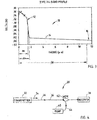
- FIG. 2 A general representation of the core refractive index profile of fiber 10 is illustrated in Fig. 2 , which shows relative refractive index percent charted versus the waveguide fiber amplifier radius. Although Fig. 2 shows only three discreet segments, it is understood that the functional requirements may be met by forming an optical waveguide fiber amplifier having more than three segments. However, embodiments having fewer segments are usually easier to manufacture and are therefore preferred. Further, the illustrated core index profile has a step index region, however, other indices may be utilized.
- the fiber 10 may be constructed via a variety of methods including, but in no way limited to, vapor axial deposition (VAD), modified chemical vapor deposition (MCVD) and outside vapor deposition (OVD). Fiber 10 is preferably constructed via an OVD process.
- VAD vapor axial deposition
- MCVD modified chemical vapor deposition
- OLED outside vapor deposition
- the core region 12 of optical waveguide fiber 10 is composed of a silica based glass and is at least in part comprised of Er 2 0 3 , within the range of from about 1300 wt.ppm to about 3600 wt.ppm, preferably within the range of from about 1950 wt.ppm to about 3100 wt.ppm, and most preferably within the range of from about 2200 wt.ppm to about 3000 wt.ppm.
- Core region 12 also comprises at least in part A1 2 0 3 within the range of from about 6.0 wt.% to about 10.0 wt.%, more preferably within the range of from about 6.5 wt.% to about 9.5 wt.%, and most preferably within the range of from about 7 wt.% to about 9.0 wt.%.
- Core region further comprises at least in part Ge0 2 within the range of from about 9.0 wt.% to about 20.0 wt.%, more preferably within the range of from about 9.0 wt.% to about 16.0 wt.%, and most preferably within the range of from about 10 wt.% to about 14 wt.%.
- the inner clad 14 of fiber 10 is preferably comprised of a silica based glass doped with GeO 2 such that the refractive index profile of inner clad 14 decreases linearly as the radius increases.
- the outer clad 16 comprises undoped silica having a relative refractive index of about 0%.
- the core region 12 of fiber 10 has a relative refractive index percent 18, ⁇ 1 , within the range of from about 0.5% to about 2%, more preferably within the range of from about 1.3% to about 1.7%, and most preferably within the range of from about 1.4% to about 1.6%.
- Core region 12 also has an outer radius 26, r 1 , within the range of from about 0.7 ⁇ m to about 2.5 ⁇ m, more preferably within the range of from about 1.25 ⁇ m to about 2.25 ⁇ m, even more preferably within the range of from about 1.4 ⁇ m to about 1.9 ⁇ m, and most preferably within the range of from about 1.45 ⁇ m to about 1.6 ⁇ m.
- the radius 26, r 1 is defined as the mid-point of the most positive point or points of the refractive index profile of core region 12, along the decreasing slope of the index profile of core 12.
- the inner clad 14 of fiber 10 has a relative refractive index percent 20, ⁇ 2 , within the range of from about 0.05% to about 0.4%, and most preferably within the range of from about 0.1% to about 0.3%.
- Inner clad 14 also has an inner radius 27 ( Fig. 3 ), r 2 , within the range of from about 1.5 ⁇ m to about 2.0 ⁇ m, more preferably within the range of from about 1.6 ⁇ m to about 1.9 ⁇ m, and most preferably within the range of from about 1.69 ⁇ m to about 1.8 ⁇ m.
- the inner radius 27, r 2 is the intersection of core region 12 and inner clad 14.
- Inner clad 14 further has an outer radius 28, r 3 , within the range of from about 4.3 ⁇ m to about 18.8 ⁇ m, more preferably within the range of from about 8.0 ⁇ m to about 16.0 ⁇ m, and most preferably within the range of from about 11.6 ⁇ m to about 14.7 ⁇ m.
- the radius 28, r 3 is the intersection of inner clad 14 and outer clad 16 which in the preferred embodiment is undoped silica. In this case the intersection point is defined as the intersection of the profile of the inner clad 14 with the horizontal axis 24.
- the outer radius 28 of inner clad 14 is also the inner radius of the outer clad 16.
- the outer clad 16 surrounds inner clad 14 and has a relative refractive index percent, n c , of approximately 0%, and an outer radius of approximately 62.5 ⁇ m.
- the optical waveguide fiber 10, as shown in Fig. 3 exhibits optical properties, including: an effective area within the range of from about 20.0 ⁇ m 2 to about 45.0 ⁇ m 2 at a wavelength of 1565 nm, more preferably within the range of from about 20.0 ⁇ m 2 to about 30.0 ⁇ m 2 at a wavelength of 1565 nm, and most preferably within the range of from about 20.0 ⁇ m 2 to about 26.0 ⁇ m 2 at a wavelength of 1565 nm; a mode field diameter within the range of from about 4.8 ⁇ m to about 6.5 ⁇ m at a wavelength of 1550 nm, more preferably within the range of from about 5.0 ⁇ m to about 6.0 ⁇ m at a wavelength of 1550 nm, and most preferably within the range of from about 5.2 ⁇ m to about 5.8 ⁇ m; and, a cut-off wavelength within the range of from about 950 nm to about 1500 nm, more preferably within the range of from about 980 nm to
- optical waveguide fiber 10 exhibits optical properties, including a polarization mode dispersion within the range of from about 0 fs/m and 5 fs/m at a wavelength of 1590 nm, and more preferably less than about 1 fs/m at a wavelength of 1590 nm; a peak absorption within the range of from about 20 dB/m and 39 dB/m, more preferably within the range of from about 20 dB/m and 30 dB/m, and most preferably within the range of from about 21 dB/m and 29 dB/m; and a total background loss preferably within the range of from about 0% to about 5%, more preferably within the range of from about 0% to about 3%, and most preferably within the range of from about 0% to about 2.5%, relative to absorption at all wavelengths.
- the fiber 10 further exhibits a bend loss of less than or equal to about 0.01 dB/m on a 32 mm diameter coil.
- the optical waveguide amplifying fiber 10 is manufactured in accordance with the present invention may be used in an optical fiber communication system 30, as shown in Fig. 4 .
- System 30 includes an optical transmitter 32 adapted to transmit an optical signal in a direction indicated by arrow 34 through an optical waveguide transmission fiber 36 which is in optical communication with transmitter 32.
- System 30 also includes the optical waveguide amplifying fiber 10 in optical communication with transmission fiber 36 and an optical receiver 38 adapted to receive the optical signal 34.
- Fiber 10 may be employed within system 30 in a coil form, within a box, or in any other form or packaging as known in the art.
- the transmission system 30 further includes an optical pump 40 in optical communication with fiber amplifier 10 via an optical coupler 42 such as a wave division multiplexer, and which is adapted to supply a pump radiation indicated by an arrow 44 to fiber amplifier 10.
- an optical pump 40 in optical communication with fiber amplifier 10 via an optical coupler 42 such as a wave division multiplexer, and which is adapted to supply a pump radiation indicated by an arrow 44 to fiber amplifier 10.
- optical coupler 42 such as a wave division multiplexer
- the present inventive optical waveguide fiber amplifier 10 is highly efficient, thereby allowing for a reduction in the overall length of the amplifier fiber required to provide a sufficient amount of gain. This decrease in overall length results in a reduction in the non-linearity effects such as two-channel four-wave mixing and crosstalk introduced into a transmission signal by the amplifier, and also reduces the associated noise-factor.
Landscapes
- Physics & Mathematics (AREA)
- Optics & Photonics (AREA)
- Chemical & Material Sciences (AREA)
- Engineering & Computer Science (AREA)
- Electromagnetism (AREA)
- Plasma & Fusion (AREA)
- Life Sciences & Earth Sciences (AREA)
- Chemical Kinetics & Catalysis (AREA)
- General Chemical & Material Sciences (AREA)
- Geochemistry & Mineralogy (AREA)
- Materials Engineering (AREA)
- Organic Chemistry (AREA)
- General Physics & Mathematics (AREA)
- Lasers (AREA)
Claims (11)
- Lichtwellenleiterfaser (10), umfassend eine Kernregion (12) mindestens teilweise umfassend Er2O3 innerhalb des Bereichs von 1.300 Gew.-ppm bis 3.600 Gew.-ppm, Al2O3 innerhalb des Bereichs von 6,0 Gew.-% bis 10,0 Gew.-% und GeO2 innerhalb des Bereichs von 9,0 Gew.-% bis 20,0 Gew.-%, einen inneren Mantel (14), der die Kernregion umgibt, und einen äußeren Mantel (16), der den inneren Mantel umgibt;
wobei ein relativer Brechungsindexprozentanteil durch die folgende Formel definiert ist:
der äußere Radius der Kernregion innerhalb des Bereichs von 0,7 µm bis 2,5 µm liegt, und
der äußere Radius des inneren Mantels innerhalb des Bereichs von 4,3 µm bis 18,8 µm liegt, wobei der äußere Radius der inneren Mantelregion definiert ist als die Distanz von der Mittellinie der Faser zum Schnittpunkt zwischen dem inneren Mantel und dem äußeren Mantel, so dass optische Signale im L-Band-Wellenlängenbereich, welcher sich zwischen 1570 nm und 1605 nm erstreckt, verstärkt werden. - Faser nach Anspruch 1, wobei der Anteil von Er2O3 in der Kernregion innerhalb des Bereichs von 1.950 Gew.-ppm bis 3.100 Gew.-ppm liegt.
- Faser nach Anspruch 1 oder Anspruch 2, wobei der Anteil von Al2O3 in der Kernregion innerhalb des Bereichs von 6,5 Gew.-% bis 9,5 Gew.-% liegt.
- Faser nach einem der vorhergehenden Ansprüche, wobei der Anteil von GeO2 in der Kernregion innerhalb des Bereichs von 9,0 Gew.-% bis 16,0 Gew.-% liegt.
- Faser nach einem der vorhergehenden Ansprüche mit einem Modenfelddurchmesser Dmf von größer als oder gleich 5,2 µm bei einer Wellenlänge von 1.550 nm.
- Faser nach einem der vorhergehenden Ansprüche mit einem Spitzenabsorptionswert von weniger als oder gleich etwa 36 dB/m in einem Wellenlängenband zwischen 1.450 nm und 1.620 nm.
- Faser nach einem der vorhergehenden Ansprüche mit einem gesamten Hintergrundverlust relativ zur Absorption von weniger als oder gleich etwa 2,5 % bei einer Wellenlänge von 1.480 nm.
- Faser nach einem der vorhergehenden Ansprüche mit einer Cut-Off-Wellenlänge von weniger als oder gleich etwa 1.400 nm.
- Faser nach einem der vorhergehenden Ansprüche, wobei der äußere Radius der Kernregion innerhalb des Bereichs von 1,0 µm bis 2,25 µm liegt.
- Faser nach einem der vorhergehenden Ansprüche, wobei der relative Brechungsindexprozentanteil des inneren Mantels mit zunehmendem Radius abnimmt.
- Optisches Faserkommunikationssystem umfassend einen Sender, der dafür ausgebildet ist, ein optisches Signal zu übertragen, eine Lichtwellenleiterübertragungsfaser in optischer Kommunikation mit dem Sender, wobei die Lichtwellenleiterfaser nach einem der vorhergehenden Ansprüche in optischer Kommunikation mit der Lichtwellenleiterübertragungsfaser steht, mindestens eine optische Pumpe, die in optischer Kommunikation mit der Lichtwellenleiterfaser steht und dafür ausgebildet ist, eine Pumpstrahlung dorthin bereitzustellen, und einen Empfänger, der dafür ausgebildet ist, das optische Signal zu empfangen.
Applications Claiming Priority (3)
| Application Number | Priority Date | Filing Date | Title |
|---|---|---|---|
| US30960601P | 2001-08-02 | 2001-08-02 | |
| US309606P | 2001-08-02 | ||
| PCT/US2002/024155 WO2003012489A2 (en) | 2001-08-02 | 2002-07-30 | High absorption erbium doped amplifying optical fiber |
Publications (3)
| Publication Number | Publication Date |
|---|---|
| EP1421418A2 EP1421418A2 (de) | 2004-05-26 |
| EP1421418A4 EP1421418A4 (de) | 2006-06-21 |
| EP1421418B1 true EP1421418B1 (de) | 2018-03-07 |
Family
ID=23198902
Family Applications (1)
| Application Number | Title | Priority Date | Filing Date |
|---|---|---|---|
| EP02756808.8A Expired - Lifetime EP1421418B1 (de) | 2001-08-02 | 2002-07-30 | Erbiumdotierte optische verstärkungsfaser mit hoher absorption |
Country Status (5)
| Country | Link |
|---|---|
| US (1) | US6819846B2 (de) |
| EP (1) | EP1421418B1 (de) |
| JP (1) | JP2004537851A (de) |
| AU (1) | AU2002322790A1 (de) |
| WO (1) | WO2003012489A2 (de) |
Families Citing this family (12)
| Publication number | Priority date | Publication date | Assignee | Title |
|---|---|---|---|---|
| CN100480751C (zh) * | 2001-12-18 | 2009-04-22 | 古河电气工业株式会社 | 光放大器用的光纤 |
| EP1416595B1 (de) * | 2002-10-30 | 2008-05-21 | Alcatel Lucent | Doppelt ummantelter Faserverstärker |
| FR2852154B1 (fr) * | 2003-03-04 | 2005-05-20 | Cit Alcatel | Fibre optique amplificatrice a anneau dope et amplificateur contenant une telle fibre |
| US6978078B2 (en) | 2004-01-08 | 2005-12-20 | Corning Incorporated | Reduced clad diameter rare earth doped fiber coils and optical amplifiers utilizing such coils |
| EP1611650A1 (de) * | 2003-04-01 | 2006-01-04 | Corning Incorporated | Seltenerddotierte faserspulen mit verringertem manteldurchmesser und solche spulen verwendende optische verstärker |
| US7437046B2 (en) * | 2007-02-12 | 2008-10-14 | Furukawa Electric North America, Inc. | Optical fiber configuration for dissipating stray light |
| JP2010108999A (ja) * | 2008-10-28 | 2010-05-13 | Fujikura Ltd | 光ファイバ及び光ファイバ増幅器 |
| US9164230B2 (en) * | 2013-03-15 | 2015-10-20 | Ofs Fitel, Llc | High-power double-cladding-pumped (DC) erbium-doped fiber amplifier (EDFA) |
| JP6321589B2 (ja) * | 2015-07-17 | 2018-05-09 | 株式会社フジクラ | 光ファイバ |
| CN113498567A (zh) * | 2019-03-29 | 2021-10-12 | 株式会社藤仓 | 活性元素添加光纤、谐振器、以及光纤激光装置 |
| CN111458789B (zh) * | 2020-04-26 | 2021-11-09 | 中天科技光纤有限公司 | 光纤 |
| CN118202282A (zh) * | 2021-07-26 | 2024-06-14 | Ofs菲特尔有限责任公司 | 包括三角形沟槽轮廓的光纤 |
Family Cites Families (52)
| Publication number | Priority date | Publication date | Assignee | Title |
|---|---|---|---|---|
| FR2447891A1 (fr) * | 1979-01-30 | 1980-08-29 | Saint Gobain | Fibres de verre pour le renforcement du ciment |
| IE49521B1 (en) * | 1979-03-15 | 1985-10-16 | Pilkington Brothers Ltd | Alkali-resistant glass fibres |
| IE50727B1 (en) * | 1980-02-27 | 1986-06-25 | Pilkington Brothers Ltd | Alkali resistant glass fibres and cementitious products reinforced with such glass fibres |
| US4366251A (en) * | 1981-06-15 | 1982-12-28 | Owens-Corning Fiberglas Corporation | Glass compositions and their fibers |
| CS236485B2 (en) * | 1981-07-20 | 1985-05-15 | Saint Gobain Isover | Glass fibre |
| EP0081928B1 (de) * | 1981-12-03 | 1986-04-02 | BRITISH TELECOMMUNICATIONS public limited company | Gläser, Verfahren zur Herstellung und diese enthaltende optische Glasfibern |
| US4575493A (en) * | 1982-03-16 | 1986-03-11 | General Electric Co. | Low expansion, multiband transmitting glasses and glass-ceramics |
| JPS5969443A (ja) * | 1982-10-14 | 1984-04-19 | Natl Inst For Res In Inorg Mater | Y↓2o↓3を含有するアルミノけい酸塩ガラスの製造法 |
| US4709987A (en) * | 1985-12-10 | 1987-12-01 | The United States Of America As Represented By The Secretary Of The Navy | Pressure and temperature insensitive glass and optical coatings and fibers therefrom |
| US4713359A (en) * | 1986-04-14 | 1987-12-15 | Libbey-Owens-Ford Co. | Infrared absorbing glass compositions |
| GB8724736D0 (en) * | 1987-10-22 | 1987-11-25 | British Telecomm | Optical fibre |
| US4929387A (en) * | 1988-08-31 | 1990-05-29 | Schott Glass Technologies, Inc. | Phosphate glass useful in high power lasers |
| JPH0344981A (ja) * | 1989-07-12 | 1991-02-26 | Shimadzu Corp | 光ファイバ増幅器 |
| US5005175A (en) * | 1989-11-27 | 1991-04-02 | At&T Bell Laboratories | Erbium-doped fiber amplifier |
| US5039631A (en) * | 1990-01-11 | 1991-08-13 | Schott Glass Technologies, Inc. | Strengthenable, high non-nd lanthanoid-containing glasses |
| US5027079A (en) * | 1990-01-19 | 1991-06-25 | At&T Bell Laboratories | Erbium-doped fiber amplifier |
| GB9010943D0 (en) * | 1990-05-16 | 1990-07-04 | British Telecomm | Wave-guiding structure with lasing properties |
| US5413917A (en) * | 1990-07-18 | 1995-05-09 | Board Of Regents, The University Of Texas System | Method of determining sources of acetyl-CoA under nonsteady-state conditions |
| US5058976A (en) | 1990-08-03 | 1991-10-22 | At&T Bell Laboratories | System comprising Er-doped optical fiber |
| US5036025A (en) * | 1990-10-02 | 1991-07-30 | Hoya Optics Inc. | Infrared absorbing green glass |
| US5173456A (en) * | 1990-12-20 | 1992-12-22 | Schott Glass Technologies, Inc. | Phosphate glass useful in high energy lasers |
| US5067789A (en) * | 1991-02-14 | 1991-11-26 | Corning Incorporated | Fiber optic coupling filter and amplifier |
| JP2533992B2 (ja) * | 1991-08-28 | 1996-09-11 | 日本碍子株式会社 | アルミニウムチタネ―トセラミックス及びその製造方法 |
| US5285518A (en) * | 1992-03-13 | 1994-02-08 | Rutgers University | Fluoride glasses and methods for making optical fibers from the glasses |
| GB2268621B (en) * | 1992-06-27 | 1995-11-22 | Northern Telecom Ltd | Optical fibre amplifier |
| US5330940A (en) * | 1992-07-06 | 1994-07-19 | Corning Incorporated | Fiberizable zinc-phosphate glass compositions |
| DE4228353C1 (de) * | 1992-08-26 | 1994-04-28 | Didier Werke Ag | Anorganische Faser |
| US5274734A (en) * | 1992-08-28 | 1993-12-28 | At&T Bell Laboratories | Article comprising a rare earth or transition metal doped optical fiber |
| US5259046A (en) * | 1992-10-01 | 1993-11-02 | At&T Bell Laboratories | Article comprising an optical waveguide containing a fluorescent dopant |
| DE4335204C1 (de) * | 1993-10-15 | 1995-04-06 | Jenaer Glaswerk Gmbh | Reduzierend erschmolzenes Borosilikatglas mit hoher Transmission im UV-Bereich und guter hydrolytischer Beständigkeit und seine Verwendung |
| DE4430710C1 (de) * | 1994-08-30 | 1996-05-02 | Jenaer Glaswerk Gmbh | Borsäurearmes Borosilikatglas und seine Verwendung |
| US5631195A (en) * | 1994-09-14 | 1997-05-20 | Asahi Glass Company Ltd. | Glass composition and substrate for plasma display |
| JPH08333131A (ja) * | 1995-06-05 | 1996-12-17 | Fujikura Ltd | 希土類元素添加石英系ガラスおよびこれを用いた光増幅器用光ファイバ |
| GB9522943D0 (en) * | 1995-08-05 | 1996-01-10 | Samsung Electronics Co Ltd | Erbium doped fiber amplifier |
| US5867305A (en) * | 1996-01-19 | 1999-02-02 | Sdl, Inc. | Optical amplifier with high energy levels systems providing high peak powers |
| JP2960674B2 (ja) * | 1996-01-26 | 1999-10-12 | 三菱電線工業株式会社 | 増幅用光ファイバ |
| JP3240271B2 (ja) * | 1996-02-29 | 2001-12-17 | ティーディーケイ株式会社 | セラミック基板 |
| CA2201061A1 (en) * | 1996-03-28 | 1997-09-28 | The Furukawa Electric Co., Ltd. | Dispersion shift optical fiber and wavelength division multiplex transmission system using the same |
| US5747397A (en) * | 1996-11-04 | 1998-05-05 | Bay Glass Research | Optical glass |
| GB9703078D0 (en) * | 1997-02-14 | 1997-04-02 | Univ Southampton | Optical fibre and optical fibre device |
| JPH10339819A (ja) * | 1997-06-05 | 1998-12-22 | Furukawa Electric Co Ltd:The | 光増幅用光ファイバ |
| US5973824A (en) * | 1997-08-29 | 1999-10-26 | The United States Of America As Represented By The Secretary Of The Navy | Amplification by means of dysprosium doped low phonon energy glass waveguides |
| JP3609924B2 (ja) * | 1997-10-07 | 2005-01-12 | 日立電線株式会社 | 希土類元素添加光ファイバおよびそれを用いた広帯域光ファイハ増幅器 |
| JPH11204874A (ja) * | 1998-01-08 | 1999-07-30 | Sumitomo Electric Ind Ltd | 光増幅用ファイバ |
| US6620748B1 (en) * | 1998-10-20 | 2003-09-16 | Asahi Glass Co Ltd | Light-amplifying glass, light-amplifying medium and resin-coated light-amplifying medium |
| JP2000241649A (ja) * | 1999-02-18 | 2000-09-08 | Kdd Corp | 光ビーム径低減装置 |
| US6292292B1 (en) * | 2000-02-18 | 2001-09-18 | Photon-X | Rare earth polymers, optical amplifiers and optical fibers |
| JP2000252558A (ja) * | 1999-02-26 | 2000-09-14 | Sumitomo Electric Ind Ltd | 光増幅用光ファイバおよびその製造方法 |
| US6243196B1 (en) * | 1999-05-20 | 2001-06-05 | Sumitomo Electric Industries, Ltd. | Optical fiber for optical amplifier and fiber optic amplifier |
| JP3369158B2 (ja) * | 1999-05-28 | 2003-01-20 | 住友電気工業株式会社 | 光増幅用光ファイバ及び光ファイバ増幅器 |
| EP1152502A1 (de) * | 1999-11-26 | 2001-11-07 | The Furukawa Electric Co., Ltd. | Optische faser für optische verstärkung |
| JP2002009376A (ja) | 2000-06-23 | 2002-01-11 | Furukawa Electric Co Ltd:The | 光増幅用光ファイバ |
-
2002
- 2002-07-26 US US10/206,663 patent/US6819846B2/en not_active Expired - Lifetime
- 2002-07-30 JP JP2003517624A patent/JP2004537851A/ja active Pending
- 2002-07-30 EP EP02756808.8A patent/EP1421418B1/de not_active Expired - Lifetime
- 2002-07-30 AU AU2002322790A patent/AU2002322790A1/en not_active Abandoned
- 2002-07-30 WO PCT/US2002/024155 patent/WO2003012489A2/en not_active Ceased
Non-Patent Citations (1)
| Title |
|---|
| None * |
Also Published As
| Publication number | Publication date |
|---|---|
| US6819846B2 (en) | 2004-11-16 |
| WO2003012489A3 (en) | 2003-07-03 |
| US20030035638A1 (en) | 2003-02-20 |
| EP1421418A4 (de) | 2006-06-21 |
| AU2002322790A1 (en) | 2003-02-17 |
| JP2004537851A (ja) | 2004-12-16 |
| WO2003012489A2 (en) | 2003-02-13 |
| EP1421418A2 (de) | 2004-05-26 |
Similar Documents
| Publication | Publication Date | Title |
|---|---|---|
| US6418256B1 (en) | High order spatial mode optical fiber | |
| US6169837B1 (en) | Dispersion-flattened optical fiber | |
| US6404964B1 (en) | Dispersion managed optical waveguide and system with distributed amplification | |
| EP0862069B1 (de) | Optische Faser | |
| EP1149479B1 (de) | Optisches system und verfahren mit geringen verlusten und nichtlinearen effekten | |
| EP0866574B1 (de) | Dispersionskompensierte optische Faser und ein entsprechendes Übertragungssystem | |
| US20020090187A1 (en) | Optical fiber having low non-linearity for WDM transmission | |
| US6941054B2 (en) | Optical transmission link with low slope, raman amplified fiber | |
| EP1891472B1 (de) | Glasfaser mit hoher sbs-schwelle mit aluminium-dotiermittel | |
| EP1122562A1 (de) | Dispersionskompensierende faser | |
| EP1421418B1 (de) | Erbiumdotierte optische verstärkungsfaser mit hoher absorption | |
| US20020090186A1 (en) | Fiber for compensating the chromatic dispersion of an NZ-DSF having positive chromatic dispersion | |
| EP1314268B1 (de) | Optische übertragungsverbindung mit einem faser mit geringer disperionssteilheit und raman-verstärkung | |
| US6717721B2 (en) | Large effective area erbium doped fiber optical amplifier | |
| US6882787B2 (en) | Fiber profile for achieving very high dispersion slope | |
| US7085463B2 (en) | Optical fiber and optical transmission line | |
| KR100433297B1 (ko) | 파장분할다중통신용광섬유 | |
| US20030142939A1 (en) | Unit for compensating the chromatic dispersion in a reconfigurable manner | |
| EP1609008B1 (de) | Mikrostruktuierte optische fasern | |
| US7289710B2 (en) | Optical fiber suitable for high-speed large-scale wdm system, optical transmission line and optical transmission system using the same | |
| EP1209496A1 (de) | Optische Faser für die parametrische Verstärkung innerhalb des S-Band-Bereiches | |
| US20030169986A1 (en) | Optical fiber, optical component, dispersion compensating fiber module, and optical communication system | |
| US20040005129A1 (en) | Dispersion-compensating optical fiber and optical transmission line | |
| EP1653262A2 (de) | Optisches System und Verfahren mit niedrigem Verlust und geringen nichtlinearen Effekten |
Legal Events
| Date | Code | Title | Description |
|---|---|---|---|
| PUAI | Public reference made under article 153(3) epc to a published international application that has entered the european phase |
Free format text: ORIGINAL CODE: 0009012 |
|
| 17P | Request for examination filed |
Effective date: 20040220 |
|
| AK | Designated contracting states |
Kind code of ref document: A2 Designated state(s): AT BE BG CH CY CZ DE DK EE ES FI FR GB GR IE IT LI LU MC NL PT SE SK TR |
|
| AX | Request for extension of the european patent |
Extension state: AL LT LV MK RO SI |
|
| REG | Reference to a national code |
Ref country code: DE Ref legal event code: 8566 |
|
| A4 | Supplementary search report drawn up and despatched |
Effective date: 20060524 |
|
| RIC1 | Information provided on ipc code assigned before grant |
Ipc: H01S 3/067 20060101AFI20060518BHEP |
|
| 17Q | First examination report despatched |
Effective date: 20090115 |
|
| GRAP | Despatch of communication of intention to grant a patent |
Free format text: ORIGINAL CODE: EPIDOSNIGR1 |
|
| INTG | Intention to grant announced |
Effective date: 20171106 |
|
| RBV | Designated contracting states (corrected) |
Designated state(s): FR GB IT |
|
| GRAS | Grant fee paid |
Free format text: ORIGINAL CODE: EPIDOSNIGR3 |
|
| GRAJ | Information related to disapproval of communication of intention to grant by the applicant or resumption of examination proceedings by the epo deleted |
Free format text: ORIGINAL CODE: EPIDOSDIGR1 |
|
| GRAL | Information related to payment of fee for publishing/printing deleted |
Free format text: ORIGINAL CODE: EPIDOSDIGR3 |
|
| GRAR | Information related to intention to grant a patent recorded |
Free format text: ORIGINAL CODE: EPIDOSNIGR71 |
|
| GRAA | (expected) grant |
Free format text: ORIGINAL CODE: 0009210 |
|
| INTC | Intention to grant announced (deleted) | ||
| AK | Designated contracting states |
Kind code of ref document: B1 Designated state(s): FR GB IT |
|
| INTG | Intention to grant announced |
Effective date: 20180126 |
|
| REG | Reference to a national code |
Ref country code: GB Ref legal event code: FG4D |
|
| PG25 | Lapsed in a contracting state [announced via postgrant information from national office to epo] |
Ref country code: IT Free format text: LAPSE BECAUSE OF FAILURE TO SUBMIT A TRANSLATION OF THE DESCRIPTION OR TO PAY THE FEE WITHIN THE PRESCRIBED TIME-LIMIT Effective date: 20180307 |
|
| PLBE | No opposition filed within time limit |
Free format text: ORIGINAL CODE: 0009261 |
|
| STAA | Information on the status of an ep patent application or granted ep patent |
Free format text: STATUS: NO OPPOSITION FILED WITHIN TIME LIMIT |
|
| 26N | No opposition filed |
Effective date: 20181210 |
|
| PG25 | Lapsed in a contracting state [announced via postgrant information from national office to epo] |
Ref country code: FR Free format text: LAPSE BECAUSE OF NON-PAYMENT OF DUE FEES Effective date: 20180731 |
|
| PGFP | Annual fee paid to national office [announced via postgrant information from national office to epo] |
Ref country code: GB Payment date: 20190626 Year of fee payment: 18 |
|
| GBPC | Gb: european patent ceased through non-payment of renewal fee |
Effective date: 20200730 |
|
| PG25 | Lapsed in a contracting state [announced via postgrant information from national office to epo] |
Ref country code: GB Free format text: LAPSE BECAUSE OF NON-PAYMENT OF DUE FEES Effective date: 20200730 |