EP1421587B1 - Structure de montage de lecteur de disque et procede de manipulation - Google Patents
Structure de montage de lecteur de disque et procede de manipulation Download PDFInfo
- Publication number
- EP1421587B1 EP1421587B1 EP02753149A EP02753149A EP1421587B1 EP 1421587 B1 EP1421587 B1 EP 1421587B1 EP 02753149 A EP02753149 A EP 02753149A EP 02753149 A EP02753149 A EP 02753149A EP 1421587 B1 EP1421587 B1 EP 1421587B1
- Authority
- EP
- European Patent Office
- Prior art keywords
- carrier
- disk drive
- drive unit
- receiving frame
- retaining device
- Prior art date
- Legal status (The legal status is an assumption and is not a legal conclusion. Google has not performed a legal analysis and makes no representation as to the accuracy of the status listed.)
- Expired - Lifetime
Links
Images




Classifications
-
- G—PHYSICS
- G11—INFORMATION STORAGE
- G11B—INFORMATION STORAGE BASED ON RELATIVE MOVEMENT BETWEEN RECORD CARRIER AND TRANSDUCER
- G11B33/00—Constructional parts, details or accessories not provided for in the other groups of this subclass
- G11B33/12—Disposition of constructional parts in the apparatus, e.g. of power supply, of modules
- G11B33/125—Disposition of constructional parts in the apparatus, e.g. of power supply, of modules the apparatus comprising a plurality of recording/reproducing devices, e.g. modular arrangements, arrays of disc drives
-
- G—PHYSICS
- G06—COMPUTING OR CALCULATING; COUNTING
- G06F—ELECTRIC DIGITAL DATA PROCESSING
- G06F1/00—Details not covered by groups G06F3/00 - G06F13/00 and G06F21/00
- G06F1/16—Constructional details or arrangements
- G06F1/18—Packaging or power distribution
- G06F1/183—Internal mounting support structures, e.g. for supporting printed circuit boards
- G06F1/184—Mounting of motherboards
-
- G—PHYSICS
- G06—COMPUTING OR CALCULATING; COUNTING
- G06F—ELECTRIC DIGITAL DATA PROCESSING
- G06F1/00—Details not covered by groups G06F3/00 - G06F13/00 and G06F21/00
- G06F1/16—Constructional details or arrangements
- G06F1/18—Packaging or power distribution
- G06F1/183—Internal mounting support structures, e.g. for supporting printed circuit boards
- G06F1/187—Mounting of fixed or removable disk drives
-
- G—PHYSICS
- G11—INFORMATION STORAGE
- G11B—INFORMATION STORAGE BASED ON RELATIVE MOVEMENT BETWEEN RECORD CARRIER AND TRANSDUCER
- G11B33/00—Constructional parts, details or accessories not provided for in the other groups of this subclass
- G11B33/02—Cabinets; Cases; Stands; Disposition of apparatus therein or thereon
- G11B33/022—Cases
-
- G—PHYSICS
- G11—INFORMATION STORAGE
- G11B—INFORMATION STORAGE BASED ON RELATIVE MOVEMENT BETWEEN RECORD CARRIER AND TRANSDUCER
- G11B33/00—Constructional parts, details or accessories not provided for in the other groups of this subclass
- G11B33/02—Cabinets; Cases; Stands; Disposition of apparatus therein or thereon
- G11B33/08—Insulation or absorption of undesired vibrations or sounds
Definitions
- the present invention relates to a mounting for a disk drive unit which has a data storage disk, a movable disk head and main body supporting the disk and the head, and also relates to a method of handling a disk drive unit.
- a conventional disk drive unit the data storage disk is usually mounted horizontally for rotation about a vertical axis, and is mounted in a main chassis body.
- the disk head which may be a read only head or a read and write head, is movably mounted on the main body of the disk drive unit, for movement over the disk to desired tracks.
- the disk drive unit may be permanently and rigidly fixed in a frame of other equipment, it often occurs that the disk drive unit must be mounted so as to be easily removable from a supporting frame.
- a removable disk drive unit may be removably mounted in a computer.
- the disk drive unit may be mounted vertically for rotation about a horizontal axis.
- the description applies equally well to a disk drive unit positioned in a vertical plane for rotation about a horizontal axis, or indeed in other configurations where appropriate.
- a problem which arises in the operation of disk drive units occurs at the end of the seek movement of the disk head to a desired track.
- the access acceleration and deceleration of the actuator, containing the read/write heads, particularly on high performance disk drive units results in an equivalent reaction to the main body of the disk drive unit.
- This reaction can cause the disk drive unit to oscillate in its mounting, and hence the reaction provides an input to the disk drive unit.
- the result is unwanted misregistration of the head to the track.
- the actuators on disk drive units have generally changed from linear to rotary operation, the read/write heads being moved in an arc across the disk, about a vertical axis (for a horizontal disk) positioned on the main body of the disk drive unit, outside the perimeter of the disk.
- the vibrations arising from acceleration and deceleration of such a rotary actuator produce rotary oscillation of the main body of the disk drive unit in a horizontal plane.
- One way of reducing or avoiding the effects of such vibration is to mount the main body of the disk drive unit very firmly in a grounded frame, secured against rotary vibration, and another method is to mount the main body of the disk drive unit on a floating mounting, or one which allows movement only at such a low frequency that the actuator servo can follow the vibration with only a small error. If the disk drive unit is not mounted at one of these extremes (rigidly mounted or on a floating mounting) the mount vibration will appear on the head/track error signal after the disk drive unit has met its on-track criteria. The resulting misregistration is detected, causing what is generally known as a Write Fault Error, preventing the disk drive unit from writing, with a consequent reduction in performance of the disk drive unit.
- WO 01/41148 there is disclosed apparatus for testing disk drive units including a supporting structure for supporting a disk drive unit, referred to in the disclosure as a disk drive unit carrier, adapted to carry a disk drive unit and a temperature control device for controlling the temperature of the disk drive unit to be at a predetermined temperature during operation of the disk drive unit.
- An air flow control device controls the flow of air across the disk drive unit.
- disk drive unit test apparatus for receiving a plurality of disk drive units, the test apparatus comprising a plurality of carriers each for receiving a respective disk drive unit.
- the carrier has a door at the front which can be opened or removed to allow a disk drive unit to be inserted into or removed from the carrier.
- a plurality of such carriers can be incorporated in or assembled into disk drive unit test apparatus, such as for example a test rack. This allows individual disk drive units to be moved into and out of the test apparatus.
- a mounting for a disk drive unit comprises a supporting structure for supporting a disk drive unit, referred to in the disclosure as a carrier, defining a space into which the disk drive unit can be removably inserted for operational use.
- the carrier has a base and two opposed sides, and first and second wedge means which are movable to act between the main body of the disk drive unit and the side of the carrier, to secure the disk drive unit against movement relative to the carrier.
- the wedge means include wedges which are movable in a vertical direction by a control linkage operated automatically when the disk drive unit is inserted into the carrier.
- a disadvantage of the rigid mounting disclosed in WO 97/06532 is that where a plurality of disk drive units are mounted together in a common frame, for example in a tester, the rigid mounting results in cross torque between adjacent disk drive units during testing.
- the rigid mounting allows transmission of high frequency disturbances from one disk drive unit to another.
- the rigid mounting can cure errors arising from the inertia of the disk head during movement, it can result in a further difficulty in cross talk (i.e. the transmission of vibration between adjacent drives) between disk drive units.
- a mounting for a disk drive unit comprising a carrier for carrying the disk drive unit and four resilient members referred to as damping devices mounted on the carrier for securing the disk drive unit in a receiving frame, referred to as a system cabinet.
- the resilient elements are positioned two on each side of the carrier, two positioned towards the front of the carrier and two positioned towards the rear of the carrier.
- the disk drive unit is mounted in the carrier which in turn is pushed into a bay defined by side walls of the bay.
- the damping devices are mounted on the carrier by bolts. Each damping device has a planar portion fastened by the bolt and a V-shaped portion which is cantilevered from the bolt. The damping device acts between the wall of the system bay and the wall of the carrier.
- a mounting for a disk drive unit having a data storage disk, a movable disk head, and a main body supporting the disk and disk head comprising a carrier for carrying a disk drive unit during required movement of the disk drive unit, the carrier defining a space into which the disk drive unit can be inserted, and the carrier being adapted to be inserted with the disk drive unit into a receiving frame for operational use; and at least one retaining device mounted on the carrier for securing the disk drive unit in the receiving frame when the carrier is inserted into the frame; in which the or each retaining device is movably mounted on the carrier to allow movement of the device as a whole relative to the carrier, and the or each retaining device is arranged to secure the disk drive unit in the receiving frame by acting directly between the disk drive unit and the receiving frame.
- the or each retaining device is arranged to act between the disk drive unit and the receiving frame in use, by the effect of compression of the retaining device between the disk drive unit and the carrier.
- the or each retaining device is arranged to be compressed between the disk drive unit and the receiving frame by the effect of the movement of the carrier into the receiving frame.
- the or each retaining device is movable between a first retracted position in which the retaining device is retracted wholly or partially outside the said space in the carrier, allowing the disk drive unit to be inserted into the carrier, and a second operating position in which the retaining device extends into the said space in the carrier and bears against the disk drive unit to a greater extent than in the first position.
- the resilient member may include an outwardly extending actuating surface adapted to co-operate with a portion of the receiving frame, in such a way that when the carrier is located in the frame, the portion of the frame bears against the said actuating surface and pushes the retaining device inwardly to bear against the disk drive unit which is located in the carrier.
- the or each retaining device is mounted in a wall of the carrier and extends inwardly towards the said space in the carrier for the disk drive and outwardly to engage the receiving frame when the carrier is inserted in the receiving frame.
- the or each retaining device has a portion which protrudes inwardly towards the said space for the disk drive unit and which is inclined to a perpendicular to a floor of the carrier, the inclination being in a sense such that the insertion of a disk drive unit into the space causes the disk drive unit to engage with the inclined portion of the retaining device, and to progressively move the retaining device outwardly as the disk drive unit is inserted into the space.
- the retaining device has a portion which extends outwardly into a recess in the side of the carrier which recess is adapted to co-operate with a supporting rail on the receiving frame such that when the carrier is inserted into the receiving frame, the rail engages with the outwardly protruding portion of the retaining device and compresses the retaining device between the rail and the disk drive unit in the carrier.
- retaining devices there may be provided four of said retaining devices positioned with two retaining devices towards the front of the carrier and two retaining devices towards the rear of the carrier, relative to the direction of insertion of the carrier into the receiving frame.
- each side of the carrier has an opening exposing the side of the disk drive unit when the disk drive unit is in the carrier, the opening being shaped to allow the disk drive unit to be deposited into or lifted from the carrier by gripping the exposed sides of the disk drive unit.
- the carrier has a coupling structure projecting outwardly from a front of the carrier adapted to be engaged by a robotic device for moving the carrier into and out of the frame.
- a mounting as has been set out hereinbefore, in combination with a receiving frame into which the carrier can be inserted with a disk drive unit for operational use of the disk drive unit.
- the receiving frame may take a number of different forms.
- the receiving frame comprises a tester rack adapted to receive a plurality of carriers with respective disk drive units for testing the disk drive units.
- the receiving frame comprises a data storage assembly adapted to receive a plurality of carriers with respective disk drive units for operational use of the disk drive units for data storage.
- the receiving frame comprises a frame of a computer adapted to receive a single carrier with its associated disk drive unit for data processing.
- each resilient member is formed of a sheet of resilient material.
- the sheet of resilient material has at least one bend line about which the sheet is bent to provide two portions of the sheet inclined to each other at an obtuse angle, the resilience of the resilient member being provided by compressing of the resilient member by opening of the obtuse angle.
- the resilient member is positioned so as to act against an outer side of the disk drive unit when it is inserted in the carrier, the said bend line or lines being arranged in a plane or planes substantially parallel to the outer side of the disk drive unit when it is inserted into the carrier.
- a method of handling a disk drive unit comprising the steps of placing a disk drive unit into a carrier for carrying the disk drive unit during required movement of the disk drive unit; engaging the carrier by engaging a robotic device with a coupling structure projecting from the front of the carrier; lifting the carrier by the robotic device and inserting the carrier into a receiving frame by a substantially horizontal movement; and releasing the robotic device from the coupling structure on the carrier.
- the step of placing the disk drive unit into the carrier comprises picking up the disk drive unit by a further robotic device by gripping the unit at the sides thereof; and depositing the disk drive unit into the carrier by lowering the unit into the carrier whilst gripped at the sides and releasing the further robotic device from the sides of the unit after the unit is housed in the carrier.
- the method includes retaining the disk drive unit in the frame by a retaining assembly adapted to act between the main body of the disk drive unit and the receiving frame, and actuating the retaining assembly to retain the disk drive unit in the frame by the effect of the movement of the carrier into the receiving frame.
- the method includes retaining the disk drive unit in the frame by means of resilient members bearing against the sides of the disk drive unit and being resiliently biased inwardly against the disk drive unit, each resilient member being movable between a first retracted position in which the resilient member is retracted wholly or partially outside the space in the carrier for receiving the disk drive unit and a second operating position in which the resilient member is biased towards the said space in the carrier to a greater extent than in the first position; the method comprising depositing the disk drive unit into the carrier, including moving each resilient member to the said retracted position by the effect of the movement of the disk drive unit into the carrier; and moving the carrier into the receiving frame, including moving the resilient member into the second operating position by the effect of the movement of the carrier into the receiving frame.
- a mounting for a disk drive unit having a data storage disk, a movable disk head, and a main body supporting the disk and disk head
- the mounting comprising a carrier for carrying the disk drive unit during required movement of the disk drive unit, the carrier defining a space into which the disk drive unit can be inserted, and the carrier being adapted to be inserted with the disk drive unit into a receiving frame for operational use; in which the carrier has a coupling structure projecting outwardly from a front of the carrier adapted to be engaged by a robotic device for moving the carrier into and out of the frame.
- the mounting includes a latch for securing the carrier in the said frame, and a latch actuator mounted on the coupling structure and adapted to co-operate with the robotic device to release the latch automatically upon engagement of the coupling structure by the robotic device.
- a mounting for a disk drive unit having a data storage disk, a movable disk head, and a main body supporting the disk and disk head
- the mounting comprising a carrier for carrying the disk drive unit during required movement of the disk drive unit, the carrier defining a space into which the disk drive unit can be inserted, and the carrier being adapted to be inserted with the disk drive unit into a receiving frame for operational use; in which each side of the carrier has an opening exposing the side of the disk drive unit when the disk drive unit is in the carrier, the opening being shaped to allow the disk drive units to be deposited into or lifted from the carrier by gripping the exposed sides of the disk drive unit.
- the mounting includes a retaining assembly for securing the disk drive unit in a required position, the retaining assembly being mounted on the carrier and being operable to retain the disk drive unit in the receiving frame when the carrier is inserted into the frame.
- the retaining assembly is actuated by the effect of the movement of the carrier into the receiving frame.
- the retaining assembly is adapted to secure the disk drive unit in the receiving frame by acting between the disk drive unit and the receiving frame. It is particularly preferred that the retaining assembly comprises resilient members arranged to retain the disk drive unit by bearing against the sides of the disk drive unit and by being resiliently biased inwardly against the disk drive unit.
- each resilient member is movable between a first retracted position in which the resilient member is retracted wholly or partially outside the said space in the carrier, allowing the disk drive unit to be inserted into the carrier, and a second operating position in which the resilient member extends into the said space in the carrier and bears against the disk drive unit.
- the retaining device conveniently includes an outwardly extending actuating surface adapted to co-operate with portions of the receiving frame, in such a way that when the carrier is located in the frame, the portions of the frame bear against the said actuating surface and push the resilient members inwardly to bear against the disk drive unit which is located in the carrier.
- the retaining assembly comprises four resilient members positioned with two resilient members towards the front of the carrier and two resilient members towards the rear of the carrier, relative to the direction of insertion of the carrier into the frame, each side of the carrier having an opening exposing the side of the disk drive unit when the disk drive unit is in the carrier, the opening being shaped to allow the disk drive unit to be deposited into or lifted from the carrier by gripping the exposed sides of the disk drive unit.
- the invention finds particular application in a handling assembly comprising a mounting such as has been set out hereinbefore, in combination with a receiving frame into which the carrier can be inserted with the disk drive unit for operational use of the disk drive unit, and a robotic device for moving the carrier into and out of the frame by engaging the robotic device with the coupling structure projecting outwardly from the front of the carrier.
- the handling assembly includes a further robotic device for depositing the disk drive unit into the carrier by lowering the unit into the carrier whilst gripped at the sides and releasing the robotic device from the sides of the unit after the unit is housed in the carrier.
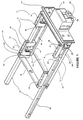
- Figure 1 shows a mounting 11 embodying the invention, for a disk drive unit.
- Figure 1A shows the mounting 11 with a disk drive unit 12 housed therein.
- the disk drive unit 12 has a data storage disk and movable disk head (not shown) supported in a main body 13.
- the mounting 11 comprises a carrier 14, also referred to as a carrier tray, for carrying the disk drive unit 12 during required movement of the disk drive unit.
- the carrier 14 defines a space into which the disk drive unit 12 can be inserted.
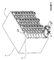
- the carrier 14 is adapted to be inserted with the disk drive unit into a receiving frame 8 shown by way of example in Figure 5 as a tester rack 42.
- the receiving frame 8 of Figure 5 provides a plurality of bays 43 each having a supporting structure 10 ( Figure 1) including a pair of side rails 44, to be described more fully hereinafter.
- the carrier 14 is formed by two side wall portions 16, a front wall 17, a rear wall 18 and a floor 19.
- a retaining assembly 9 for retaining the disk drive unit in the carrier includes four retaining devices 15 positioned with two retaining devices 15 towards the front of the carrier 14, and two retaining devices towards the rear of the carrier 14.
- each retaining device 15 comprises a resilient member 15.
- Each resilient member 15 consists of a spring which acts between the carrier 14 and the disk drive unit 12.
- Each resilient member 15 consists of a clamping spring arranged to grip the disk drive unit 12 by bearing against the disk drive unit and by being resilient biased inwardly against the disk drive unit.
- Each spring 15 is mounted in a sub-frame 22 which forms, with the spring 15, a self contained spring unit 21 which is releasable secured to the side wall portions 16 in such a manner that it can be removed for servicing.
- the sub-frame 22 is secured by a dovetail joint 23 to the main part of the carrier 14, and is additionally screwed thereto by a screw (not shown).
- each clamping spring 15 consists of a sheet 32 of stiff resilient material bent along a bend line 25 (also referred to as a fold line).
- the distal ends of the spring 15 are curled to provide rounded ends 26.
- the curled ends 26 of the clamping spring 15 are intended to bear upon components of a receiving frame (not yet described) into which the carrier 14 is intended to be inserted.
- the ends 26 are rounded so that upon compression of the clamping spring 15, the curled ends 26 are free to slide along a bearing surface as the angle of the bend line 25 increases when the spring is in the compressed condition.
- Figure 2B shows the spring units 21 in plan view from above and shows an end view of the dovetail section 23 at each end of the spring unit.
- Each spring unit is identical, to simplify manufacture.
- each spring unit is secured by one or other of the dovetail sections 23 sliding into a corresponding protruding section 28 provided on the main carrier structure ( Figure 1).
- the sub-frame 22 is secured by a screw (not shown) extending upwardly through the side wall portion 16 into the base of the sub-frame 22.
- the protruding dovetail section 28 extends from the front wall 17.
- the protruding section 28 extends from an end portion 16A of the carrier integral with the side wall portion 16.
- each sub-frame 22 comprises a lower base portion 29 and an upper portion 30, linked to each other by two upright side portions 31 and 32 positioned one at each end of the sub-frame 22.
- the clamping spring 15 has a main portion 33 in which the bend line 25 is formed, and two upright side limbs 34 and 35.
- the sub-frame 22 has an inner surface 27A on the base portion 29 of the sub-frame, and an inner surface on the upper portion 30 of the sub-frame. The purpose of the inner surfaces is to loosely retain the curled ends 26 of the clamping spring 15.
- the spring unit 21 includes a further spring consisting of a positioning spring 37.
- This spring is a fine wire which is located by passing through two apertures 38 in the clamping spring 15.
- the positioning spring 37 is positioned approximately parallel to the base of the carrier and is threaded through the apertures 38 so as to pass on the outer side of the fold line 25 and to be positioned on the inner sides of the curled ends 26, relative to the inside and outside of the carrier 14.
- the positioning spring 37 extends sideways at each end a distance sufficient to extend behind the side portions 31 and 32 of the sub-frame 22, when seen from the exterior of the carrier 14, as shown in the view of Figure 2.
- both the clamping spring 15 and the positioning spring 37 are loosely fitted, relative to each other, and relative to the sub-frame 22.
- the clamping spring 15 In the loosely fitted state, the clamping spring 15 is restrained from escaping from the sub-frame 22 by movement outwardly (relative to the carrier 14) by the curled ends 26 contacting the inner surface 27 of the upper portion 30 of the sub-frame 22.
- the clamping spring 15 is restrained from movement inwardly (relative to the carrier 14) by the positioning spring 37 bearing at its distal ends against the side-portions 31 and 32 of the sub-frame 22.
- the positioning spring 37 bends in a bow shape inwardly towards the inner space of the carrier, and allows the bend line portion 25 to move inwardly into the interior space of the carrier 14.
- the positioning spring 37 exerts an outward bias on the clamping spring 15 and moves it bodily outwardly to withdraw partially from the interior space of the carrier 14.
- the lower edge 40 of the clamping spring 15 is shaped to be inclined upwardly in a direction away from the fold line 25 towards the distal ends 26 of the clamping spring 15.
- the effect of this is that, in the side sectional view of the clamping spring 15 shown in Figure 2A, the lower edge 40 is inclined relative to the fold line 25.
- the clamping spring 15 rests on a horizontal upper surface 41 of the side wall portions 16 of the carrier (shown in Figure 1). Because of the loose fit of the clamping spring 15 in its rest position, the effect of the inclined lower edge 40 is that the clamping spring 15 rests on the upper surface 41 in an inclined position as shown in Figure 2A.
- the lower end of the fold line 25 extends slightly into the interior space of the carrier 14, whereas the upper end of the fold line 25 is in a retracted position within the interior of the sub-frame 22. The reason for this rest position will be explained more fully hereinafter, but is generally in order to facilitate insertion of the disk drive unit 12 into the carrier 14.
- FIG. 5 there is shown a tester rack 42 for housing disk drive units for testing.
- the rack 42 provides a plurality of bays 43 each having side rails 44 (shown in Figure 1) which locate in the space between the upper portion 30 and base portion 29 of each sub-frame 22 of the carrier 14.
- Each rail 44 extends inwardly to an extent of about one third of the thickness of the spring unit 21, that is to say extends inwardly to about the position of the dotted line R-R in Figure 2B.
- the overall sides of the carrier 14 are formed by the side wall portions 16, and the sub-frames 22, but a clear space is left on either side of the carrier 14 in the region between the sub-frames 22.
- the purpose of this clear region is to allow, in an automated system, the disk drive unit 12 to be gripped at the centre of the sides of the main body 13 by a robotic gripping device which can lift and manoeuvre a disk drive unit.
- the disk drive unit may be lowered into the carrier by a vertical movement.
- the carrier 14 is then presented to the tester rack 42, and engaged with the rails 44 as has been described above.
- the carrier 14 is then pushed home into the rack 42, and the clamping springs 15 are moved inwardly by the rails 44, so that the disk drive unit 12 is firmly clamped by the clamping springs 15 being compressed.
- This compression takes place by the bend at the bend line 25 being opened by pressure between the side of the disk drive unit main body 13 and the curled ends 26 bearing against the inner faces of the rails 44.
- the stiffness of the clamping springs 15 is very much greater than that of the positioning spring 37, which plays no part in exerting the clamping force on the disk drive unit.
- a suitable tapered lead-in is provided at each connector, so that any slight misalignment due to tolerances, is taken up by movement of the entire disk drive unit relative to the carrier 14. Because the clamping springs 15 allow a small amount of movement, whilst retaining the required clamping characteristics, the tolerances can be taken up by movement of the entire disk drive unit, rather than by movement of electrical connectors in a floating mounting relative to the tester rack. This allows simplification in the manufacture of the tester rack, with consequent savings in manufacturing costs, and maintenance costs.
- the disk drive unit 12 is located inside the space in the carrier 14, longitudinally by the rear wall 18 and by three projecting ribs 60 which project from the inside of the front portion 17.
- FIGs 2C, 2D and 2E there is shown a modification of the retaining device 15 as shown in Figures 2, 2A and 2B.
- the retaining device 15' consists of a clamping spring 15' generally of the same shape as that shown in Figures 2, 2A and 2B, but with the lower edge 40' perpendicular to the bend line 25' and to the rounded ends 26', rather than being inclined as shown in Figure 2A.
- the positioning of the positioning spring 37', and the dimensions of the various components of the sub-frame 22' are selected to be such that the positioning spring 37' holds the clamping spring 15' in a position towards the surfaces 27' and 27A' of the sub-frame 22', as shown in Figure 2D.
- the clamping spring 15' is held with the bend line 25 not protruding into the space defined by the carrier 14 ( Figure 1).
- each resilient member 15 is movably mounted on the carrier 14 by a floating mounting in which the resilient member is loosely held in the wall of the carrier.
- the resilient member is mounted so as to allow movement of the resilient member 15 as a whole relative to the carrier.
- each resilient members 15 can secure the disk drive unit 12 in the receiving frame 8 by acting directly between the disk drive unit 12 and the receiving frame 8.
- resilient devices have been used to secure a disk drive unit in a receiving frame, either by acting between the wall of the receiving frame and the carrier, or between the carrier and the disk drive unit, or both.
- the arrangement described embodying the present invention is simpler and more effective in securing the disk drive unit.
- the action of sliding the carrier 14 into the receiving frame causes the springs 15 to be compressed by means of the rails 44, which have a taper at the leading edge to facilitate a progressive clamping action.
- the single action of installing the carrier tray containing the disk drive unit into the receiving frame enables the electrical connector (not shown) at the rear of the disk drive unit to align and connect with the corresponding connector in the receiving frame.
- the positioning spring 37 which is a hair spring, retracts the clamping spring 15 when the carrier is out of the frame, to protect the disk drive unit from damage that may be caused if the disk drive unit were to contact the upper surfaces of the clamping springs 15.
- the floating mounting of the springs 15 and the flexibility of the clamping springs 15 enables the disk drive unit to have a degree of lateral movement, to permit the final alignment of the electrical connectors in a lateral direction.
- the provision of lateral movement of the disk drive unit against the clamping springs provides that manufacturing tolerances can be allowed for without the need for a floating electrical connector at the rear of the receiving bay.
- the overall arrangement illustrated has a low space requirement.
- the carrier tray contains all of the clamping mechanism so that it is not necessary to suspend operation of an overall test system to service the clamping mechanism.
- the clamping mechanism can be serviced individually for each carrier.
- retaining devices 15 positioned approximately one at each corner of the carrier 14, numerous other arrangements can be provided in accordance with the invention.
- at least one retaining device 15 is provided on each side of the carrier 14, at least some of the advantages of the invention can be obtained by providing a single retaining device 15 on one side of the carrier 14, with one or more fixed locations on the other side of the carrier 14 projecting from the side walls of the carrier 14 and locating against the side of the disk drive unit.
- the disk drive unit will be located between one or more fixed locations on one side of the carrier 14, and will be located on the other side of the disk drive unit by the single floating retaining device 15 on the other side.
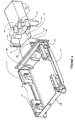
- the front portion 17 of the carrier 14 has a coupling structure 47 projecting outwardly from the front of the carrier 14 and including side portions 48 adapted to be gripped by an automated robotic gripping device 49 for moving the carrier into and out of the tester rack 42.
- the robotic gripping device 49 comprises an arm end 50 extending from a robotic arm (not shown) capable of controlled three dimensional movement, and a pair of gripping claws 51 and 52.
- the claws are movable by a rotary movement about two spaced apart vertical axes 53 and 54 on rotary bearings (not shown) mounted on the arm end 50.
- Each claw 51, 52 has at its distal end a rectangular, tapered, projection part 55 which is of a cross-section and shape such as to co-operate with a corresponding rectangular indentation 56 on the side portion 48 of the coupling structure 47.
- the sides of the indentation 56 are tapered to correspond to the tapered shape of the claw ends 55 so that a tapered lead-in is provided as the claws 51 close to bring the locking projections 55 into mating engagement with the indentations 56.
- the latch 58 has a control lever 59 which is flexible to allow up and down movement relative to the main part of the coupling structure 47.
- the latch (not shown) is released.
- the lever 59 is released to its downward rest position, the latch is engaged.
- the relative positions of the indentations 56, and the claw ends 55, and the finger 57, are such that when the claws 52 and 51 are closed and the claw ends 55 are engaged fully with the indentations 56, the finger 57 raises the lever 59 and releases the latch.
- the purpose of the latch is to lock the carrier 14 into the tester rack, or into any other receiving frame having the rails 44 into which the carrier 14 is inserted.
- the procedure is reversed.
- the arm end 50 is moved towards the coupling structure 47 until the projecting finger 57 has been fully engaged with the lever 59 to release the latch 58.
- the claws 51 and 52 are then closed into the indentations 56, and the arm end 50 is moved backwards, to withdraw the carrier.
- Figure 6 illustrates an earlier stage in the automated process, whereby the disk drive unit 12 can be inserted into and removed from a carrier 14.
- the overall sides of the carrier 14 are formed by the side wall portions 16, and the sub-frames 22, but a clear space is left on either side of the carrier 14 in the region between the sub-frames 22.
- the purpose of this clear region is to allow, in the automatic system, the disk drive unit 12 to be gripped at the centre of the sides of the main body 13 by a robotic gripping device 61 shown in Figure 6 which can lift and manoeuvre a disk drive unit.
- the disk drive unit may be lifted from an entry presentation position by flat side-gripping elements 62 and 63 of the robotic device 61, may be lifted and manoeuvred to a position vertically above a carrier 14, and may then be lowered into the carrier with the side gripping elements 62, 63 of the robotic device 61 having a clearance at each side between the sub-frames 22.
- the side gripping elements 62, 63 are then released and the robotic device 61 removed.
- the carrier 14 is then lifted and manoeuvred, by the further robotic device 49.
- the tester rack 42 is shown merely by way of example of a frame into which the carrier 14 may be inserted.
- the rails 44 may be provided in any other frame which is required, for example in a test apparatus which can accommodate only a single disk drive unit for testing, or alternatively into a frame of equipment to be used by an end user, such as a data storage apparatus comprising a rack of disk drives in computing equipment.
- the rails may be provided in a further component which is itself a carrier and may be moved by a robotic transport device.
- the latch mechanism 58 may be used to lock the carrier 14 in any of these forms of frame.
Landscapes
- Engineering & Computer Science (AREA)
- Theoretical Computer Science (AREA)
- General Physics & Mathematics (AREA)
- Human Computer Interaction (AREA)
- Physics & Mathematics (AREA)
- General Engineering & Computer Science (AREA)
- Power Engineering (AREA)
- Computer Hardware Design (AREA)
- Automatic Disk Changers (AREA)
- Moving Of Heads (AREA)
- Holding Or Fastening Of Disk On Rotational Shaft (AREA)
- Supporting Of Heads In Record-Carrier Devices (AREA)
- Feeding And Guiding Record Carriers (AREA)
- Automobile Manufacture Line, Endless Track Vehicle, Trailer (AREA)
- Warehouses Or Storage Devices (AREA)
Claims (19)
- Monture de lecteur de disque ayant un disque de mémorisation de données, une tête pour disque mobile et un corps principal supportant le disque et la tête pour disque, la monture comportant :un support (14) pour supporter un lecteur de disque (12) pendant un déplacement requis du lecteur de disque, le support (14) définissant un espace dans lequel le lecteur de disque (12) peut être inséré, et le support étant adapté pour être inséré avec le lecteur de disque dans un châssis de réception (8) pour une utilisation opérationnelle, etau moins un dispositif de retenue (15) monté sur le support (14) pour fixer le lecteur de disque (12) dans le châssis de réception (8) lorsque le support est inséré dans le châssis,
caractérisée en ce quele ou chaque dispositif de retenue (15) est monté de manière mobile sur le support (14) pour permettre un déplacement du dispositif sous la forme d'un tout par rapport au support, et le ou chaque dispositif de retenue est agencé pour fixer le lecteur de disque (12) dans le châssis de réception (8) en agissant directement entre le lecteur de disque (12) et le châssis de réception (8). - Monture selon la revendication 1, dans laquelle le ou chaque dispositif de retenue (15) est agencé pour agir entre le lecteur de disque et le châssis de réception en utilisation, par l'effet d'une compression du dispositif de retenue entre le lecteur de disque (12) et le support (14).
- Monture selon la revendication 2, dans laquelle le ou chaque dispositif de retenue (15) est agencé pour être comprimé entre le lecteur de disque (12) et le châssis de réception (8) par l'effet du déplacement du support (14) dans le châssis de réception.
- Monture selon l'une quelconque des revendications précédentes, incluant au moins un dit dispositif de retenue (15) monté sur chaque côté du support (14).
- Monture selon l'une quelconque des revendications précédentes, dans laquelle le ou chaque dispositif de retenue (15) est mobile entre une première position rétractée dans laquelle le dispositif de retenue est rétracté entièrement ou partiellement à l'extérieur dudit espace du support (14), en permettant d'insérer le lecteur de disque (12) dans le support (14), et une seconde position de fonctionnement dans laquelle le dispositif de retenue (15) s'étend dans ledit espace du support et vient en appui contre le lecteur de disque dans une plus grande mesure que dans la première position.
- Monture selon la revendication .5, dans laquelle le ou chaque dispositif de retenue (15) comporte une surface d'actionnement s'étendant vers l'extérieur (26) adaptée pour coopérer avec une partie (44) du châssis de réception (8), de telle manière que lorsque le support (14) est situé dans le châssis (8), la partie du châssis est en appui contre ladite surface d'actionnement et pousse le dispositif de retenue (15) vers l'intérieur pour appuyer contre le lecteur de disque (12) qui est.situé dans le support.
- Monture selon l'une quelconque des revendications précédentes, dans laquelle le ou chaque dispositif de retenue (15) est monté dans une paroi du support (14) et s'étend vers l'intérieur en direction dudit espace du support destiné au lecteur de disque (12) et vers l'extérieur pour venir en prise avec le châssis de réception (8) lorsque le support (14) est inséré dans le châssis de réception (8).
- Monture selon la revendication 7, dans laquelle le ou chaque dispositif de retenue a une partie qui fait saillie vers l'intérieur en direction dudit espace pour le lecteur de disque et qui est inclinée par rapport à une perpendiculaire à un plancher du support, l'inclinaison étant dans un sens tel que l'insertion d'un lecteur de disque dans l'espace amène le lecteur de disque à venir en prise avec la partie inclinée du dispositif de retenue, et à déplacer progressivement le dispositif de retenue vers l'extérieur lorsque le lecteur de disque est inséré dans l'espace.
- Monture selon la revendication 7 ou 8, dans laquelle le dispositif de retenue a une partie qui s'étend vers l'extérieur dans un évidement existant dans le côté du support, lequel évidement est adapté pour coopérer avec un rail de support situé sur le châssis de réception de telle sorte que, lorsque le support est inséré dans le châssis de réception, le rail vient en contact avec une partie en saillie vers l'extérieur du dispositif de retenue, et comprime le dispositif de retenue entre le rail et le lecteur de disque situé dans le support.
- Monture selon l'une quelconque des revendications précédentes, incluant quatre dits dispositifs de retenue (15) positionnés en ayant deux dispositifs de retenue (15) situés vers l'avant du support (14) et deux dispositifs de retenue (15) situés vers l'arrière du support, par rapport à la direction d'insertion du support dans le châssis de réception (8), chaque côté du support (14) ayant une ouverture exposant le côté du lecteur de disque (12) lorsque le lecteur de disque est dans le support, l'ouverture étant conformée pour permettre de déposer le lecteur de disque dans le support ou le lever à partir de celui-ci en saisissant les côtés exposés du lecteur de disque.
- Monture selon l'une quelconque des revendications précédentes, dans laquelle le support a une structure d'accouplement (47) faisant saillie vers l'extérieur à partir de l'avant du support, adaptée pour être saisie par un dispositif robotique (49) pour déplacer le support dans le châssis et à l'extérieur de celui-ci.
- Monture selon l'une quelconque des revendications précédentes, en combinaison avec un châssis de réception (8) dans lequel le support peut être inséré avec un lecteur de disque (12) pour utilisation opérationnelle du lecteur de disque.
- Monture selon la revendication 12, dans laquelle le châssis de réception (8) comporte un bâti de testeur (42) adapté pour recevoir plusieurs supports ayant des lecteurs de disque respectifs pour tester les lecteurs de disque.
- Monture selon la revendication 12, dans laquelle le châssis de réception (8) comporte un ensemble de mémorisation de données adapté pour recevoir une pluralité de supports (14) ayant des lecteurs de disque respectifs (12) pour une utilisation opérationnelle des lecteurs de disque pour mémorisation de données.
- Monture selon la revendication 12, dans laquelle le châssis de réception (8) comporte un châssis d'un ordinateur adapté pour recevoir un support unique (14) avec son lecteur de disque associé pour traitement de données.
- Monture selon l'une quelconque des revendications précédentes, dans laquelle chaque dispositif de retenue (15) comporte un élément élastique (15).
- Monture selon la revendication 16, dans laquelle chaque élément élastique (15) est formé d'une feuille de matériau élastique.
- Monture selon la revendication 17, dans laquelle la feuille de matériau élastique a au moins une ligne d'incurvation (25) autour de laquelle la feuille est incurvée pour fournir deux parties de la feuille inclinées l'une par rapport à l'autre selon un angle obtus, l'élasticité de l'élément élastique étant fournie par une compression de l'élément élastique en ouvrant l'angle obtus.
- Monture selon la revendication 18, dans laquelle l'élément élastique (15) est positionné de manière à agir contre un côté extérieur du lecteur de disque lorsqu'il est inséré dans le support, ladite ligne ou lesdites lignes d'incurvation (25) étant agencées dans un plan ou des plans sensiblement parallèles au côté extérieur du lecteur de disque lorsqu'il est inséré dans le support.
Applications Claiming Priority (3)
| Application Number | Priority Date | Filing Date | Title |
|---|---|---|---|
| US31535001P | 2001-08-29 | 2001-08-29 | |
| PCT/GB2002/003871 WO2003021597A1 (fr) | 2001-08-29 | 2002-08-22 | Structure de montage de lecteur de disque et procede de manipulation |
| US315350P | 2010-03-18 |
Publications (2)
| Publication Number | Publication Date |
|---|---|
| EP1421587A1 EP1421587A1 (fr) | 2004-05-26 |
| EP1421587B1 true EP1421587B1 (fr) | 2006-02-22 |
Family
ID=23223998
Family Applications (2)
| Application Number | Title | Priority Date | Filing Date |
|---|---|---|---|
| EP02753149A Expired - Lifetime EP1421587B1 (fr) | 2001-08-29 | 2002-08-22 | Structure de montage de lecteur de disque et procede de manipulation |
| EP02751450A Expired - Lifetime EP1428217B1 (fr) | 2001-08-29 | 2002-08-22 | Assemblage d'unite de lecteur de disque et procede de manipulation |
Family Applications After (1)
| Application Number | Title | Priority Date | Filing Date |
|---|---|---|---|
| EP02751450A Expired - Lifetime EP1428217B1 (fr) | 2001-08-29 | 2002-08-22 | Assemblage d'unite de lecteur de disque et procede de manipulation |
Country Status (7)
| Country | Link |
|---|---|
| US (1) | US7088541B2 (fr) |
| EP (2) | EP1421587B1 (fr) |
| CN (2) | CN100423125C (fr) |
| AT (2) | ATE318443T1 (fr) |
| DE (2) | DE60215680T2 (fr) |
| MY (2) | MY127281A (fr) |
| WO (2) | WO2003021597A1 (fr) |
Families Citing this family (56)
| Publication number | Priority date | Publication date | Assignee | Title |
|---|---|---|---|---|
| US7826975B2 (en) | 2002-07-10 | 2010-11-02 | The Penn State Research Foundation | Method for redesign of microbial production systems |
| US7729112B2 (en) | 2003-09-08 | 2010-06-01 | Xyratex Technology Limited | Mounting for disk drive unit, retaining device and method of loading a disk drive unit |
| KR20070062521A (ko) | 2004-09-17 | 2007-06-15 | 지라텍스 테크놀로지 리미티드 | 디스크 드라이브를 위한 하우징 및 장치 |
| CN100354791C (zh) * | 2004-12-23 | 2007-12-12 | 研华股份有限公司 | 电脑外设设备的多方向固定结构 |
| KR20070121699A (ko) * | 2005-03-23 | 2007-12-27 | 지라텍스 테크놀로지 리미티드 | 디스크 드라이브 지지용 장치 및 디스크 드라이브 테스트장치 |
| WO2006115465A1 (fr) * | 2005-04-26 | 2006-11-02 | Innovative Polymers Pte. Ltd. | Support d'essai pour dispositifs de stockage |
| US8755177B2 (en) * | 2005-09-16 | 2014-06-17 | Xyratex Technology Limited | Method and apparatus for controlling the temperature of a disk drive during manufacture |
| US7483269B1 (en) | 2005-09-30 | 2009-01-27 | Maxtor Corporation | Test rack adapter for hard disk drive |
| JP2008027478A (ja) * | 2006-07-18 | 2008-02-07 | Hitachi Global Storage Technologies Netherlands Bv | 磁気ディスク装置 |
| DE102007011714B4 (de) * | 2007-03-09 | 2009-01-08 | Fujitsu Siemens Computers Gmbh | Speichereinschubkomponente für ein Serverrack |
| CN101169961B (zh) * | 2007-11-30 | 2010-09-15 | 江苏大学 | 光盘组驱动器 |
| US8549912B2 (en) | 2007-12-18 | 2013-10-08 | Teradyne, Inc. | Disk drive transport, clamping and testing |
| US7996174B2 (en) | 2007-12-18 | 2011-08-09 | Teradyne, Inc. | Disk drive testing |
| US7945424B2 (en) * | 2008-04-17 | 2011-05-17 | Teradyne, Inc. | Disk drive emulator and method of use thereof |
| US8102173B2 (en) | 2008-04-17 | 2012-01-24 | Teradyne, Inc. | Thermal control system for test slot of test rack for disk drive testing system with thermoelectric device and a cooling conduit |
| US8095234B2 (en) * | 2008-04-17 | 2012-01-10 | Teradyne, Inc. | Transferring disk drives within disk drive testing systems |
| US8117480B2 (en) | 2008-04-17 | 2012-02-14 | Teradyne, Inc. | Dependent temperature control within disk drive testing systems |
| US7848106B2 (en) | 2008-04-17 | 2010-12-07 | Teradyne, Inc. | Temperature control within disk drive testing systems |
| US8160739B2 (en) | 2008-04-17 | 2012-04-17 | Teradyne, Inc. | Transferring storage devices within storage device testing systems |
| US8305751B2 (en) | 2008-04-17 | 2012-11-06 | Teradyne, Inc. | Vibration isolation within disk drive testing systems |
| US8041449B2 (en) | 2008-04-17 | 2011-10-18 | Teradyne, Inc. | Bulk feeding disk drives to disk drive testing systems |
| US20090262455A1 (en) | 2008-04-17 | 2009-10-22 | Teradyne, Inc. | Temperature Control Within Disk Drive Testing Systems |
| US8238099B2 (en) | 2008-04-17 | 2012-08-07 | Teradyne, Inc. | Enclosed operating area for disk drive testing systems |
| JP2011524060A (ja) | 2008-06-03 | 2011-08-25 | テラダイン、 インコーポレイテッド | 記憶デバイスを処理する方法 |
| JP5242774B2 (ja) * | 2009-04-17 | 2013-07-24 | テラダイン、 インコーポレイテッド | 格納装置搬送、クランピングおよびテスト |
| CN102460580A (zh) * | 2009-06-05 | 2012-05-16 | 齐拉泰克斯技术有限公司 | 用于支撑磁盘驱动器的设备和磁盘驱动器测试设备 |
| KR20120027050A (ko) | 2009-06-05 | 2012-03-20 | 지라텍스 테크놀로지 리미티드 | 디스크 드라이브 지지장치, 디스크 드라이브 테스트 장치 및 디스크 드라이브 테스트 방법 |
| US8628239B2 (en) | 2009-07-15 | 2014-01-14 | Teradyne, Inc. | Storage device temperature sensing |
| US8116079B2 (en) * | 2009-07-15 | 2012-02-14 | Teradyne, Inc. | Storage device testing system cooling |
| US7995349B2 (en) | 2009-07-15 | 2011-08-09 | Teradyne, Inc. | Storage device temperature sensing |
| US8466699B2 (en) | 2009-07-15 | 2013-06-18 | Teradyne, Inc. | Heating storage devices in a testing system |
| US8547123B2 (en) | 2009-07-15 | 2013-10-01 | Teradyne, Inc. | Storage device testing system with a conductive heating assembly |
| US8687356B2 (en) | 2010-02-02 | 2014-04-01 | Teradyne, Inc. | Storage device testing system cooling |
| US7920380B2 (en) | 2009-07-15 | 2011-04-05 | Teradyne, Inc. | Test slot cooling system for a storage device testing system |
| US8270118B1 (en) | 2009-10-30 | 2012-09-18 | Western Digital Technologies, Inc. | Head stack assembly cartridge |
| US8218256B1 (en) | 2009-10-30 | 2012-07-10 | Western Digital Technologies, Inc. | Disk spindle assembly cartridge |
| US9779780B2 (en) | 2010-06-17 | 2017-10-03 | Teradyne, Inc. | Damping vibrations within storage device testing systems |
| US8432630B1 (en) | 2010-06-30 | 2013-04-30 | Western Digital Technologies, Inc. | Disk drive component test system |
| US8687349B2 (en) | 2010-07-21 | 2014-04-01 | Teradyne, Inc. | Bulk transfer of storage devices using manual loading |
| JP2012033240A (ja) * | 2010-07-30 | 2012-02-16 | Fujitsu Ltd | 電子機器及びその製造方法 |
| US9001456B2 (en) | 2010-08-31 | 2015-04-07 | Teradyne, Inc. | Engaging test slots |
| US9459312B2 (en) | 2013-04-10 | 2016-10-04 | Teradyne, Inc. | Electronic assembly test system |
| JP6115443B2 (ja) * | 2013-10-23 | 2017-04-19 | 富士通株式会社 | 物品抜去治具及び物品収容体 |
| US10725091B2 (en) | 2017-08-28 | 2020-07-28 | Teradyne, Inc. | Automated test system having multiple stages |
| US10948534B2 (en) | 2017-08-28 | 2021-03-16 | Teradyne, Inc. | Automated test system employing robotics |
| US10845410B2 (en) | 2017-08-28 | 2020-11-24 | Teradyne, Inc. | Automated test system having orthogonal robots |
| US11226390B2 (en) | 2017-08-28 | 2022-01-18 | Teradyne, Inc. | Calibration process for an automated test system |
| US10983145B2 (en) | 2018-04-24 | 2021-04-20 | Teradyne, Inc. | System for testing devices inside of carriers |
| US10775408B2 (en) | 2018-08-20 | 2020-09-15 | Teradyne, Inc. | System for testing devices inside of carriers |
| US11899042B2 (en) | 2020-10-22 | 2024-02-13 | Teradyne, Inc. | Automated test system |
| US11867749B2 (en) | 2020-10-22 | 2024-01-09 | Teradyne, Inc. | Vision system for an automated test system |
| US11953519B2 (en) | 2020-10-22 | 2024-04-09 | Teradyne, Inc. | Modular automated test system |
| US11754622B2 (en) | 2020-10-22 | 2023-09-12 | Teradyne, Inc. | Thermal control system for an automated test system |
| US11754596B2 (en) | 2020-10-22 | 2023-09-12 | Teradyne, Inc. | Test site configuration in an automated test system |
| CN115072349B (zh) * | 2021-03-12 | 2023-12-22 | 平湖莱顿光学仪器制造有限公司 | 一种用于接放玻片盘的设备、装置以及推紧装置 |
| US12007411B2 (en) | 2021-06-22 | 2024-06-11 | Teradyne, Inc. | Test socket having an automated lid |
Family Cites Families (22)
| Publication number | Priority date | Publication date | Assignee | Title |
|---|---|---|---|---|
| US4754397A (en) | 1985-02-15 | 1988-06-28 | Tandem Computers Incorporated | Fault tolerant modular subsystems for computers |
| JPH04171326A (ja) | 1990-10-31 | 1992-06-18 | Toshiba Corp | 制振板ばね |
| JPH05189861A (ja) | 1991-06-13 | 1993-07-30 | Ricoh Co Ltd | ディスクライブラリー装置,ディスクドライブ装置及びカートリッジ |
| US5463527A (en) * | 1993-10-06 | 1995-10-31 | Allen-Bradley Company, Inc. | Suspension system for disk drives utilizing shear loaded elastomeric supports of different durometer hardnesses and elastomeric pads |
| EP0757351B1 (fr) * | 1995-07-31 | 2001-08-16 | Hewlett-Packard Company, A Delaware Corporation | Structure d'encadrement d'ordinateur avec boítiers modulaires |
| GB9515982D0 (en) | 1995-08-04 | 1995-10-04 | Havant International Ltd | Disk file mounting |
| US5851143A (en) * | 1996-05-10 | 1998-12-22 | Thermal Industries | Disk drive test chamber |
| US5734557A (en) * | 1996-09-13 | 1998-03-31 | Deli U.S.A., L.P. | Mounting assembly for electronic equipment |
| KR100433510B1 (ko) * | 1996-10-28 | 2004-07-16 | 삼성전자주식회사 | 보조 기억장치 고정수단을 갖는 컴퓨터 |
| US5917676A (en) * | 1997-04-30 | 1999-06-29 | Seagate Technology, Inc. | Disc drive vibration reduction device |
| DE29713122U1 (de) * | 1997-07-23 | 1997-10-09 | Chenbro Micom Co. Ltd., Chung Ho, Taipeh | Modulare Befestigung für ein Laufwerk |
| US5970030A (en) * | 1997-12-02 | 1999-10-19 | International Business Machines Corporation | Automated data storage library component exchange using media accessor |
| US6166901A (en) * | 1998-03-13 | 2000-12-26 | International Business Machines Corporation | Vibration dampening system for removable hard disk drive carriers |
| US6209842B1 (en) * | 1998-05-27 | 2001-04-03 | International Business Machines Corporation | Laminated damping device for a carrier |
| GB2342759A (en) | 1998-10-10 | 2000-04-19 | Pti Limited | Data cartridge assembly with vibration damping |
| US6097604A (en) * | 1998-12-23 | 2000-08-01 | Hewlett-Packard Company | Carrier to facilitate installation of an electronic device into an enclosure |
| GB9928211D0 (en) | 1999-11-29 | 2000-01-26 | Havant International Ltd | Disk drive kit |
| US6537013B2 (en) * | 2001-04-26 | 2003-03-25 | International Business Machines Corporation | Picking mechanism with ventilation system for automated library of memory storage units |
| US6464509B1 (en) * | 2001-04-26 | 2002-10-15 | International Business Machines Corporation | System and method requiring zero insertion force and positive retention of removable storage media in a data storage subsystem |
| US6941260B2 (en) * | 2001-04-26 | 2005-09-06 | International Business Machines Corporation | Method and apparatus for emulating a fiber channel port |
| US6754768B2 (en) * | 2001-04-26 | 2004-06-22 | International Business Machines Corporation | Library of hard disk drives with transparent emulating interface |
| US6650601B1 (en) * | 2001-04-26 | 2003-11-18 | International Business Machines Corporation | Hard disk drive picking device and method |
-
2002
- 2002-08-22 EP EP02753149A patent/EP1421587B1/fr not_active Expired - Lifetime
- 2002-08-22 DE DE60215680T patent/DE60215680T2/de not_active Expired - Fee Related
- 2002-08-22 CN CNB028192621A patent/CN100423125C/zh not_active Expired - Fee Related
- 2002-08-22 CN CNB02819263XA patent/CN100505079C/zh not_active Expired - Fee Related
- 2002-08-22 EP EP02751450A patent/EP1428217B1/fr not_active Expired - Lifetime
- 2002-08-22 WO PCT/GB2002/003871 patent/WO2003021597A1/fr not_active Ceased
- 2002-08-22 AT AT02753149T patent/ATE318443T1/de not_active IP Right Cessation
- 2002-08-22 AT AT02751450T patent/ATE343840T1/de not_active IP Right Cessation
- 2002-08-22 US US10/487,403 patent/US7088541B2/en not_active Expired - Fee Related
- 2002-08-22 DE DE60209357T patent/DE60209357T2/de not_active Expired - Fee Related
- 2002-08-22 WO PCT/GB2002/003880 patent/WO2003021598A1/fr not_active Ceased
- 2002-08-28 MY MYPI20023206A patent/MY127281A/en unknown
- 2002-08-28 MY MYPI20023205A patent/MY129822A/en unknown
Also Published As
| Publication number | Publication date |
|---|---|
| HK1063238A1 (en) | 2004-12-17 |
| EP1428217A1 (fr) | 2004-06-16 |
| ATE343840T1 (de) | 2006-11-15 |
| WO2003021598A1 (fr) | 2003-03-13 |
| DE60209357T2 (de) | 2006-11-30 |
| HK1063239A1 (en) | 2004-12-17 |
| EP1421587A1 (fr) | 2004-05-26 |
| MY127281A (en) | 2006-11-30 |
| DE60209357D1 (de) | 2006-04-27 |
| CN100505079C (zh) | 2009-06-24 |
| ATE318443T1 (de) | 2006-03-15 |
| MY129822A (en) | 2007-05-31 |
| CN100423125C (zh) | 2008-10-01 |
| WO2003021597A1 (fr) | 2003-03-13 |
| EP1428217B1 (fr) | 2006-10-25 |
| US20050007691A1 (en) | 2005-01-13 |
| DE60215680T2 (de) | 2007-08-23 |
| US7088541B2 (en) | 2006-08-08 |
| CN1561520A (zh) | 2005-01-05 |
| CN1561521A (zh) | 2005-01-05 |
| DE60215680D1 (de) | 2006-12-07 |
Similar Documents
| Publication | Publication Date | Title |
|---|---|---|
| US7054150B2 (en) | Mounting for disk drive unit and method of handling | |
| US7088541B2 (en) | Mounting for disk drive unit and method of handling | |
| US7729112B2 (en) | Mounting for disk drive unit, retaining device and method of loading a disk drive unit | |
| US6008984A (en) | Disk file mounting | |
| CN100382148C (zh) | 盘驱动器支撑组件、夹持组件及盘驱动器承载器 | |
| JP2771961B2 (ja) | システム構成要素の接続構造 | |
| US4896777A (en) | Lock and shock mounted device for computer disk drive | |
| EP0967615B1 (fr) | Dispositif de support antichoc pour modules de stockage de données | |
| US5652697A (en) | Computer system backplane having ground tabs for interconnecting the backplane ground to the computer system chassis | |
| JPH03152612A (ja) | コンピユータ格納装置 | |
| US5717665A (en) | Locking devices for use in a cartridge handling system | |
| US5540542A (en) | HDA headload carriage tooling | |
| HK1063238B (en) | Mounting for disk drive unit and method of handling | |
| HK1063239B (en) | Mounting for disk drive unit and method of handling | |
| US7487582B2 (en) | Shipping comb for assembling a disk drive | |
| KR20120027472A (ko) | 디스크 드라이브 지지장치 및 디스크 드라이브 테스트 장치 | |
| JP3297186B2 (ja) | ディスクチェンジャのマガジン位置決め機構 | |
| JP2995997B2 (ja) | ディスク装置 | |
| HK1094734A (en) | Disk drive support assembly, clamp assembly and disk drive carrier |
Legal Events
| Date | Code | Title | Description |
|---|---|---|---|
| PUAI | Public reference made under article 153(3) epc to a published international application that has entered the european phase |
Free format text: ORIGINAL CODE: 0009012 |
|
| 17P | Request for examination filed |
Effective date: 20040319 |
|
| AK | Designated contracting states |
Kind code of ref document: A1 Designated state(s): AT BE BG CH CY CZ DE DK EE ES FI FR GB GR IE IT LI LU MC NL PT SE SK TR |
|
| REG | Reference to a national code |
Ref country code: HK Ref legal event code: DE Ref document number: 1063238 Country of ref document: HK |
|
| GRAP | Despatch of communication of intention to grant a patent |
Free format text: ORIGINAL CODE: EPIDOSNIGR1 |
|
| GRAS | Grant fee paid |
Free format text: ORIGINAL CODE: EPIDOSNIGR3 |
|
| GRAA | (expected) grant |
Free format text: ORIGINAL CODE: 0009210 |
|
| AK | Designated contracting states |
Kind code of ref document: B1 Designated state(s): AT BE BG CH CY CZ DE DK EE ES FI FR GB GR IE IT LI LU MC NL PT SE SK TR |
|
| PG25 | Lapsed in a contracting state [announced via postgrant information from national office to epo] |
Ref country code: AT Free format text: LAPSE BECAUSE OF FAILURE TO SUBMIT A TRANSLATION OF THE DESCRIPTION OR TO PAY THE FEE WITHIN THE PRESCRIBED TIME-LIMIT Effective date: 20060222 Ref country code: SK Free format text: LAPSE BECAUSE OF FAILURE TO SUBMIT A TRANSLATION OF THE DESCRIPTION OR TO PAY THE FEE WITHIN THE PRESCRIBED TIME-LIMIT Effective date: 20060222 Ref country code: NL Free format text: LAPSE BECAUSE OF FAILURE TO SUBMIT A TRANSLATION OF THE DESCRIPTION OR TO PAY THE FEE WITHIN THE PRESCRIBED TIME-LIMIT Effective date: 20060222 Ref country code: LI Free format text: LAPSE BECAUSE OF FAILURE TO SUBMIT A TRANSLATION OF THE DESCRIPTION OR TO PAY THE FEE WITHIN THE PRESCRIBED TIME-LIMIT Effective date: 20060222 Ref country code: FI Free format text: LAPSE BECAUSE OF FAILURE TO SUBMIT A TRANSLATION OF THE DESCRIPTION OR TO PAY THE FEE WITHIN THE PRESCRIBED TIME-LIMIT Effective date: 20060222 Ref country code: CH Free format text: LAPSE BECAUSE OF FAILURE TO SUBMIT A TRANSLATION OF THE DESCRIPTION OR TO PAY THE FEE WITHIN THE PRESCRIBED TIME-LIMIT Effective date: 20060222 Ref country code: BE Free format text: LAPSE BECAUSE OF FAILURE TO SUBMIT A TRANSLATION OF THE DESCRIPTION OR TO PAY THE FEE WITHIN THE PRESCRIBED TIME-LIMIT Effective date: 20060222 Ref country code: IT Free format text: LAPSE BECAUSE OF FAILURE TO SUBMIT A TRANSLATION OF THE DESCRIPTION OR TO PAY THE FEE WITHIN THE PRESCRIBED TIME-LIMIT;WARNING: LAPSES OF ITALIAN PATENTS WITH EFFECTIVE DATE BEFORE 2007 MAY HAVE OCCURRED AT ANY TIME BEFORE 2007. THE CORRECT EFFECTIVE DATE MAY BE DIFFERENT FROM THE ONE RECORDED. Effective date: 20060222 |
|
| REG | Reference to a national code |
Ref country code: GB Ref legal event code: FG4D |
|
| REG | Reference to a national code |
Ref country code: CH Ref legal event code: EP |
|
| REG | Reference to a national code |
Ref country code: IE Ref legal event code: FG4D |
|
| REF | Corresponds to: |
Ref document number: 60209357 Country of ref document: DE Date of ref document: 20060427 Kind code of ref document: P |
|
| REG | Reference to a national code |
Ref country code: HK Ref legal event code: GR Ref document number: 1063238 Country of ref document: HK |
|
| PG25 | Lapsed in a contracting state [announced via postgrant information from national office to epo] |
Ref country code: DK Free format text: LAPSE BECAUSE OF FAILURE TO SUBMIT A TRANSLATION OF THE DESCRIPTION OR TO PAY THE FEE WITHIN THE PRESCRIBED TIME-LIMIT Effective date: 20060522 Ref country code: BG Free format text: LAPSE BECAUSE OF FAILURE TO SUBMIT A TRANSLATION OF THE DESCRIPTION OR TO PAY THE FEE WITHIN THE PRESCRIBED TIME-LIMIT Effective date: 20060522 Ref country code: SE Free format text: LAPSE BECAUSE OF FAILURE TO SUBMIT A TRANSLATION OF THE DESCRIPTION OR TO PAY THE FEE WITHIN THE PRESCRIBED TIME-LIMIT Effective date: 20060522 |
|
| PG25 | Lapsed in a contracting state [announced via postgrant information from national office to epo] |
Ref country code: ES Free format text: LAPSE BECAUSE OF FAILURE TO SUBMIT A TRANSLATION OF THE DESCRIPTION OR TO PAY THE FEE WITHIN THE PRESCRIBED TIME-LIMIT Effective date: 20060602 |
|
| PG25 | Lapsed in a contracting state [announced via postgrant information from national office to epo] |
Ref country code: PT Free format text: LAPSE BECAUSE OF FAILURE TO SUBMIT A TRANSLATION OF THE DESCRIPTION OR TO PAY THE FEE WITHIN THE PRESCRIBED TIME-LIMIT Effective date: 20060724 |
|
| NLV1 | Nl: lapsed or annulled due to failure to fulfill the requirements of art. 29p and 29m of the patents act | ||
| PG25 | Lapsed in a contracting state [announced via postgrant information from national office to epo] |
Ref country code: MC Free format text: LAPSE BECAUSE OF NON-PAYMENT OF DUE FEES Effective date: 20060831 |
|
| REG | Reference to a national code |
Ref country code: CH Ref legal event code: PL |
|
| PLBE | No opposition filed within time limit |
Free format text: ORIGINAL CODE: 0009261 |
|
| STAA | Information on the status of an ep patent application or granted ep patent |
Free format text: STATUS: NO OPPOSITION FILED WITHIN TIME LIMIT |
|
| 26N | No opposition filed |
Effective date: 20061123 |
|
| EN | Fr: translation not filed | ||
| PGFP | Annual fee paid to national office [announced via postgrant information from national office to epo] |
Ref country code: IE Payment date: 20070808 Year of fee payment: 6 |
|
| PGFP | Annual fee paid to national office [announced via postgrant information from national office to epo] |
Ref country code: DE Payment date: 20070829 Year of fee payment: 6 |
|
| PG25 | Lapsed in a contracting state [announced via postgrant information from national office to epo] |
Ref country code: FR Free format text: LAPSE BECAUSE OF FAILURE TO SUBMIT A TRANSLATION OF THE DESCRIPTION OR TO PAY THE FEE WITHIN THE PRESCRIBED TIME-LIMIT Effective date: 20070420 Ref country code: CZ Free format text: LAPSE BECAUSE OF FAILURE TO SUBMIT A TRANSLATION OF THE DESCRIPTION OR TO PAY THE FEE WITHIN THE PRESCRIBED TIME-LIMIT Effective date: 20060222 Ref country code: GR Free format text: LAPSE BECAUSE OF FAILURE TO SUBMIT A TRANSLATION OF THE DESCRIPTION OR TO PAY THE FEE WITHIN THE PRESCRIBED TIME-LIMIT Effective date: 20060523 |
|
| PG25 | Lapsed in a contracting state [announced via postgrant information from national office to epo] |
Ref country code: EE Free format text: LAPSE BECAUSE OF FAILURE TO SUBMIT A TRANSLATION OF THE DESCRIPTION OR TO PAY THE FEE WITHIN THE PRESCRIBED TIME-LIMIT Effective date: 20060222 |
|
| PG25 | Lapsed in a contracting state [announced via postgrant information from national office to epo] |
Ref country code: LU Free format text: LAPSE BECAUSE OF NON-PAYMENT OF DUE FEES Effective date: 20060822 Ref country code: TR Free format text: LAPSE BECAUSE OF FAILURE TO SUBMIT A TRANSLATION OF THE DESCRIPTION OR TO PAY THE FEE WITHIN THE PRESCRIBED TIME-LIMIT Effective date: 20060222 |
|
| PG25 | Lapsed in a contracting state [announced via postgrant information from national office to epo] |
Ref country code: CY Free format text: LAPSE BECAUSE OF FAILURE TO SUBMIT A TRANSLATION OF THE DESCRIPTION OR TO PAY THE FEE WITHIN THE PRESCRIBED TIME-LIMIT Effective date: 20060222 Ref country code: FR Free format text: LAPSE BECAUSE OF FAILURE TO SUBMIT A TRANSLATION OF THE DESCRIPTION OR TO PAY THE FEE WITHIN THE PRESCRIBED TIME-LIMIT Effective date: 20060222 |
|
| PG25 | Lapsed in a contracting state [announced via postgrant information from national office to epo] |
Ref country code: IE Free format text: LAPSE BECAUSE OF NON-PAYMENT OF DUE FEES Effective date: 20080822 |
|
| PG25 | Lapsed in a contracting state [announced via postgrant information from national office to epo] |
Ref country code: DE Free format text: LAPSE BECAUSE OF NON-PAYMENT OF DUE FEES Effective date: 20090303 |
|
| PGFP | Annual fee paid to national office [announced via postgrant information from national office to epo] |
Ref country code: GB Payment date: 20140721 Year of fee payment: 13 |
|
| GBPC | Gb: european patent ceased through non-payment of renewal fee |
Effective date: 20150822 |
|
| PG25 | Lapsed in a contracting state [announced via postgrant information from national office to epo] |
Ref country code: GB Free format text: LAPSE BECAUSE OF NON-PAYMENT OF DUE FEES Effective date: 20150822 |