EP1421592B1 - Neue herstellungsverfahren einer spule - Google Patents
Neue herstellungsverfahren einer spule Download PDFInfo
- Publication number
- EP1421592B1 EP1421592B1 EP02755238A EP02755238A EP1421592B1 EP 1421592 B1 EP1421592 B1 EP 1421592B1 EP 02755238 A EP02755238 A EP 02755238A EP 02755238 A EP02755238 A EP 02755238A EP 1421592 B1 EP1421592 B1 EP 1421592B1
- Authority
- EP
- European Patent Office
- Prior art keywords
- layer
- former
- coil
- buffer layer
- layers
- Prior art date
- Legal status (The legal status is an assumption and is not a legal conclusion. Google has not performed a legal analysis and makes no representation as to the accuracy of the status listed.)
- Expired - Lifetime
Links
- 238000004519 manufacturing process Methods 0.000 title claims abstract description 32
- 238000004804 winding Methods 0.000 claims abstract description 127
- 238000000151 deposition Methods 0.000 claims abstract description 92
- 239000000463 material Substances 0.000 claims abstract description 45
- 238000011065 in-situ storage Methods 0.000 claims abstract description 14
- 238000007493 shaping process Methods 0.000 claims abstract description 7
- 238000000034 method Methods 0.000 claims description 114
- 230000008021 deposition Effects 0.000 claims description 57
- 229910021521 yttrium barium copper oxide Inorganic materials 0.000 claims description 55
- 230000008569 process Effects 0.000 claims description 46
- 238000005137 deposition process Methods 0.000 claims description 11
- 238000007735 ion beam assisted deposition Methods 0.000 claims description 10
- 238000010884 ion-beam technique Methods 0.000 claims description 10
- 230000002787 reinforcement Effects 0.000 claims description 10
- 239000002826 coolant Substances 0.000 claims description 4
- 238000012546 transfer Methods 0.000 claims description 4
- 230000000873 masking effect Effects 0.000 claims description 3
- 238000012360 testing method Methods 0.000 claims description 3
- 238000003754 machining Methods 0.000 claims description 2
- 239000010408 film Substances 0.000 description 66
- 239000000758 substrate Substances 0.000 description 28
- 238000010438 heat treatment Methods 0.000 description 19
- 239000004020 conductor Substances 0.000 description 14
- 238000013459 approach Methods 0.000 description 13
- QVGXLLKOCUKJST-UHFFFAOYSA-N atomic oxygen Chemical compound [O] QVGXLLKOCUKJST-UHFFFAOYSA-N 0.000 description 10
- 230000000694 effects Effects 0.000 description 10
- 229910052760 oxygen Inorganic materials 0.000 description 10
- 239000001301 oxygen Substances 0.000 description 10
- 239000010409 thin film Substances 0.000 description 8
- 238000005096 rolling process Methods 0.000 description 7
- 238000000869 ion-assisted deposition Methods 0.000 description 5
- 238000012986 modification Methods 0.000 description 5
- 230000004048 modification Effects 0.000 description 5
- 238000011282 treatment Methods 0.000 description 5
- IJGRMHOSHXDMSA-UHFFFAOYSA-N Atomic nitrogen Chemical compound N#N IJGRMHOSHXDMSA-UHFFFAOYSA-N 0.000 description 4
- PXHVJJICTQNCMI-UHFFFAOYSA-N Nickel Chemical compound [Ni] PXHVJJICTQNCMI-UHFFFAOYSA-N 0.000 description 4
- 230000015572 biosynthetic process Effects 0.000 description 4
- 229910000420 cerium oxide Inorganic materials 0.000 description 4
- 238000000576 coating method Methods 0.000 description 4
- 238000010276 construction Methods 0.000 description 4
- 239000013078 crystal Substances 0.000 description 4
- 238000005516 engineering process Methods 0.000 description 4
- 238000001704 evaporation Methods 0.000 description 4
- 230000008020 evaporation Effects 0.000 description 4
- BMMGVYCKOGBVEV-UHFFFAOYSA-N oxo(oxoceriooxy)cerium Chemical compound [Ce]=O.O=[Ce]=O BMMGVYCKOGBVEV-UHFFFAOYSA-N 0.000 description 4
- 235000012771 pancakes Nutrition 0.000 description 4
- 238000007736 thin film deposition technique Methods 0.000 description 4
- 229910000990 Ni alloy Inorganic materials 0.000 description 3
- KDLHZDBZIXYQEI-UHFFFAOYSA-N Palladium Chemical compound [Pd] KDLHZDBZIXYQEI-UHFFFAOYSA-N 0.000 description 3
- 239000011248 coating agent Substances 0.000 description 3
- 238000012937 correction Methods 0.000 description 3
- 230000006378 damage Effects 0.000 description 3
- 238000003618 dip coating Methods 0.000 description 3
- 238000005530 etching Methods 0.000 description 3
- 238000001125 extrusion Methods 0.000 description 3
- 230000001939 inductive effect Effects 0.000 description 3
- 239000007788 liquid Substances 0.000 description 3
- 238000002595 magnetic resonance imaging Methods 0.000 description 3
- 230000005855 radiation Effects 0.000 description 3
- 229910052761 rare earth metal Inorganic materials 0.000 description 3
- 238000011160 research Methods 0.000 description 3
- 238000004544 sputter deposition Methods 0.000 description 3
- 239000000126 substance Substances 0.000 description 3
- 239000002887 superconductor Substances 0.000 description 3
- 238000002207 thermal evaporation Methods 0.000 description 3
- 238000005481 NMR spectroscopy Methods 0.000 description 2
- 238000002441 X-ray diffraction Methods 0.000 description 2
- MCMNRKCIXSYSNV-UHFFFAOYSA-N Zirconium dioxide Chemical compound O=[Zr]=O MCMNRKCIXSYSNV-UHFFFAOYSA-N 0.000 description 2
- 230000004888 barrier function Effects 0.000 description 2
- 230000008901 benefit Effects 0.000 description 2
- 238000001816 cooling Methods 0.000 description 2
- 238000005520 cutting process Methods 0.000 description 2
- 230000007547 defect Effects 0.000 description 2
- 239000003814 drug Substances 0.000 description 2
- 238000010894 electron beam technology Methods 0.000 description 2
- 230000004907 flux Effects 0.000 description 2
- 238000009413 insulation Methods 0.000 description 2
- 229910052751 metal Inorganic materials 0.000 description 2
- 239000002184 metal Substances 0.000 description 2
- 229910052759 nickel Inorganic materials 0.000 description 2
- 229910052757 nitrogen Inorganic materials 0.000 description 2
- 238000006213 oxygenation reaction Methods 0.000 description 2
- 238000000059 patterning Methods 0.000 description 2
- 238000000206 photolithography Methods 0.000 description 2
- 238000012545 processing Methods 0.000 description 2
- 238000010791 quenching Methods 0.000 description 2
- -1 rare earth barium copper oxide Chemical class 0.000 description 2
- 230000009467 reduction Effects 0.000 description 2
- 239000011347 resin Substances 0.000 description 2
- 229920005989 resin Polymers 0.000 description 2
- 239000007787 solid Substances 0.000 description 2
- WFKWXMTUELFFGS-UHFFFAOYSA-N tungsten Chemical compound [W] WFKWXMTUELFFGS-UHFFFAOYSA-N 0.000 description 2
- 229910001316 Ag alloy Inorganic materials 0.000 description 1
- 229920000742 Cotton Polymers 0.000 description 1
- XUIMIQQOPSSXEZ-UHFFFAOYSA-N Silicon Chemical compound [Si] XUIMIQQOPSSXEZ-UHFFFAOYSA-N 0.000 description 1
- BQCADISMDOOEFD-UHFFFAOYSA-N Silver Chemical compound [Ag] BQCADISMDOOEFD-UHFFFAOYSA-N 0.000 description 1
- PZKRHHZKOQZHIO-UHFFFAOYSA-N [B].[B].[Mg] Chemical compound [B].[B].[Mg] PZKRHHZKOQZHIO-UHFFFAOYSA-N 0.000 description 1
- OSOKRZIXBNTTJX-UHFFFAOYSA-N [O].[Ca].[Cu].[Sr].[Bi] Chemical compound [O].[Ca].[Cu].[Sr].[Bi] OSOKRZIXBNTTJX-UHFFFAOYSA-N 0.000 description 1
- BTGZYWWSOPEHMM-UHFFFAOYSA-N [O].[Cu].[Y].[Ba] Chemical compound [O].[Cu].[Y].[Ba] BTGZYWWSOPEHMM-UHFFFAOYSA-N 0.000 description 1
- 238000005452 bending Methods 0.000 description 1
- 230000009286 beneficial effect Effects 0.000 description 1
- 230000007177 brain activity Effects 0.000 description 1
- 238000005219 brazing Methods 0.000 description 1
- 239000013590 bulk material Substances 0.000 description 1
- 239000000919 ceramic Substances 0.000 description 1
- 230000008859 change Effects 0.000 description 1
- 239000013626 chemical specie Substances 0.000 description 1
- 238000005229 chemical vapour deposition Methods 0.000 description 1
- 150000001875 compounds Chemical class 0.000 description 1
- 239000000470 constituent Substances 0.000 description 1
- 230000003247 decreasing effect Effects 0.000 description 1
- 230000000593 degrading effect Effects 0.000 description 1
- 238000011161 development Methods 0.000 description 1
- 238000010586 diagram Methods 0.000 description 1
- 238000009792 diffusion process Methods 0.000 description 1
- 230000003292 diminished effect Effects 0.000 description 1
- 230000003467 diminishing effect Effects 0.000 description 1
- 238000007598 dipping method Methods 0.000 description 1
- 238000009826 distribution Methods 0.000 description 1
- 238000005566 electron beam evaporation Methods 0.000 description 1
- 238000011066 ex-situ storage Methods 0.000 description 1
- 238000005755 formation reaction Methods 0.000 description 1
- 229910052736 halogen Inorganic materials 0.000 description 1
- 150000002367 halogens Chemical class 0.000 description 1
- 238000000669 high-field nuclear magnetic resonance spectroscopy Methods 0.000 description 1
- 230000001976 improved effect Effects 0.000 description 1
- 238000012625 in-situ measurement Methods 0.000 description 1
- 229910001026 inconel Inorganic materials 0.000 description 1
- 238000010348 incorporation Methods 0.000 description 1
- 239000012212 insulator Substances 0.000 description 1
- 210000003127 knee Anatomy 0.000 description 1
- 229920000126 latex Polymers 0.000 description 1
- 239000010410 layer Substances 0.000 description 1
- 239000011159 matrix material Substances 0.000 description 1
- 238000002074 melt spinning Methods 0.000 description 1
- 239000000203 mixture Substances 0.000 description 1
- 238000001451 molecular beam epitaxy Methods 0.000 description 1
- 230000003287 optical effect Effects 0.000 description 1
- 229910052763 palladium Inorganic materials 0.000 description 1
- 230000005433 particle physics related processes and functions Effects 0.000 description 1
- 230000002085 persistent effect Effects 0.000 description 1
- 230000000704 physical effect Effects 0.000 description 1
- 239000000843 powder Substances 0.000 description 1
- 238000004886 process control Methods 0.000 description 1
- 230000001681 protective effect Effects 0.000 description 1
- 238000004549 pulsed laser deposition Methods 0.000 description 1
- 238000007712 rapid solidification Methods 0.000 description 1
- 238000005057 refrigeration Methods 0.000 description 1
- 230000003014 reinforcing effect Effects 0.000 description 1
- 239000012779 reinforcing material Substances 0.000 description 1
- 239000004065 semiconductor Substances 0.000 description 1
- 238000000926 separation method Methods 0.000 description 1
- 229910052710 silicon Inorganic materials 0.000 description 1
- 239000010703 silicon Substances 0.000 description 1
- 229910052709 silver Inorganic materials 0.000 description 1
- 239000004332 silver Substances 0.000 description 1
- 238000004528 spin coating Methods 0.000 description 1
- 238000005118 spray pyrolysis Methods 0.000 description 1
- 239000010935 stainless steel Substances 0.000 description 1
- 229910001220 stainless steel Inorganic materials 0.000 description 1
- 230000008093 supporting effect Effects 0.000 description 1
- 238000002230 thermal chemical vapour deposition Methods 0.000 description 1
- 238000013519 translation Methods 0.000 description 1
- 229910052721 tungsten Inorganic materials 0.000 description 1
- 239000010937 tungsten Substances 0.000 description 1
- 238000012795 verification Methods 0.000 description 1
- 229910052727 yttrium Inorganic materials 0.000 description 1
- VWQVUPCCIRVNHF-UHFFFAOYSA-N yttrium atom Chemical compound [Y] VWQVUPCCIRVNHF-UHFFFAOYSA-N 0.000 description 1
Images


Classifications
-
- H—ELECTRICITY
- H01—ELECTRIC ELEMENTS
- H01F—MAGNETS; INDUCTANCES; TRANSFORMERS; SELECTION OF MATERIALS FOR THEIR MAGNETIC PROPERTIES
- H01F41/00—Apparatus or processes specially adapted for manufacturing or assembling magnets, inductances or transformers; Apparatus or processes specially adapted for manufacturing materials characterised by their magnetic properties
- H01F41/02—Apparatus or processes specially adapted for manufacturing or assembling magnets, inductances or transformers; Apparatus or processes specially adapted for manufacturing materials characterised by their magnetic properties for manufacturing cores, coils, or magnets
- H01F41/04—Apparatus or processes specially adapted for manufacturing or assembling magnets, inductances or transformers; Apparatus or processes specially adapted for manufacturing materials characterised by their magnetic properties for manufacturing cores, coils, or magnets for manufacturing coils
- H01F41/048—Superconductive coils
-
- H—ELECTRICITY
- H10—SEMICONDUCTOR DEVICES; ELECTRIC SOLID-STATE DEVICES NOT OTHERWISE PROVIDED FOR
- H10N—ELECTRIC SOLID-STATE DEVICES NOT OTHERWISE PROVIDED FOR
- H10N60/00—Superconducting devices
- H10N60/01—Manufacture or treatment
- H10N60/0268—Manufacture or treatment of devices comprising copper oxide
- H10N60/0296—Processes for depositing or forming copper oxide superconductor layers
- H10N60/0576—Processes for depositing or forming copper oxide superconductor layers characterised by the substrate
-
- H—ELECTRICITY
- H01—ELECTRIC ELEMENTS
- H01F—MAGNETS; INDUCTANCES; TRANSFORMERS; SELECTION OF MATERIALS FOR THEIR MAGNETIC PROPERTIES
- H01F6/00—Superconducting magnets; Superconducting coils
- H01F6/02—Quenching; Protection arrangements during quenching
-
- H—ELECTRICITY
- H01—ELECTRIC ELEMENTS
- H01F—MAGNETS; INDUCTANCES; TRANSFORMERS; SELECTION OF MATERIALS FOR THEIR MAGNETIC PROPERTIES
- H01F6/00—Superconducting magnets; Superconducting coils
- H01F6/06—Coils, e.g. winding, insulating, terminating or casing arrangements therefor
-
- Y—GENERAL TAGGING OF NEW TECHNOLOGICAL DEVELOPMENTS; GENERAL TAGGING OF CROSS-SECTIONAL TECHNOLOGIES SPANNING OVER SEVERAL SECTIONS OF THE IPC; TECHNICAL SUBJECTS COVERED BY FORMER USPC CROSS-REFERENCE ART COLLECTIONS [XRACs] AND DIGESTS
- Y10—TECHNICAL SUBJECTS COVERED BY FORMER USPC
- Y10S—TECHNICAL SUBJECTS COVERED BY FORMER USPC CROSS-REFERENCE ART COLLECTIONS [XRACs] AND DIGESTS
- Y10S505/00—Superconductor technology: apparatus, material, process
- Y10S505/70—High TC, above 30 k, superconducting device, article, or structured stock
- Y10S505/704—Wire, fiber, or cable
-
- Y—GENERAL TAGGING OF NEW TECHNOLOGICAL DEVELOPMENTS; GENERAL TAGGING OF CROSS-SECTIONAL TECHNOLOGIES SPANNING OVER SEVERAL SECTIONS OF THE IPC; TECHNICAL SUBJECTS COVERED BY FORMER USPC CROSS-REFERENCE ART COLLECTIONS [XRACs] AND DIGESTS
- Y10—TECHNICAL SUBJECTS COVERED BY FORMER USPC
- Y10S—TECHNICAL SUBJECTS COVERED BY FORMER USPC CROSS-REFERENCE ART COLLECTIONS [XRACs] AND DIGESTS
- Y10S505/00—Superconductor technology: apparatus, material, process
- Y10S505/80—Material per se process of making same
- Y10S505/815—Process of making per se
- Y10S505/818—Coating
-
- Y—GENERAL TAGGING OF NEW TECHNOLOGICAL DEVELOPMENTS; GENERAL TAGGING OF CROSS-SECTIONAL TECHNOLOGIES SPANNING OVER SEVERAL SECTIONS OF THE IPC; TECHNICAL SUBJECTS COVERED BY FORMER USPC CROSS-REFERENCE ART COLLECTIONS [XRACs] AND DIGESTS
- Y10—TECHNICAL SUBJECTS COVERED BY FORMER USPC
- Y10S—TECHNICAL SUBJECTS COVERED BY FORMER USPC CROSS-REFERENCE ART COLLECTIONS [XRACs] AND DIGESTS
- Y10S505/00—Superconductor technology: apparatus, material, process
- Y10S505/80—Material per se process of making same
- Y10S505/815—Process of making per se
- Y10S505/822—Shaping
-
- Y—GENERAL TAGGING OF NEW TECHNOLOGICAL DEVELOPMENTS; GENERAL TAGGING OF CROSS-SECTIONAL TECHNOLOGIES SPANNING OVER SEVERAL SECTIONS OF THE IPC; TECHNICAL SUBJECTS COVERED BY FORMER USPC CROSS-REFERENCE ART COLLECTIONS [XRACs] AND DIGESTS
- Y10—TECHNICAL SUBJECTS COVERED BY FORMER USPC
- Y10T—TECHNICAL SUBJECTS COVERED BY FORMER US CLASSIFICATION
- Y10T29/00—Metal working
- Y10T29/49—Method of mechanical manufacture
- Y10T29/49002—Electrical device making
- Y10T29/49014—Superconductor
-
- Y—GENERAL TAGGING OF NEW TECHNOLOGICAL DEVELOPMENTS; GENERAL TAGGING OF CROSS-SECTIONAL TECHNOLOGIES SPANNING OVER SEVERAL SECTIONS OF THE IPC; TECHNICAL SUBJECTS COVERED BY FORMER USPC CROSS-REFERENCE ART COLLECTIONS [XRACs] AND DIGESTS
- Y10—TECHNICAL SUBJECTS COVERED BY FORMER USPC
- Y10T—TECHNICAL SUBJECTS COVERED BY FORMER US CLASSIFICATION
- Y10T29/00—Metal working
- Y10T29/49—Method of mechanical manufacture
- Y10T29/49002—Electrical device making
- Y10T29/4902—Electromagnet, transformer or inductor
- Y10T29/49071—Electromagnet, transformer or inductor by winding or coiling
-
- Y—GENERAL TAGGING OF NEW TECHNOLOGICAL DEVELOPMENTS; GENERAL TAGGING OF CROSS-SECTIONAL TECHNOLOGIES SPANNING OVER SEVERAL SECTIONS OF THE IPC; TECHNICAL SUBJECTS COVERED BY FORMER USPC CROSS-REFERENCE ART COLLECTIONS [XRACs] AND DIGESTS
- Y10—TECHNICAL SUBJECTS COVERED BY FORMER USPC
- Y10T—TECHNICAL SUBJECTS COVERED BY FORMER US CLASSIFICATION
- Y10T29/00—Metal working
- Y10T29/49—Method of mechanical manufacture
- Y10T29/49002—Electrical device making
- Y10T29/49117—Conductor or circuit manufacturing
- Y10T29/49194—Assembling elongated conductors, e.g., splicing, etc.
Definitions
- This invention relates to superconducting coil fabrication, and to superconducting coils so fabricated.
- Superconducting coils are currently manufactured by winding low temperature superconducting (LTS) wires around formers, and subsequently impregnating them with resin to provide an element of stability and protection. Reinforcing materials are often incorporated.
- LTS low temperature superconducting
- the main advantage of a superconducting coil over a conventional copper-wound coil is that it consumes almost no power, whilst being able to develop high fields for a relatively small size.
- the principal successful commercial applications have been superconducting magnets, such as:-
- HTS high temperature superconductivity
- BSCCO bismuth strontium calcium copper oxide
- fibres of the superconducting compound are embedded in a silver alloy matrix to form a flexible tape, and there are "dip coating” variants.
- the performance of this material is not good in magnetic fields at the higher temperatures achievable using HTS, and the major use is likely to be restricted to power cables, because coils and windings inevitably generate field.
- YBCO yttrium barium copper oxide
- the layer 2 and the film 3 are deposited using techniques such as sputter coating, thermal evaporation or chemical vapour deposition (CVD).
- the substrate 1 is 10-100 microns in thickness, so as to be flexible but mechanically strong, the buffer layer is substantially 1 micron in thickness, and the YBCO film 3 is 1-5 microns in thickness for high Jc, high Je, excellent performance "in field", tight minimum radius bend and good mechanical stability.
- Each loop of winding generates a contribution to the overall magnetic field at the centre of the coil, the contribution of each loop being proportional to the current in the coil, All the loops are in series, and carry the same current, but the outer ones are at a greater distance from the coil centre and cannot make as much contribution. They are, therefore, progressively less effective in contributing field. Also, in most applications a more uniform field is required over a larger volume.
- a stack of pancakes with the same central axis is one way of achieving this but a more useful configuration for magnets, and for other devices with windings, is a "solenoid" coil (illustrated schematically in Figure 3 ), where wire or tape windings 4 extend along a cylindrical former 5. In the conventional wire-wound case, the coil resembles a cotton reel, but the aspect ratio can easily be varied.
- FIG 3 one layer of a helical tape winding is illustrated with no overlap between the turns.
- the turns may overlap, just as the wire turns overlap in a conventional solenoid.
- Each successive layer when winding a solenoid necessitates a "layer turn", which is easy to do with wire, but much more difficult with tape, because of the necessity to subject the tape to shear forces in a controlled way so as not to destroy its integrity.
- this is a major problem because of the brittle nature of the layers, and the degrading of the superconducting performance if any cracks are present.
- An aim of the invention is to provide alternative, and improved, routes to the fabrication of superconducting coils.
- EP 1 122 799 discloses various compositions of stainless steel substrates coverd with a featured buffer layer by IBAD ion beam assisted deposition for depositing superconducting films thereon.
- the US 6 147 033 discloses apparatus and method for forming a film on a tape substrate.
- a tape substrate is prepared using RABiTS and buffer layers are deposited, including the use of in-situ electron beam evaporation, before YBCO film deposition is carried out.
- these documents relate to the fabrication of long lengths of coated conductor tape by winding the tape on a carrier which is then rotated in a film deposition chamber, prior to removal of the tape ready for use in an application for which coil winding is required.
- Neither document discloses multiple superconducting layers.
- the present invention provides a method of fabricating a superconducting coil, by fabricating individual coil windings by depositing, shaping and texturing superconductive material and buffer material in situ on a former which has a substantially curved surface, the method comprising the steps of:
- the former defines a substantially cylindrical surface.
- the former defines a substantially right circular cylindrical surface.
- each layer of superconductive material is deposited on the former by a film deposition technique, and each of the second and further buffer layers is deposited by a film deposition technique.
- the intial textured buffer layer on the former, and the textured buffer layer is formed by helically positioning a flexible textured tape onto the former, or by a film deposition technique.
- the initial textured buffer layer may be written onto the former using the IBAD technique using a fixed ion beam (or by the alternative methods of ISD, IAD or any other suitable variant) and rotating and translating the former.
- the deposition source eg the ion beam
- the former is rotated but not translated.
- Another possibility would be to form a buffer layer completely overlying a textured cylindrical former, and then removing a spiral track of the buffer layer (for example lithographically) to form the spiral of textured buffer layers.
- each of the layers of superconductive material is a YBCO layer.
- each of the layers of superconductive material is any other suitable superconducting film such as a rare earth barium copper oxide (ReBCO) film.
- ReBCO rare earth barium copper oxide
- the method further comprises forming a reinforcement shell on the coil after depositing the layers of superconductive material; forming a textured layer on the surface of the reinforcement shell to define a further buffer layer using the same process as used on the original buffer layer; forming further coil windings by the addition of sequential superconducting and buffer layers.
- the method further comprises providing connecting links to connect the ends of adjacent coil windings.
- the connecting links are provided within the former, and each includes a fault current limiter.
- the deposition steps take place in a film deposition chamber, and deposition of the buffer layers occurs from one side of the chamber, and deposition of the superconductive layers occurs from the opposite side of the chamber, and the former is rotated during the deposition process.
- the two sides of the deposition chamber may be separated by baffles.
- the former is provided with a spirally-wound heater winding wire, the turns of which are spaced by a means of spacing, the means of spacing being the diameter of the wire or grooves in the former, a first buffer layer is deposited to form a spiral buffer layer track between the turns of the heater winding, an super-conductive layer is deposited over the first buffer layer, and a further buffer layer is deposited on top of the superconductive layer to form a first coil winding, a second heater winding wire is wound between the turns of the first heater winding wire, the first heater winding is removed, and a second coil winding is formed, the second coil winding being constituted by a first deposited buffer layer, a deposited superconductive layer and a second deposited buffer layer, and the process is repeated to form additional coil windings as required, each deposition process being such as to transfer the texture of the underlying layer to the newly-deposited layer.
- the method may further comprise the step of circulating coolant within the former, and/ or of testing the texture and/or the superconducting performance, in situ, of each coil winding.
- Figure 4 illustrates an early stage of construction of a first form of superconducting coil.
- This coil is formed by winding a YBCO coated tape 11, or a tape coated with a material other than YBCO which exhibits similar high temperature superconducting properties, or other form of superconducting tape eg powder in tube (PIT) BSCCO onto a generally cylindrical former 12.
- the former 12 has tapered portions 12a at each end thereof, so that the former is generally barrel-shaped.
- the tape 11 is helically wound onto the former 12 so that, as the tape encounters a tapered end portion 12a, the "outer edge" of the tape (the edge furthest away from the direction of translation of the winding) will experience a small force tending to impart a slight twist, which naturally takes the tape back in the direction from which it came.
- the pitch of the winding consequently narrows so that, after a few turns on the tapered end portion 12a, the tape will start to "climb" the taper and the transverse direction of winding will have been reversed. Consequently, a second layer of winding automatically starts without the need for any excess sheer strain in the plane of the tape, or complex winding control.
- Winding of the tape 11 continues until the tape encounters the other tapered end portion 12a which, in a similar manner, reverses the direction of winding of the tape.
- the winding of the tape continues backwards and forwards until the winding is complete. It should be noted, here, that the direction of the current which will flow in the completed winding will be the same for all winding layers.
- This shaped former 12 facilitates the winding of the superconducting tape 11, enabling the production of a multi-layer coil using a long continuous length of tape without undue strain on the tape as it is wound.
- the YBCO coated tape 11 must be very well textured, that is to say its structure should be as near to that of a single crystal as possible.
- the "c" axis of all the grains must be aligned in essentially the same direction, close to the normal of the plane of the film deposition, and the number of high-angle grain boundaries in the ab-plane must also be minimised, since these act as a "weak links” or obstructions to the percolative supercurrents. Such obstructions are to be avoided, as the current tries to go around them.
- the flexible substrate 1 itself must be textured (using, for example, the so-called RABiTS approach or a variant of this approach) thus imparting texture to the subsequent buffer layer 2 and the YBCO layer 3.
- the substrate 1 is randomly oriented, then some means must be found to produce texture for a buffer layer sequence on top of which an oriented YBCO layer 3 can be deposited (using, for example, the so-called IBAD or IAD or ISD approaches or variants of these approaches). Otherwise, the superconducting properties will resemble those of bulk material, rather than the much higher performance thin films deposited on single crystals for superconducting electronics applications.
- Figure 6 shows a section of YBCO coated tape made by the RABiTS process.
- This process consists of fabricating a textured substrate 12 by a series of rolling/reduction operations and heat treatments on nickel and nickel alloys, which have the correct cubic latice and atomic spacing for successful subsequent YBCO growth (as indicated by the reference numeral 13). Buffer layers between the substrate 12 and the YBCO layer 13 are required to prevent diffusion of unwanted chemical species between the substrate and the YBCO layer and vice versa.
- Typical buffer layers are cerium oxide (CeO) and yttrium stabilised zirconia (YSZ), palladium (Pd), silver (Ag) or any other suitable material which exhibits the physical and physicochemical properties required of the buffer layer.
- the result is a tape, typically 50 - 100 microns thick, having excellent texture, with the grains all having their c-axes pointing in the 100 direction, and having very little in-plane mis-orientation in addition.
- Another known way of obtaining the necessary texture is to start with a highly-polished surface (typically an Inconel tape) and to deposit, for example, YSZ in the presence of an ion beam impinging on the substrate at a specific angle, which has the effect of inducing texture in the growing YSZ film. Shadowing effects and channelling effects have been suggested as explanations for this textured growth on amorphous or polycrystalline substrates; and, in one technique, sometimes referred to as ISD (inclined substrate deposition), evaporation or pulsed laser deposition of buffer layers is achieved, again at specific angles, but without the need for an ion beam.
- ISD inclined substrate deposition
- YBCO films have much higher current density than BSSCO tapes, this current density is "diluted" by one or two orders of magnitude because the substrate thickness is typically 10 to 100 microns, whereas the typical YBCO film thickness is one micron, and Jc is 10E6Acm-2. Nevertheless, the engineering current density is still adequate for many purposes; and, if the temperature is reduced, the current carried by the overall conductor structure will increase considerably.
- BSSCO tapes can be manufactured in long lengths and are commercially available, but they do not exhibit "true” superconductor behaviour because they have some residual resistance and cannot maintain “persistent” currents. Nevertheless, they are suitable to manufacture coils of the type shown in Figure 4 , even though not as suitable as YBCO coated tapes.
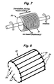
- Figure 7 illustrates an early stage of construction of a second form of superconducting coil.
- This consists of the "writing" of a spiral 21 of textured buffer layer on a cylindrical former 22 using the IBAD technique, by using a fixed ion beam (indicated schematically by an arrow 23) and rotating the former at the same time as translating it - resembling a screw thread cutting operation using a lathe with a "lead screw” which feeds the cutting tool into a work piece.
- This step can be followed by the MOCVD (metal organic vapour deposition) or other process to deposit a YBCO layer (not shown) over the entire cylindrical surface of the former 22, whilst the former is rotated for uniformity of deposition.
- MOCVD metal organic vapour deposition
- the YBCO layer overlies the spiral buffer layer 21, it copies the texture of that underlying buffer layer, and so will be highly superconducting. Where the YBCO layer is deposited on non-textured regions, the superconductivity is two orders of magnitude lower, and can be ignored. In this way, the first layer of a solenoid coil is formed. If necessary, a laser or mechanical scriber (not shown) can be used to cut an isolating region between the highly superconducting turns.
- Another insulating buffer layer (not shown) is then deposited, using any one of a variety of techniques - without using the slow IBAD process, because the buffer layer copies the form of the surface which it overlies.
- the buffer will have a textured surface; and, where the buffer lies on an untextured YBCO surface, the buffer surface will be untextured.
- Another YBCO layer completes the second "winding" of the solenoid, as the new YBCO surface copies the form of the buffer layer which it overlies, and so on until a multilayer solenoid, consisting of concentric cylindrical shells, is built up without the need for a long textured tape. It will be appreciated that the slow IBAD process is only used for the initial textured buffer layer, and after the provision of each reinforcement shell.
- FIG 8 illustrates schematically the former 22 provided with connecting links 24 connected to bond pads 25 provided at the ends of the individual windings.
- the connecting links 24 may be short lengths of tape located within the former 22 on the inside or the outside, before or after film deposition, or they may be tracks of YBCO film deposited before the main coil deposition.
- the former 22 may be grooved, inside or outside, to accept the links 24, and there may be slits cut at an angle at the ends of the former to allow connection of the tracks to the coil ends.
- a shaft encoder (not shown) is used to control accurately the exact rotational position of former 22, thereby permitting precise control of the start and end of each of the "windings", and hence co-location of these starts and ends with the bond pads 25.
- some protective circuitry again integral with the coil, in order to protect the device, or part of the device, against a superconductivity "quench".
- the coil were to be the inner coil of a much larger, conventional superconducting magnet in order to boost the latter's field; then, if the outer sections quenched, the so-called “insert coil” would experience a massive rate of change of flux and hence a massive induced current. This would lead to the destruction of the device.
- the arrangement of Figure 8 is modified by including an FCL (fault current limiter) in each layer of the coil.
- FCL fault current limiter
- Such FCL devices exist in thin film form already, and could be integrated with the coil, either by patterning the ends, or by making "weak links" (layer connections) between the layers, perhaps positioned inside the former 22 before deposition begins. These weak links will fail before the layers fail, thereby preventing the occurrence of the massive induced currents referred to above. This is because an FCL permits the passage of only a predetermined amount of current, and so will fail before coil destruction, provided the predetermined current is chosen to be less than that which would lead to coil destruction.
- a modification of the coil fabrication technique described above with reference to Figure 7 would be to use the length of textured tape (coated or uncoated) to establish the initial textured spiral buffer layer 21. This layer 21 would, therefore, resemble the winding shown in Figure 3 .
- a further embodiment of the invention which is described, by way of example, for the coil fabrication technique described above with reference to Figure 7 , would be to introduce a shell to reinforce the mechanical strength of the coil, and to ensure that after a number of multi-layer coil windings the textured region does not degrade.
- the reinforcement shell could be deposited after the deposition of a number of buffer and superconducting layers, say for example ten, where the cross-section of the coil would appear much like that of Figure 2 , consisting of concentric cylindrical layers.
- the outside surface of the reinforcement shell, once deposited, would require texturing using the same technique as for the texturing of the initial buffer layer.
- One method that could be used to deposit the reinforcement shell would be to position the shell during a shrink-fitting operation.
- the coil fabrication technique proceeds as described above, until a similar number of layers are deposited, say for example ten. This process can then be repeated to produce concentric reinforcement shells within a concentric solenoid, constituting the coil.
- the sections of the concentric solenoid between the concentric reinforcement shells require an interconnection scheme, as between the individual layers of the superconducting coil described above.
- This interconnection scheme would take the form of an FCL device, which would be more economical than having an FCL for each layer of the superconducting coil.
- the FCL devices for the section of concentric solenoid would decouple sections of the coil in the event of a superconducting quench.
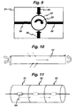
- FIG 9 shows schematically apparatus for forming a modified version of the coil of Figure 7 .
- This apparatus comprises a film deposition chamber 31 which houses a rotatable cylindrical former 32 which is similar to the former 22 of Figure 7 .
- the former 32 is rotatable in the direction of the arrow 33, and the chamber 31 is divided into two portions by means of baffles 34.
- a textured buffer layer (of for example CeO) is deposited on the former 32 by a "line-of-sight" evaporation process, indicated schematically by an arrow 35, whilst YBCO deposition proceeds by a similar "line-of-sight" evaporation process on the other side of the rotating cylindrical former, as indicated schematically by an arrow 36.
- the baffles 34 help maintain the required differential pressures in the two portions of the chamber 31.
- Figure 10 illustrates schematically a coil formation technique which is intermediate the "long coated conductor" technique of Figure 4 and the direct in situ film deposition technique of Figure 7 and 9 .
- a coil is formed in situ by unwinding a reel of a textured flexible substrate 41 formed using the RABiTS approach, and rewinding the sheet onto a former (not shown) to fabricate the coil.
- the sheet 41 could have both sides thereof formed with a textured coating.
- any fabrication process using film deposition techniques heat treatments are inevitably involved, either simultaneously with layer deposition, or after the film deposition process, and the control of oxygenation conditions during such heat treatments is crucial.
- the apparatus of Figure 9 could be modified to provide three contiguous treatment chambers 51, 52 and 53.
- the cylindrical former 54 upon which a coil is to be fabricated, can be shuttled to and from the various chambers 51, 52 and 53 for different treatments, such as film deposition, heat treatment, oxygenation, formation of layer interconnects etc.
- the chamber 51 could be for buffer layer deposition, the chamber 52 for YBCO deposition, and the chamber 53 for brazing/handling operations for the interconnects between layers etc.
- Each of the chambers 51, 52 and 53 is provided with a window (not shown) to allow operator intervention, but it will be appreciated that the majority of processes are under computer control.
- One of the chambers could also be used for forming a textured surface on the cylindrical former 54, using any of a number of processes, including "melt-spinning", where a surface is rotated rapidly while molten metal is sprayed onto it, thereby ensuring that rapid solidification results in a textured finish.
- the different chambers, 51, 52 and 53 of the apparatus of Figure 11 can be used to apply different treatments and processes to the coil as it is made.
- This method is one embodiment of many that can be used to process and heat the coil during its manufacture.
- One aim of these processes and treatments is to control the oxygen content of the coils.
- the oxygen stoichiometry in the layers affects the properties of the superconducting coils. If oxygen is present in the wrong proportion, with respect to the other constituent elements of the superconducting layer, the, superconducting coils will no longer superconduct. So the oxygen content needs to be present within precise limits.
- the coil structure could contain buffer layers that are oxygen sources, oxygen sinks, oxygen gateways, oxygen barriers and, as the situation demands, layers that are permeable to oxygen.
- the properties of the buffer layers are particularly dependant upon the temperatures of their deposition, their heating rates, their cooling rates immediately after deposition, and their other time-temperature histories during processing.
- the most likely geometry for coil fabrication using the film deposition technique is to carry this out on a rotating cylindrical former provided with an integral, preferably internal, heating element. This arrangement would ensure that most of the heating requirements are supplied to raise the temperature sufficiently to ensure the correct epitaxial deposition of layers. If necessary, an additional radiation heating arrangement could be supplied.
- the temperature during a film deposition process must be closely controlled, and this is particularly difficult where a long flat conductor is being processed.
- the presence of an axis of symmetry lends itself to a much better control of uniform heating, for example, by incorporating heating elements inside the cylindrical former, or embedding these in the walls of the cylindrical former.
- Such heating elements may be, for example, tungsten coils or halogen lamps. Complementing this heating arrangement by the use of radiation heating impinging on the external surface of the cylindrical former is also useful for process control, with the main heating being done internally, but the "fine tuning" heating being carried out using external radiation heating methods.
- Figures 12a and 12b are schematic representations of apparatus for forming coils by directly inducing texture on cylindrical surfaces including the process of extrusion.
- Figure 12a shows a cylindrical former 61 around which a sheet 62 of RABiTS material has been wrapped. The sheet 62 is then subjected to rolling and heat treatments using a second (heated) cylinder 63, this treatment eliminating the join in the sheet.
- the two cylinders 61 and 63 thus being a process of performing the texturing in situ.
- Figure 12b shows a modification of the apparatus of Figure 12a , in which the cylinder 61 rotates inside a drum 63 of large diameter.
- a sheet of RABiTS material 62 may be wrapped around the cylinder 61, and the join eliminated by rolling and heat treating, or the texturing process maybe carried out in situ by rotating the two cylinders 61 and 63 relative to one another under pressure to induce texture.
- the arrangement of Figure 12b is actually preferable to that of 12a, as the stresses formed at the surface of the cylinder 61 are more like the conditions reached during the rolling of RABiTS tape.
- the material on the surface of the cylinder 61 is subjected to rolling and heat treatments by a series of cylinders, each of which, as cylinder 62, is in contact with the surface of cylinder 61.
- the series of cylinders texture the material on the surface of cylinder 61 by extrusion in the sense of swaging or drawing the surface of cylinder 61 through a die. The effect of this process is to extrude cylinder 61 along its length.
- the series of cylinders each rotate about an axis perpendicular to the axis of cylinder 61.
- a textured cylinder 71 (the cylindrical surface only of which is shown in Figure 13 ) is co-wound with two tungsten wire heater elements, one of which is immediately unwound leaving an evenly-spaced heater winding 72 in place in contact with the surface of the cylinder, and a "spiral gap" 73 elsewhere.
- the heater winding 72 acts as a "shadow mask" during the process described below.
- the cylinder 71 is then placed inside the deposition chamber 51 of the apparatus of Figure 11 , and is coated with a first buffer layer 74 (see Figure 13 ) using the heater winding 72 to achieve the correct deposition temperature.
- the cylinder 71 is rotated during deposition.
- the buffer layer 74 is deposited using a thermal evaporation source, as indicated by the arrows shown in Figure 13 . This process copies the texture from the cylinder 71.
- that part of the cylinder 71 masked by the heater winding 72 does not receive a buffer layer, so that the situation at this stage is as illustrated in the cross-sectional view of Figure 14 .
- the buffer layer 74 thus forms a spiral track between the turns of the heater winding 72.
- the cylinder 71 is then moved into the chamber 52 of the apparatus of Figure 11 , where it receives a YBCO coating, again with that part of the cylinder underneath the heater winding 72 being left uncoated. This process copies the texture from the buffer layer 74 to the YBCO layer (not shown in Figures 13 and 14 ).
- the cylinder 71 is then passed back to the chamber 51, where it receives another buffer layer on top of the spiral YBCO track which then exists.
- the cylinder 71 is then passed to the chamber 53, where it is re-wound with the second heater element (not shown), after which the first heater winding 72 is removed, thereby leaving the spiral YBCO track with an insulating textured buffer layer on top, as the first "coil winding". Spaces are left in between the spiral coil winding turns which are uncoated, bare cylinder of the same dimensions as the spiral track.
- the cylinder 71 is then returned to the chamber 51 and receives another insulating buffer layer. This layer is deposited on top of the previously-masked part of the bare cylinder. Subsequently, a YBCO film is deposited in the chamber 52, and the cylinder 71 is then passed back to the chamber 51 for application of another buffer layer. The cylinder 71 is then passed to the chamber 53, where the first heater winding is re-wound and the second heater winding is removed. Connections between the first and second windings can be made using a similar scheme to that shown in Figure 8 , this process being carried out in the chamber 53. At this point, there are two YBCO layers in the form of windings, both with textured insulating buffer layers on top.
- the diameter of the heater windings maybe typically 200-500 microns, whereas the layer thicknesses are generally of the order of a few microns.
- Figures 13-15 are not drawn to scale; but, if the sources for thermal evaporation are some centimetres away, this gives a sharp masking effect with very little "penumbra” effect. It will also be appreciated that, during depositions steps subsequent to the first, the position of the next heater winding will be displaced exactly by the diameter of the wire of the heater windings.
- the structure shown in Figure 15 forms a simple, four-layer coil, and the layers must be connected, either in series or in parallel, depending upon the preferred power supply.
- the cylinder ends can be in the form of film FCLs (either pre-deposited or post-deposited), such that the layers are connected through the FCL film devices.
- FCLs film FCLs
- each layer In order to maintain the same direction of current through the spiral YBCO tracks comprising the "coil windings", each layer must be connected to the opposite end of the next layer, via some internal superconducting link via a respective FCL device.
- the heater windings themselves may be deposited using film deposition techniques at each stage, and can be removed using an etching process after photolithography. In this sense, they would be "sacrificial" rather than reusable as was the case with the process described above.
- Another variation would be to cut a spiral groove in the textured cylinder surface and to use this to embed a heater winding, with the winding standing proud of the surface.
- a textured multilayer structure is then built up on the adjacent sections, geometrically similar to the scheme of Figure 8 , and the heater winding can be removed after the final deposition stage. This simplifies the process, but does not achieve quite the same current density as the co-wound, double heater winding approach described above.
- the delineation of the coils may be accomplished using photolithographic techniques, and a careful choice of the chemical etchants to distinguish between etching of the buffer and YBCO layers. In this way, "etch stop" techniques can be used, which increases the tolerance of the processing.
- film deposition can be accomplished using the so-called “dip coating” or other "thick film” technique, whereby the film is supplied by rotating the cylinder in a solution of, for example, sol-gel of cerium oxide.
- coil fabrication techniques above all refer to the use of a substantially cylindrical former.
- coils can be manufactured upon any curved surface, including a saddle, a cone, a surface having a concave rather than a convex surface, a surface with negative curvature rather than a surface with positive curvature, and a surface that does not have an axis of rotation.
- the films that are described in the above methods are of the order of micrometers.
- thin films as used in the semiconductor industry or for optical coatings, are a few hundred nanometers thick.
- Thick films on the other hand, as used in printed circuit boards, are tens to hundreds of microns thick.
- the HTS films fall between the definitions of thick and thin films.
- HTS and buffer films have a thickness that lies between the definition of thin films and thick films
- both thin film deposition methods such as evaporation, sputtering, MOCVD, and thick film deposition methods, such as "dip-coating", spray pyrolysis and, spin coating can be used to make HTS films.
- a concentric solenoid with 100 thick layers is likely to be easier to manufacture than a concentric solenoid with 1000 thin layers.
- any material - particularly magnesium diboride or ReBCO (of which YBCO is a common example, as Re denotes any rare earth element) - which, as a film, exhibits high temperature superconducting properties could be used for the manufacturing processes and articles described herein.
- any material which exhibits the physical properties of the buffer layers can be used in buffer layers acting, for example, as seed layers, insulators, or chemical barriers or combinations of these in the manufacturing processes and articles described herein. It is also common to have more than one buffer layer underneath the HTS film layer.
- Specific process and approaches have been referred to above: such as RABiTS, in the context of ensuring a textured HTS layer whereby the necessary biaxial texture is imparted to a metallic substrate by a combination of rolling reductions and heat treatments; and in other cases IBAD, ISD and IAD, where the necessary biaxial seed layer is produced on a randomly-oriented substrate by depositing a buffer layer in such a way that it is textured.
- RABiTS in the context of ensuring a textured HTS layer whereby the necessary biaxial texture is imparted to a metallic substrate by a combination of rolling reductions and heat treatments
- IBAD, ISD and IAD where the necessary biaxial seed layer is produced on a randomly-oriented substrate by depositing a buffer
- Such variants of those processes can include: texturing a cylinder by extrusion or melt texturing instead of rolling, or by molecular beam epitaxy (MBE), or hot dipping in a suitable flux.
- the texturing process may be driven by gradients in pressure, temperature or other physical parameters.
- the present invention provides a method of fabricating a superconducting coil, the method comprising the step of fabricating individual coil windings by depositing and shaping electrically-conductive material in situ on a substantially cylindrical former.
- the method further comprises the step of depositing and shaping buffer layers between successive coil windings.
- the electrically-conductive material is deposited on the former by a thin film deposition technique, and the buffer layers are deposited by a thin film deposition technique.
- the method comprises an intial step of forming a spiral of textured buffer layer on the former and the textured buffer layer is formed by helically positioning a flexible textured tape onto the former.
- the spiral textured buffer layer is formed by this thin deposition technique.
- the thin film deposition technique includes the step of forming a spiral of textured buffer layer on the former, depositing an electrically-conductive layer over the spiral buffer layer to form a first coil winding, depositing a second buffer layer onto the electrically-conductive layer, and depositing a second electrically-conductive layer onto the second buffer layer, thereby forming a second winding of the coil, and repeating the buffer layer and electrically-conductive layer depositions to form as many coil windings as required, each deposition process being such as to transfer the texture of the underlying layer to the newly-deposited layer.
- the spiral of textured buffer layers may be written onto the former using the IBAD technique using a fixed ion beam and rotating and translating the former.
- the ion beam is translated and the former is rotated but not translated.
- Another possibility would be to form a buffer layer completely overlying a textured cylindrical former, and then removing a spiral track of the buffer layer (for example lithographically) to form the spiral of textured buffer layers.
- each of the electrically-conductive layers is an YBCO layer.
- each of the electrically-conductive layers is any other suitable superconducting film such as a rare earth barium copper oxide (ReBCO) film.
- ReBCO rare earth barium copper oxide
- the method further comprises providing connecting links to connect the ends of adjacent coil windings.
- the connecting links are provided within the former, and each includes a fault current limiter.
- the deposition steps take place in a film deposition chamber, and deposition of the buffer layers occurs from one side of the chamber, and deposition of the electrically-conductive layers occurs from the opposite side of the chamber, and the former is rotated during the deposition process.
- the two sides of the deposition chamber may be separated by baffles.
- the former is provided with a textured cylindrical surface, and with a spirally-wound heater winding wire, the turns of which are spaced by the diameter of the wire, a first buffer layer is deposited to form a spiral buffer layer track between the turns of the heater winding, an electrically-conductive layer is deposited over the first buffer layer, and a further buffer layer is deposited on top of the superconductive layer to form a first coil winding, a second heater winding wire is wound between the turns of the first heater winding wire, the first heater winding is removed, and a second coil winding is formed, the second coil winding being constituted by a first deposited buffer layer, a deposited superconductive layer and a second deposited buffer layer, and the process is repeated to form additional coil windings as required, each deposition process being such as to transfer the texture of the underlying layer to the newly-deposited layer.
- the method may further comprise the step of circulating coolant within the former, and/ or of testing, in situ, each coil winding.
- the invention also provides a method of making a multilayered textured superconducting coil, the method including the steps of fabricating superconductor coil windings and insulating layers by film deposition means, whereby the films are patterned by masking or machining operations before or after film deposition, in-situ or ex-situ, and/or by subsequently patterning using lithographic techniques allowing a tailoring of coil properties by changing the geometry (width, thickness) of the superconducting paths at every point on the surface.
- the invention further provides a method of fabricating a superconducting coil, the method comprising the step of helically positioning a flexible coated tape onto a substantially cylindrical former, the coated tape being constituted by an insulating buffer layer and a coating of electrically-conductive material.
- YBCO constitutes the electrically-conductive material
- the tape is a textured substrate made, for example, by the RABiTS process.
- the former is generally barrel-shaped, with tapered portions at each end of a cylindrical control main portion.
- the term “texture” (see Chambers Dictionary of Science & Technology) should be taken to mean “the physical appearance in terms of roughness and shape of surface features; in microscopical examination it relates to microstructural features such as grain shape, distribution of phases, and crystallographic orientation”.
- Another well known definition is "generally, the texture of a material, such as the texture of a thin film superconductor, is detected by way of x-ray or neutron defraction, electron back scattering defraction, and other techniques that use an electron beam, such as an electron microscope”.
- texture is crystallographic texture or preferred crystallographic orientation.
- the texture of a sample of superconducting material is indicative of the superconducting properties of that sample.
Landscapes
- Engineering & Computer Science (AREA)
- Power Engineering (AREA)
- Manufacturing & Machinery (AREA)
- Superconductors And Manufacturing Methods Therefor (AREA)
- Particle Accelerators (AREA)
- Multiple-Way Valves (AREA)
- Extrusion Moulding Of Plastics Or The Like (AREA)
Claims (26)
- Ein Verfahren zur Herstellung einer supraleitenden Spule durch erzeugen einzelner Spulenwicklungen durch ein Abscheiden, formen und strukturieren eines supraleitenden Materials und eines Puffermaterials mit einem in situ Formgeber, der eine im Wesentlichen gewölbte Oberfläche aufweist und das Verfahren die folgenden Schritte umfasst:• Ausbilden einer initialen, strukturierten Pufferschicht auf dem Formergeber,• Aufbringen einer ersten Schicht eines supraleitenden Materials auf die strukturierte Pufferschicht, so das hierdurch die kristallografische Struktur der strukturierten Pufferschicht die erste Schicht des supraleitenden Materials nachbildet,• Aufbringen einer zweiten Pufferschicht auf die erste Schicht des supraleitenden Materials, so das hierdurch die kristallografische Struktur der ersten Schicht des supraleitenden Materials die zweite Pufferschicht nachbildet,• Aufbringen einer zweiten Schicht eines supraleitenden Materials auf die zweite Pufferschicht, so dass hierdurch die kristallografische Struktur der zweiten Pufferschicht die zweite Schicht des supraleitenden Materials nachbildet und• wechsellagiges Aufbringen weiterer Pufferschichten und Schichten eines supraleitenden Materials, so dass hierdurch die kristallografische Struktur einer jeden Schicht zu jeder darüber liegenden Schicht nachgebildet wird und das Aufbringen und Formen schrittweise durch die Spulenwicklungen in den Schichten des supraleitenden Materials erfolgt.
- Ein Verfahren nach Anspruch 1, wobei der Formgeber im Wesentlichen eine zylindrische Oberfläche aufweist.
- Ein Verfahren nach Anspruch 2, wobei der Formgeber im Wesentlichen als eine kreiskegelförmige Oberfläche aufweist.
- Ein Verfahren nach einem der Ansprüche 1 bis 3, wobei jede Schicht des supraleitenden Materials an den Formgeber mittels einer Aufbringtechnik eines Films anlagerbar ist.
- Ein Verfahren nach einem der Ansprüche 1 bis 4, wobei jede der zweiten Pufferschichten und jede weitere Pufferschichten mittels einer Aufbringtechnik eines Films anlagerbar sind.
- Ein Verfahren nach einem der Ansprüche 1 bis 5, wobei die initiale, strukturierte Pufferschicht durch ein schraubenartiges, flexibles strukturiertes Band ausgebildet wird, das im Formgeber vorgesehen ist.
- Ein Verfahren nach einem der Ansprüche 1 bis 5, wobei die initiale strukturierte Pufferschicht durch eine Aufbringtechnik eines Films anlagerbar ist.
- Ein Verfahren nach einem der Ansprüche 1 bis 7, wobei der Formgeber sich bei jedem Anlagerungsvorgang dreht.
- Ein Verfahren nach Anspruch 8, wobei der Formgeber während jedes Anlagerungsschrittes translatiert.
- Ein Verfahren nach einem der vorhergehenden Ansprüche 1 bis 5, wobei initiale, strukturierte Pufferschicht auf den Formgeber unter Verwendung der IBAD-Technik geschrieben wird, unter der Verwendung eines festgelegten Ionenstrahls und mittels einem Drehen und Tranlatieren des Formgebers.
- Ein Verfahren nach einem der vorhergehenden Ansprüche 1 bis 10, wobei jede Schicht des supraleitenden Materials eine YBCO Schicht ist.
- Ein Verfahren nach einen der vorhergehenden Ansprüche 1 bis 11, des Weiteren umfassend:• Ausbilden einer verstärkten Schale um die Spule herum, nachdem die Schichten des supraleitenden Materials angelagert worden sind,• Ausbilden einer strukturierten Schicht auf der Oberfläche der verstärkten Schale, um hierdurch eine weitere Pufferschicht auszubilden, unter der Verwendung des gleichen Herstellungsprozesses wie dieser für die originalen Pufferschicht verwendet wird,• Ausbilden weiterer Spulenwicklungen durch Anlagerung weiterer, folgegebundener supraleitender Schichten und Pufferschichten.
- Ein Verfahren nach einem der vorhergehenden Ansprüche 1 bis 12, des Weiteren umfassend:Bereitstellen eines Verbindungsmittels, dass die angrenzenden Enden der benachbarten Spulenwicklungen miteinander verbinden.
- Ein Verfahren nach Anspruch 13, wobei die Verbindungsmittel innerhalb des Formgebers vorgesehen sind.
- Ein Verfahren nach einem Der Ansprüche 1 bis 14, wobei jedes der Verbindungsmittel eine Begrenzung für einen Fehlerstrom umfasst.
- Ein Verfahren nach einem der vorhergehenden Ansprüche 1 bis 15, wobei der Schritt der Anlagerung in einer Kammer zum Aufbringen eines Films erfolgt.
- Ein Verfahren nach Anspruch 16, wobei die Anlagerung der Pufferschichten von einer Seite der Kammer her erfolgt, und die Anlagerung der supraleitenden Schichten von der gegenüberliegenden Seite der Kammer her erfolgt, und der Formgeber währende des Anlagerungsvorganges dabei rotiert.
- Ein Verfahren nach Anspruch 17, wobei die zwei Seiten der Anlagerungskammer durch Blenden voneinander getrennt sind.
- Ein Verfahren nach einem der vorhergehenden Ansprüche 1 bis 16, wobei der Formergeber mit einem spiralförmig, gewundenen Heizdraht versehen ist und die Windungen durch ein Mittel zur Beabstandung voneinander beabstandet ausgebildet sind, eine erste Pufferschicht angelagert wird, um eine spiralförmige Pufferschichtspur auszubilden, die zwischen den Windungen des Heizdrahtes liegt und eine supraleitende Schicht ist auf der ersten Pufferschicht angelagert und eine weitere Pufferschicht ist wiederum auf der supraleitenden Schicht angelagert, um hierdurch die erste Spulenwicklung auszubilden, ein zweiter spiralförmige ausgebildeter Heizdraht sich zwischen den Windungen des ersten gewundenen Heizdrahtes windet, der erste gewundene Heizdraht sodann entfernt wird und die zweite Spulenwicklung ausgebildet ist und die zweite Spulenwicklung durch die erste angelagerte Pufferschicht, eine angelagerte supraleitende Schicht und eine zweite angelagerte Pufferschicht besteht, und der Vorgang solange wiederholbar ist, bis die gewünschte Anzahl an Spulenwicklungen erreicht ist, wobei jeder Anlagerungsvorgang derart ausgeführt wird, dass die Struktur der zu unterst liegende Schicht auf die neu angelagerte Schicht übertragen wird.
- Ein Verfahren nach Anspruch 19, wobei das Mittel zur Beabstandung der Windungen der spiralförmig ausgebildeten Heizwicklung dem Durchmesser des Heizwicklungsdrahtes entspricht.
- Ein Verfahren nach Anspruch 19, wobei das Mittel zur Beabstandung der Windungen der spiralförmig ausgebildeten Heizwicklung ein Mittel ist, dass durch die Auskehlungen der Windungen des Formgebers ausgebildet wird.
- Ein Verfahren nach einem der vorhergehenden Ansprüche 1 bis 21, des Weiteren den Schritt eines im Formgeber zirkulierend geführten Kühlmittels umfassend.
- Ein Verfahren nach einem der vorhergehenden Ansprüche 1 bis 22, des Weiteren den Schritt eines in situ Test der Strukturierung und/oder der supraleitenden Eigenschaften einer jeden Spulenwicklung umfasst.
- Ein Verfahren nach einem der vorhergehenden Ansprüche 1 bis 23, des Weiteren den Schritt der Herstellung der Spulenwicklungen und der Pufferschichten durch ein Aufbringmittel eins Films umfasst, wobei die aufgebrachten Filme durch ein Maskieren oder eine maschinelle Bearbeitung gemustert werden, bevor oder nachdem der Film aufgebracht wird.
- Ein Verfahren nach einem der vorhergehenden Ansprüche 1 bis 23, des Weiteren den Schritt der Herstellung der Spulenwicklungen und der Pufferschichten durch ein Aufbringmittel eines Films umfasst, wobei die Filme in situ gemustert werden.
- Ein Verfahren nach einem oder mehreren der vorhergehenden Ansprüche 1 bis 23, des Weiteren den Schritt der Herstellung der Spulenwicklungen und der Pufferschichten durch ein Aufbringmittel eines Films umfasst, wobei die Filme nachträglich durch die Verwendung von lithographischen Techniken gemustert werden, die eine Konfektionierung der Eigenschaften der Spulen durch die Kontrolle der Geometrie(über Querschnitt, Dicke, Beabstandung oder Anstellwinkel) der supraleitenden Wege an jeden Punkt der Oberfläche erlauben.
Applications Claiming Priority (3)
| Application Number | Priority Date | Filing Date | Title |
|---|---|---|---|
| GB0120697 | 2001-08-24 | ||
| GBGB0120697.8A GB0120697D0 (en) | 2001-08-24 | 2001-08-24 | Superconducting coil fabrication |
| PCT/GB2002/003898 WO2003019589A1 (en) | 2001-08-24 | 2002-08-23 | Superconducting coil fabrication |
Publications (2)
| Publication Number | Publication Date |
|---|---|
| EP1421592A1 EP1421592A1 (de) | 2004-05-26 |
| EP1421592B1 true EP1421592B1 (de) | 2010-10-06 |
Family
ID=9920989
Family Applications (1)
| Application Number | Title | Priority Date | Filing Date |
|---|---|---|---|
| EP02755238A Expired - Lifetime EP1421592B1 (de) | 2001-08-24 | 2002-08-23 | Neue herstellungsverfahren einer spule |
Country Status (6)
| Country | Link |
|---|---|
| US (1) | US8061016B2 (de) |
| EP (1) | EP1421592B1 (de) |
| AT (1) | ATE484064T1 (de) |
| DE (1) | DE60237903D1 (de) |
| GB (1) | GB0120697D0 (de) |
| WO (1) | WO2003019589A1 (de) |
Families Citing this family (27)
| Publication number | Priority date | Publication date | Assignee | Title |
|---|---|---|---|---|
| JP4122833B2 (ja) * | 2002-05-07 | 2008-07-23 | 株式会社日立製作所 | 二ホウ化マグネシウムを用いたnmr装置用プローブ |
| JP2003329756A (ja) * | 2002-05-08 | 2003-11-19 | Hitachi Ltd | 超高感度核磁気共鳴イメージング装置 |
| GB0305146D0 (en) | 2003-03-06 | 2003-04-09 | Coated Conductors Consultancy | Superconducting coil testing |
| JP3993127B2 (ja) * | 2003-04-24 | 2007-10-17 | 株式会社日立製作所 | Nmr装置用超電導プローブコイル |
| KR100586570B1 (ko) * | 2004-11-25 | 2006-06-07 | 엘에스전선 주식회사 | 크랙 방지 구조를 갖는 초전도 선재 |
| JP2007073623A (ja) * | 2005-09-05 | 2007-03-22 | Kobe Steel Ltd | 超電導コイル製造用巻枠および超電導ソレノイド巻コイル |
| US7319327B2 (en) * | 2005-11-17 | 2008-01-15 | General Electric Company | Magnetic resonance imaging system with reduced cooling needs |
| GB2432726B (en) * | 2005-11-25 | 2008-06-18 | Coated Conductors Consultancy | Template for a superconducting coil |
| KR100662754B1 (ko) * | 2005-12-02 | 2007-01-02 | 엘에스산전 주식회사 | 초전도 저항형 한류기 |
| US7879763B2 (en) * | 2006-11-10 | 2011-02-01 | Superpower, Inc. | Superconducting article and method of making |
| JP4743150B2 (ja) * | 2007-04-17 | 2011-08-10 | 住友電気工業株式会社 | 超電導コイルおよびそれに用いる超電導導体 |
| KR100945201B1 (ko) * | 2007-10-31 | 2010-03-03 | 한국전기연구원 | 안정화재가 형성된 초전도 박막선재 및 그의 접합방법 |
| EP2131408B1 (de) * | 2008-06-02 | 2011-09-07 | Nexans | Verfahren für die Herstellung eines geformten Substrats für einen beschichteten Leiter und beschichteter Leiter mit dem Substrat |
| EP2131407A1 (de) * | 2008-06-05 | 2009-12-09 | Nexans | Supraleitender Draht mit geringen Wechselstromverlusten |
| DE102008060757A1 (de) * | 2008-12-05 | 2010-06-17 | Forschungszentrum Jülich GmbH | Vorrichtung zur Erzeugung eines homogenen Magnetfeldes und Optimierungsverfahren |
| EP2333133B1 (de) * | 2009-11-23 | 2013-03-06 | Linde Aktiengesellschaft | Verfahren zur Herstellung einer mehrlagigen Spule |
| US8427148B2 (en) * | 2009-12-31 | 2013-04-23 | Analogic Corporation | System for combining magnetic resonance imaging with particle-based radiation systems for image guided radiation therapy |
| DE102011081465A1 (de) * | 2011-08-24 | 2013-02-28 | Siemens Aktiengesellschaft | Verfahren zur Herstellung von supraleitenden Spulen und Vorrichtung mit einer supraleitenden Spule hergestellt nach dem Verfahren |
| US11978571B2 (en) * | 2013-05-03 | 2024-05-07 | Christopher M. Rey | Method of coiling a superconducting cable with clocking feature |
| WO2014181462A1 (ja) * | 2013-05-10 | 2014-11-13 | 富士通株式会社 | 充電池、充電システム、及び電子機器 |
| DE102015218019B4 (de) | 2015-09-18 | 2019-02-28 | Bruker Biospin Gmbh | Kryostat mit Magnetanordnung, die einen LTS-Bereich und einen HTS-Bereich umfasst |
| CN108303596B (zh) * | 2018-01-16 | 2024-07-02 | 宁波市计量测试研究院(宁波市衡器管理所、宁波新材料检验检测中心) | 一种利用薄膜沉积技术制作超薄线圈的方法及超薄线圈 |
| CN112951584B (zh) * | 2021-01-25 | 2023-01-03 | 西安聚能超导磁体科技有限公司 | 一种超导磁体单根不断线连续绕制塑形装置的使用方法 |
| CN114360894B (zh) * | 2022-01-13 | 2023-10-27 | 中国科学院电工研究所 | 一种闭环超导磁体的绕制方法及闭环超导磁体 |
| JP2025511925A (ja) * | 2022-04-04 | 2025-04-16 | ルネサンス・フュージョン | 超電導コイルを製造するための方法及びデバイス |
| EP4258298A1 (de) * | 2022-04-04 | 2023-10-11 | Renaissance Fusion | Verfahren zum herstellen von supraleitenden spulen und vorrichtung |
| WO2025038700A2 (en) * | 2023-08-15 | 2025-02-20 | The Trustees Of Princeton University | Method for reinforcement, quench protection, and stabilization of large all-metal superconducting magnets |
Family Cites Families (14)
| Publication number | Priority date | Publication date | Assignee | Title |
|---|---|---|---|---|
| DE2734410C3 (de) * | 1977-07-29 | 1980-04-17 | Siemens Ag, 1000 Berlin Und 8000 Muenchen | Verfahren zur Herstellung eines Supraleiters |
| JPS63250881A (ja) | 1987-04-07 | 1988-10-18 | Semiconductor Energy Lab Co Ltd | 超電導体の作製方法 |
| US5096882A (en) | 1987-04-08 | 1992-03-17 | Hitachi, Ltd. | Process for controlling oxygen content of superconductive oxide, superconductive device and process for production thereof |
| JPS63291405A (ja) | 1987-05-25 | 1988-11-29 | Fujikura Ltd | 超電導コイルの製造方法 |
| JPS6411305A (en) | 1987-07-06 | 1989-01-13 | Sumitomo Electric Industries | Superconducting coil and manufacture thereof |
| US4845308A (en) * | 1987-07-20 | 1989-07-04 | The Babcock & Wilcox Company | Superconducting electrical conductor |
| US5225394A (en) * | 1987-08-31 | 1993-07-06 | Semiconductor Energy Laboratory Co., Ltd. | Method for manufacturing high Tc superconducting circuits |
| US5079222A (en) | 1987-08-31 | 1992-01-07 | Semiconductor Energy Laboratory Co., Ltd. | Superconducting ceramic circuits and manufacturing method for the same |
| JPH01276605A (ja) * | 1988-04-27 | 1989-11-07 | Hokuriku Electric Power Co Inc:The | 超電導マグネットの製造方法 |
| JPH04324605A (ja) * | 1991-04-24 | 1992-11-13 | Toshiba Corp | 超電導コイルの製造方法 |
| US5741377A (en) * | 1995-04-10 | 1998-04-21 | Martin Marietta Energy Systems, Inc. | Structures having enhanced biaxial texture and method of fabricating same |
| KR100276003B1 (ko) | 1998-09-30 | 2000-12-15 | 윤덕용 | 띠형 기판 상의 박막 형성장치 및 박막 형성방법 |
| EP1122799A1 (de) | 2000-02-01 | 2001-08-08 | Zentrum für Funktionswerkstoffe, Gemeinnützige Gesellschaft mbH | Substrat aus rostfreiem Stahl für Supraleiterschichten |
| JP4324605B2 (ja) * | 2006-06-29 | 2009-09-02 | ピーティー ブカカ テクニック ウタマ | ボーディングブリッジ |
-
2001
- 2001-08-24 GB GBGB0120697.8A patent/GB0120697D0/en not_active Ceased
-
2002
- 2002-08-23 EP EP02755238A patent/EP1421592B1/de not_active Expired - Lifetime
- 2002-08-23 WO PCT/GB2002/003898 patent/WO2003019589A1/en not_active Ceased
- 2002-08-23 US US10/487,537 patent/US8061016B2/en not_active Expired - Fee Related
- 2002-08-23 AT AT02755238T patent/ATE484064T1/de not_active IP Right Cessation
- 2002-08-23 DE DE60237903T patent/DE60237903D1/de not_active Expired - Lifetime
Also Published As
| Publication number | Publication date |
|---|---|
| US20050028347A1 (en) | 2005-02-10 |
| EP1421592A1 (de) | 2004-05-26 |
| DE60237903D1 (de) | 2010-11-18 |
| GB0120697D0 (en) | 2001-10-17 |
| US8061016B2 (en) | 2011-11-22 |
| WO2003019589A1 (en) | 2003-03-06 |
| ATE484064T1 (de) | 2010-10-15 |
Similar Documents
| Publication | Publication Date | Title |
|---|---|---|
| EP1421592B1 (de) | Neue herstellungsverfahren einer spule | |
| AU696169B2 (en) | Superconducting magnetic coil | |
| US6603379B1 (en) | Superconducing wind-and-react-coils and methods of manufacture | |
| EP0423354B2 (de) | Draht aus supraleiteroxyd, verfahren zur herstellung und so erzeugter gegenstand | |
| EP0472333B1 (de) | Ausgedehnte supraleitende Elemente bestehend aus Supraleitern und supraleitenden Spulen | |
| EP0772208B1 (de) | Spule aus supraleitendem Oxid und ein Verfahren zu deren Herstellung | |
| US5189260A (en) | Strain tolerant microfilamentary superconducting wire | |
| Iijima et al. | Development of long Y-123 coated conductors for coil-applications by IBAD/PLD method | |
| Sharma | Practical Cuprate Superconductors | |
| Ayai et al. | Improvement of critical current density and residual resistivity on jelly-roll processed Nb/sub 3/Al superconducting wires | |
| US11798721B2 (en) | High-Tc superconducting electromagnet for persistent current operation | |
| JPH0395806A (ja) | 超電導々体及びその超電導々体を用いて形成した超電導コイル | |
| US5758405A (en) | Consumable mandrel for superconducting magnetic coils | |
| JP3158408B2 (ja) | 酸化物超電導線材およびその製造方法 | |
| AU739105B2 (en) | Superconducting magnetic coil | |
| EP4595085B1 (de) | Verwendung eines supraleiterdrahts zur elektrischen verbindung benachbarter feldspulen in einem magnetresonanzbildgebungskryostat | |
| JP3675605B2 (ja) | 酸化物超電導コイルの製造方法及び酸化物超電導コイル製造用巻枠。 | |
| JPH05266726A (ja) | 酸化物超電導線 | |
| JP2651018B2 (ja) | 高磁場マグネット | |
| AU709072B2 (en) | Method of making superconducting wind-and-react coils | |
| JPH01203298A (ja) | 酸化物セラミツク超電導材料を備えた細長い導体の製造方法と装置 | |
| JP2835069B2 (ja) | 超電導コイル | |
| JP2844632B2 (ja) | 酸化物超電導線材およびその製造方法 | |
| JP3016295B2 (ja) | 磁気シールド体およびその製造方法 | |
| LI et al. | Beschichteter Leiter Conducteur revêtu |
Legal Events
| Date | Code | Title | Description |
|---|---|---|---|
| PUAI | Public reference made under article 153(3) epc to a published international application that has entered the european phase |
Free format text: ORIGINAL CODE: 0009012 |
|
| 17P | Request for examination filed |
Effective date: 20040323 |
|
| AK | Designated contracting states |
Kind code of ref document: A1 Designated state(s): AT BE BG CH CY CZ DE DK EE ES FI FR GB GR IE IT LI LU MC NL PT SE SK TR |
|
| AX | Request for extension of the european patent |
Extension state: AL LT LV MK RO SI |
|
| RAP1 | Party data changed (applicant data changed or rights of an application transferred) |
Owner name: COATED CONDUCTORS CONSULTANCY LTD. |
|
| RAP1 | Party data changed (applicant data changed or rights of an application transferred) |
Owner name: COATED CONDUCTOR CYLINDERS LIMITED |
|
| 17Q | First examination report despatched |
Effective date: 20081119 |
|
| RAP1 | Party data changed (applicant data changed or rights of an application transferred) |
Owner name: 3-CS LTD. |
|
| GRAP | Despatch of communication of intention to grant a patent |
Free format text: ORIGINAL CODE: EPIDOSNIGR1 |
|
| GRAS | Grant fee paid |
Free format text: ORIGINAL CODE: EPIDOSNIGR3 |
|
| GRAA | (expected) grant |
Free format text: ORIGINAL CODE: 0009210 |
|
| AK | Designated contracting states |
Kind code of ref document: B1 Designated state(s): AT BE BG CH CY CZ DE DK EE ES FI FR GB GR IE IT LI LU MC NL PT SE SK TR |
|
| REG | Reference to a national code |
Ref country code: GB Ref legal event code: FG4D |
|
| REG | Reference to a national code |
Ref country code: CH Ref legal event code: EP |
|
| REG | Reference to a national code |
Ref country code: IE Ref legal event code: FG4D |
|
| REF | Corresponds to: |
Ref document number: 60237903 Country of ref document: DE Date of ref document: 20101118 Kind code of ref document: P |
|
| REG | Reference to a national code |
Ref country code: NL Ref legal event code: T3 |
|
| REG | Reference to a national code |
Ref country code: CH Ref legal event code: NV Representative=s name: KELLER & PARTNER PATENTANWAELTE AG |
|
| PG25 | Lapsed in a contracting state [announced via postgrant information from national office to epo] |
Ref country code: FI Free format text: LAPSE BECAUSE OF FAILURE TO SUBMIT A TRANSLATION OF THE DESCRIPTION OR TO PAY THE FEE WITHIN THE PRESCRIBED TIME-LIMIT Effective date: 20101006 Ref country code: PT Free format text: LAPSE BECAUSE OF FAILURE TO SUBMIT A TRANSLATION OF THE DESCRIPTION OR TO PAY THE FEE WITHIN THE PRESCRIBED TIME-LIMIT Effective date: 20110207 Ref country code: SE Free format text: LAPSE BECAUSE OF FAILURE TO SUBMIT A TRANSLATION OF THE DESCRIPTION OR TO PAY THE FEE WITHIN THE PRESCRIBED TIME-LIMIT Effective date: 20101006 Ref country code: BG Free format text: LAPSE BECAUSE OF FAILURE TO SUBMIT A TRANSLATION OF THE DESCRIPTION OR TO PAY THE FEE WITHIN THE PRESCRIBED TIME-LIMIT Effective date: 20110106 Ref country code: AT Free format text: LAPSE BECAUSE OF FAILURE TO SUBMIT A TRANSLATION OF THE DESCRIPTION OR TO PAY THE FEE WITHIN THE PRESCRIBED TIME-LIMIT Effective date: 20101006 |
|
| PG25 | Lapsed in a contracting state [announced via postgrant information from national office to epo] |
Ref country code: GR Free format text: LAPSE BECAUSE OF FAILURE TO SUBMIT A TRANSLATION OF THE DESCRIPTION OR TO PAY THE FEE WITHIN THE PRESCRIBED TIME-LIMIT Effective date: 20110107 Ref country code: BE Free format text: LAPSE BECAUSE OF FAILURE TO SUBMIT A TRANSLATION OF THE DESCRIPTION OR TO PAY THE FEE WITHIN THE PRESCRIBED TIME-LIMIT Effective date: 20101006 |
|
| PG25 | Lapsed in a contracting state [announced via postgrant information from national office to epo] |
Ref country code: ES Free format text: LAPSE BECAUSE OF FAILURE TO SUBMIT A TRANSLATION OF THE DESCRIPTION OR TO PAY THE FEE WITHIN THE PRESCRIBED TIME-LIMIT Effective date: 20110117 Ref country code: EE Free format text: LAPSE BECAUSE OF FAILURE TO SUBMIT A TRANSLATION OF THE DESCRIPTION OR TO PAY THE FEE WITHIN THE PRESCRIBED TIME-LIMIT Effective date: 20101006 Ref country code: CZ Free format text: LAPSE BECAUSE OF FAILURE TO SUBMIT A TRANSLATION OF THE DESCRIPTION OR TO PAY THE FEE WITHIN THE PRESCRIBED TIME-LIMIT Effective date: 20101006 |
|
| PLBE | No opposition filed within time limit |
Free format text: ORIGINAL CODE: 0009261 |
|
| STAA | Information on the status of an ep patent application or granted ep patent |
Free format text: STATUS: NO OPPOSITION FILED WITHIN TIME LIMIT |
|
| PG25 | Lapsed in a contracting state [announced via postgrant information from national office to epo] |
Ref country code: DK Free format text: LAPSE BECAUSE OF FAILURE TO SUBMIT A TRANSLATION OF THE DESCRIPTION OR TO PAY THE FEE WITHIN THE PRESCRIBED TIME-LIMIT Effective date: 20101006 Ref country code: SK Free format text: LAPSE BECAUSE OF FAILURE TO SUBMIT A TRANSLATION OF THE DESCRIPTION OR TO PAY THE FEE WITHIN THE PRESCRIBED TIME-LIMIT Effective date: 20101006 |
|
| 26N | No opposition filed |
Effective date: 20110707 |
|
| REG | Reference to a national code |
Ref country code: DE Ref legal event code: R097 Ref document number: 60237903 Country of ref document: DE Effective date: 20110707 |
|
| PG25 | Lapsed in a contracting state [announced via postgrant information from national office to epo] |
Ref country code: MC Free format text: LAPSE BECAUSE OF NON-PAYMENT OF DUE FEES Effective date: 20110831 |
|
| PG25 | Lapsed in a contracting state [announced via postgrant information from national office to epo] |
Ref country code: LU Free format text: LAPSE BECAUSE OF NON-PAYMENT OF DUE FEES Effective date: 20110823 Ref country code: CY Free format text: LAPSE BECAUSE OF EXPIRATION OF PROTECTION Effective date: 20101006 |
|
| PGFP | Annual fee paid to national office [announced via postgrant information from national office to epo] |
Ref country code: TR Payment date: 20140731 Year of fee payment: 13 |
|
| REG | Reference to a national code |
Ref country code: CH Ref legal event code: PCAR Free format text: NEW ADDRESS: EIGERSTRASSE 2 POSTFACH, 3000 BERN 14 (CH) |
|
| REG | Reference to a national code |
Ref country code: FR Ref legal event code: PLFP Year of fee payment: 14 |
|
| PGFP | Annual fee paid to national office [announced via postgrant information from national office to epo] |
Ref country code: IE Payment date: 20150820 Year of fee payment: 14 Ref country code: CH Payment date: 20150826 Year of fee payment: 14 Ref country code: DE Payment date: 20150821 Year of fee payment: 14 |
|
| PGFP | Annual fee paid to national office [announced via postgrant information from national office to epo] |
Ref country code: NL Payment date: 20150830 Year of fee payment: 14 Ref country code: FR Payment date: 20150820 Year of fee payment: 14 |
|
| PGFP | Annual fee paid to national office [announced via postgrant information from national office to epo] |
Ref country code: IT Payment date: 20150821 Year of fee payment: 14 |
|
| REG | Reference to a national code |
Ref country code: DE Ref legal event code: R119 Ref document number: 60237903 Country of ref document: DE |
|
| REG | Reference to a national code |
Ref country code: CH Ref legal event code: PL |
|
| REG | Reference to a national code |
Ref country code: NL Ref legal event code: MM Effective date: 20160901 |
|
| PG25 | Lapsed in a contracting state [announced via postgrant information from national office to epo] |
Ref country code: LI Free format text: LAPSE BECAUSE OF NON-PAYMENT OF DUE FEES Effective date: 20160831 Ref country code: CH Free format text: LAPSE BECAUSE OF NON-PAYMENT OF DUE FEES Effective date: 20160831 |
|
| REG | Reference to a national code |
Ref country code: FR Ref legal event code: ST Effective date: 20170428 |
|
| PGFP | Annual fee paid to national office [announced via postgrant information from national office to epo] |
Ref country code: GB Payment date: 20170131 Year of fee payment: 15 |
|
| REG | Reference to a national code |
Ref country code: IE Ref legal event code: MM4A |
|
| PG25 | Lapsed in a contracting state [announced via postgrant information from national office to epo] |
Ref country code: NL Free format text: LAPSE BECAUSE OF NON-PAYMENT OF DUE FEES Effective date: 20160901 |
|
| PG25 | Lapsed in a contracting state [announced via postgrant information from national office to epo] |
Ref country code: FR Free format text: LAPSE BECAUSE OF NON-PAYMENT OF DUE FEES Effective date: 20160831 Ref country code: IE Free format text: LAPSE BECAUSE OF NON-PAYMENT OF DUE FEES Effective date: 20160823 Ref country code: DE Free format text: LAPSE BECAUSE OF NON-PAYMENT OF DUE FEES Effective date: 20170301 |
|
| PG25 | Lapsed in a contracting state [announced via postgrant information from national office to epo] |
Ref country code: IT Free format text: LAPSE BECAUSE OF NON-PAYMENT OF DUE FEES Effective date: 20160823 |
|
| GBPC | Gb: european patent ceased through non-payment of renewal fee |
Effective date: 20170823 |
|
| PG25 | Lapsed in a contracting state [announced via postgrant information from national office to epo] |
Ref country code: GB Free format text: LAPSE BECAUSE OF NON-PAYMENT OF DUE FEES Effective date: 20170823 |
|
| PG25 | Lapsed in a contracting state [announced via postgrant information from national office to epo] |
Ref country code: TR Free format text: LAPSE BECAUSE OF NON-PAYMENT OF DUE FEES Effective date: 20160823 |