EP1421723B1 - Kompressor, dekompressor und ressourcenverwaltungsverfahren - Google Patents
Kompressor, dekompressor und ressourcenverwaltungsverfahren Download PDFInfo
- Publication number
- EP1421723B1 EP1421723B1 EP02796286A EP02796286A EP1421723B1 EP 1421723 B1 EP1421723 B1 EP 1421723B1 EP 02796286 A EP02796286 A EP 02796286A EP 02796286 A EP02796286 A EP 02796286A EP 1421723 B1 EP1421723 B1 EP 1421723B1
- Authority
- EP
- European Patent Office
- Prior art keywords
- bits
- active
- frames
- data
- block
- Prior art date
- Legal status (The legal status is an assumption and is not a legal conclusion. Google has not performed a legal analysis and makes no representation as to the accuracy of the status listed.)
- Expired - Lifetime
Links
- 238000007726 management method Methods 0.000 title claims abstract description 9
- 230000005540 biological transmission Effects 0.000 claims description 89
- 238000004458 analytical method Methods 0.000 claims description 59
- 238000007906 compression Methods 0.000 claims description 46
- 230000006835 compression Effects 0.000 claims description 45
- 230000003068 static effect Effects 0.000 claims description 39
- 230000006837 decompression Effects 0.000 claims description 34
- 238000000034 method Methods 0.000 claims description 28
- 238000004891 communication Methods 0.000 claims description 15
- 238000003860 storage Methods 0.000 claims description 7
- 230000004913 activation Effects 0.000 claims description 5
- 230000000295 complement effect Effects 0.000 claims description 5
- 238000013144 data compression Methods 0.000 claims description 3
- 230000003247 decreasing effect Effects 0.000 claims 1
- 108091006146 Channels Proteins 0.000 description 79
- 230000011664 signaling Effects 0.000 description 18
- 230000006870 function Effects 0.000 description 15
- 230000008859 change Effects 0.000 description 12
- JNSGIVNNHKGGRU-JYRVWZFOSA-N diethoxyphosphinothioyl (2z)-2-(2-amino-1,3-thiazol-4-yl)-2-methoxyiminoacetate Chemical compound CCOP(=S)(OCC)OC(=O)C(=N/OC)\C1=CSC(N)=N1 JNSGIVNNHKGGRU-JYRVWZFOSA-N 0.000 description 12
- 238000001514 detection method Methods 0.000 description 11
- 238000013468 resource allocation Methods 0.000 description 11
- 230000008569 process Effects 0.000 description 10
- 241000283014 Dama Species 0.000 description 9
- 230000000694 effects Effects 0.000 description 7
- 230000008901 benefit Effects 0.000 description 6
- 238000003780 insertion Methods 0.000 description 6
- 230000037431 insertion Effects 0.000 description 6
- 230000004807 localization Effects 0.000 description 6
- 238000012360 testing method Methods 0.000 description 6
- 230000001413 cellular effect Effects 0.000 description 5
- 238000005538 encapsulation Methods 0.000 description 5
- 230000006978 adaptation Effects 0.000 description 4
- 125000004122 cyclic group Chemical group 0.000 description 4
- 238000000605 extraction Methods 0.000 description 4
- 230000004907 flux Effects 0.000 description 4
- 230000008878 coupling Effects 0.000 description 3
- 238000010168 coupling process Methods 0.000 description 3
- 238000005859 coupling reaction Methods 0.000 description 3
- 239000000284 extract Substances 0.000 description 3
- 230000001360 synchronised effect Effects 0.000 description 3
- 241000135309 Processus Species 0.000 description 2
- 240000008042 Zea mays Species 0.000 description 2
- 235000021183 entrée Nutrition 0.000 description 2
- 238000004519 manufacturing process Methods 0.000 description 2
- 230000007246 mechanism Effects 0.000 description 2
- 238000012544 monitoring process Methods 0.000 description 2
- 238000012545 processing Methods 0.000 description 2
- 238000012216 screening Methods 0.000 description 2
- 230000008054 signal transmission Effects 0.000 description 2
- 239000007787 solid Substances 0.000 description 2
- 238000000547 structure data Methods 0.000 description 2
- 239000000725 suspension Substances 0.000 description 2
- 230000002123 temporal effect Effects 0.000 description 2
- 230000001755 vocal effect Effects 0.000 description 2
- 108091081062 Repeated sequence (DNA) Proteins 0.000 description 1
- 241001080024 Telles Species 0.000 description 1
- 241000897276 Termes Species 0.000 description 1
- 230000002159 abnormal effect Effects 0.000 description 1
- 230000009471 action Effects 0.000 description 1
- 230000002776 aggregation Effects 0.000 description 1
- 238000004220 aggregation Methods 0.000 description 1
- 230000004075 alteration Effects 0.000 description 1
- 238000013459 approach Methods 0.000 description 1
- 230000006399 behavior Effects 0.000 description 1
- 239000000969 carrier Substances 0.000 description 1
- 238000006243 chemical reaction Methods 0.000 description 1
- 239000000470 constituent Substances 0.000 description 1
- 230000007547 defect Effects 0.000 description 1
- 238000010586 diagram Methods 0.000 description 1
- 229940082150 encore Drugs 0.000 description 1
- 238000009432 framing Methods 0.000 description 1
- 230000010354 integration Effects 0.000 description 1
- 238000012423 maintenance Methods 0.000 description 1
- 238000005259 measurement Methods 0.000 description 1
- 238000010295 mobile communication Methods 0.000 description 1
- 238000011084 recovery Methods 0.000 description 1
- 230000001105 regulatory effect Effects 0.000 description 1
- 238000009877 rendering Methods 0.000 description 1
- 229920006395 saturated elastomer Polymers 0.000 description 1
- 238000012163 sequencing technique Methods 0.000 description 1
- 238000007493 shaping process Methods 0.000 description 1
- 238000004513 sizing Methods 0.000 description 1
- 230000001629 suppression Effects 0.000 description 1
- 230000009897 systematic effect Effects 0.000 description 1
- 238000012546 transfer Methods 0.000 description 1
- 230000001052 transient effect Effects 0.000 description 1
- 230000007704 transition Effects 0.000 description 1
Images



Classifications
-
- H—ELECTRICITY
- H04—ELECTRIC COMMUNICATION TECHNIQUE
- H04B—TRANSMISSION
- H04B7/00—Radio transmission systems, i.e. using radiation field
- H04B7/14—Relay systems
- H04B7/15—Active relay systems
- H04B7/185—Space-based or airborne stations; Stations for satellite systems
- H04B7/1853—Satellite systems for providing telephony service to a mobile station, i.e. mobile satellite service
- H04B7/18539—Arrangements for managing radio, resources, i.e. for establishing or releasing a connection
- H04B7/18543—Arrangements for managing radio, resources, i.e. for establishing or releasing a connection for adaptation of transmission parameters, e.g. power control
-
- H—ELECTRICITY
- H04—ELECTRIC COMMUNICATION TECHNIQUE
- H04J—MULTIPLEX COMMUNICATION
- H04J3/00—Time-division multiplex systems
- H04J3/17—Time-division multiplex systems in which the transmission channel allotted to a first user may be taken away and re-allotted to a second user if the first user becomes inactive, e.g. TASI
-
- H—ELECTRICITY
- H04—ELECTRIC COMMUNICATION TECHNIQUE
- H04L—TRANSMISSION OF DIGITAL INFORMATION, e.g. TELEGRAPHIC COMMUNICATION
- H04L1/00—Arrangements for detecting or preventing errors in the information received
- H04L1/0001—Systems modifying transmission characteristics according to link quality, e.g. power backoff
- H04L1/0014—Systems modifying transmission characteristics according to link quality, e.g. power backoff by adapting the source coding
Definitions
- the field of the invention is that of telecommunications. More specifically, the present invention relates to a data compression device for compressing a set of current input frames of defined structure data into a plurality of time intervals, a first group of time intervals being such that each of they are decomposed according to a plurality of information bits respectively carrying a communication channel.
- the invention also relates to a data decompression device, a data block comprising a compressed data group, and a method for managing bandwidth resources in a telecommunications system between traffic stations.
- This system can particularly include a dynamic on-demand resource allocation telecommunications system incorporating satellite transmission.
- the satellite channels are time-multiplexed resource allocation (TDMA or TDMA).
- the document GB 1 341 663 A describes a method (and system implementing the method) of compression in a satellite transmission system of speech signals.
- the compression scheme described in this document is based on the exploitation of the statistical properties of the digitized speech signal, and the use of a zero-order preacher.
- the figure 1 represents a satellite data transmission network of known type.
- This network comprises in particular a satellite 11 and a communications resource management center 10 which communicates by radio with the satellite 11.
- Traffic stations 12, 13, including terminals operating in TDMA or SCPC mode also communicate with the satellite 11 and are connected to centers 14, 15 of telephone switching, public or private, generally called PSTN for a terrestrial network (Public Switching Telephone Network).
- PSTN Public Switching Telephone Network
- Each PSTN 14, 15 is connected to a plurality of subscribers 16, 17.
- the communications between the subscribers 16 and the subscribers 17 connected to different traffic stations are established by the management center 10 which dynamically allocates transmission frequencies (in the SCPC operating mode) or time slots of a time frame ( in
- the allocation of satellite resources takes place on demand; when a subscriber requests a call, and if his request can be honored, a satellite channel is established between the originating traffic station to which the calling subscriber is connected and an incoming traffic station to which the call is connected. Subscriber requested.
- the management center 10 is also informed of the release of resources affected, ie at the end of communication.
- the center 10 not only manages the satellite frequencies but also the provision of modems at the originating and terminating traffic stations in order to establish the telephone links.
- the management center 10 performs a satellite frequency allocation when it detects a line connection by a subscriber 16 or 17, this line being an analog signal (particular frequency) or a digital signal (bit or word signaling line) transmitted by the subscriber to the management center 10 via the PSTN 12 or 13.
- the traffic stations 14 and 15 perform a shaping of the signals sent by the subscribers to transmit them to the center management 10 via a modem.
- the frame 20 consists of 32 time slots of 8 bits each, denoted IT1 to IT32, the first time interval IT1 being dedicated to the synchronization and to particular signaling, the time interval IT16 conveying the signaling PSTN line and other time slots are reserved for transmissions of useful data (numbering, speech data, ...) issued by subscribers for a direction of transmission. These subscribers are for example constituted by simple telephone sets, by private branch exchanges or by a public telephone network. Each frame has a duration of 125 ⁇ s and provides a communication rate of 2 Mbps.
- the figure 3 schematically illustrates part of the infrastructure of a GSM network ("Global System for Mobile Communications"). It shows the radio subsystem 21 representing the base station system or BSS (for "Base Station System” in English) managing the radio transceivers.
- BSS consists of a controller station 22 or BSC (for "Base Station Controller” in English) and of one or more cells and thus of one or more base stations 23 or BTS (for "Base Transceiver Station” in English).
- BSC manages the radio resources of the BTS stations which are as well as the operation and maintenance functions of the base stations. It autonomously assumes the intercellular transfers of mobile stations that circulate in its coverage area.
- the BSC controller has, as illustrated on the figure 3 two standard interfaces, one called A-bis with the base stations 23 and the other called A-ter connecting the BSC with a mobile switching center 24 or MSC (for "Mobile Switching Center” in English) via a transcoder / rate adaptation unit 25 or TRAU (of the English “Transcoder / Rate Adapter Unit”).
- MSC mobile switching center
- TRAU transcoder / Rate Adapter Unit
- the MSC-BSC coupling operates at a standard rate of 64 kbps on the MSC side, and at 16 kbps on the BSC side, the bit rate comprising the bit rate of the compressed speech at 13 kbps plus an overhead consisting of framing and stuffing bits.
- the interface between the MSC and the TRAU is named interface A; the interface between the TRAU and the BSC is named A-ter interface.
- the TRAU 25 is compatible with the different types of signals transmitted at the A-ter interface, and reduces all these types of signals to 64 kbps. These signals are essentially speech, 16 kbps full rate or 8 kbps half rate, and signaling 64 kbps or 16 kbps.
- the MSC is the interface between the BSS radio subsystem and a wired network such as a public national mobile network (PLMN).
- PLMN public national mobile network
- a mobile network switch controls a set of transmitters, which explains the presence on the network. figure 3 several A-ter interfaces with other BSS.
- the A-bis interface linking between the BTSs and the BSCs of the system is established via a synchronous interface E1 operating with a G.703 type screening (we will speak of E1 frames). A fraction of each frame carries useful data.
- the satellite extension of a GSM network obtained by a satellite offset is established indifferently either at the interface A-bis, or at the level of the A-ter interface, possibly at the interface A.
- the number of transmission channels used is fixed, depending essentially on the physical configuration of the BSS (number of BTS, number of carriers).
- BSS number of BTS, number of carriers.
- the telecommunications system considered for the offset operates in DAMA mode, that is to say that the satellite resources devoted to a given instant for the link depend on the rate of the data to be transmitted, ie the number of active channels within the frames to be transmitted.
- This second type of DAMA based on the measurement or the detection of the variations of flow is preferred, because it makes it possible to avoid having to interpret the signaling conveyed on the remote interface to vary the allocations of satellite band.
- an intermediate device is used, called a transcoder.
- this transcoder A double necessity is necessary for this transcoder: on the one hand, it must be able to extract from the synchronous frames useful data, corresponding to active transmission channels, and these only, then encapsulate them in Ethernet frames, IP packets or ATM cells. These elements are applied to the transmission equipment of the BSC, which can thus offer the benefit of the RFSA.
- the transcoder must also be able to restore the synchronism at the end of the transmission chain, insofar as the process introduced from the operations of extraction of the useful data of the synchronous and encapsulation frames completely breaks the sequence of the frames. original. Consequently, the transcoder must make it possible to reconstitute identically the frames as they were at the source.
- the E1 frames must be converted into Ethernet frames, IP packet or ATM stream.
- the known transcoders for adaptation E1-Ethernet, EL-IP or E1-ATM do not compress E1 frames to transmit. Whether the frames E1 carry valid data or not, the resulting bit rate is constant; these transcoders therefore do not make it possible to reduce the satellite bandwidth as a function of the effective activity of the transmission channels of the GSM network; the reason why these transcoders do not take into account the real activity of the transmitted channels is because they constitute physical interface conversion solutions, they do not perform the analysis of the content of the frame.
- the present invention therefore aims to overcome the disadvantages mentioned above, particularly but not limited to a transmission system operating in a DAMA type mode.
- one of the objectives of the invention is to provide a compression device that makes it possible to optimize the frequency band for transmitting the data to be transmitted.
- the compression device makes it possible to gain significantly in transmission band.
- This bandwidth gain can reach 50% depending on the filling rate of the input data frames, that is to say the number of active bits.
- the gain in bandwidth would be a function of the number of stations. of traffic, as will be explained later.
- the output stream of the compression device has a variable bit rate which is a function of the number of active bits analyzed.
- the device according to the invention comprises first means for storing the N frames preceding the current analysis window forming the reference pattern.
- the device according to the invention comprises second means for storing the current frames forming the analysis window.
- the analysis window has a length of L * N frames, with L ⁇ 1, so that, for the analysis, the bits are grouped into N-bit blocks thus forming L blocks of N bits and in that for each bit corresponding spatially within the L blocks succeeding one another, the repetition of the same contents causes a decision of inactivity of the block of N bits.
- the device comprises means for identifying frames to provide an identifier specific to each compressed frame.
- said location means comprise means for generating a significant state code of the respective states of said bits of the input frames.
- said analysis means comprise means for comparing the contents of the analysis window with that of the reference pattern, state variation detection means as a function of said comparison and means for determining the active or static state of each of the bits, or blocks of N bits respectively.
- the determination means comprise third storage means for storing a number L corresponding to the number of blocks of bits of width N to be considered before a block is identified as passing from the state. active to that of static.
- the device according to the invention comprises fourth storage means for storing several blocks of data before proceeding with the transmission.
- said grouping means comprise a stuffing data manager, able to manage data to be transmitted in a complementary way in the block with respect to the data included in said first group of time slots.
- the device according to the invention comprises a plurality of outputs for transmitting the data blocks, each output offering a predetermined bit rate, the device being preprogrammed so as to direct the data blocks to the outputs. selectively according to their respective level of flow saturation.
- the device according to the invention comprises a first fixed rate output and a variable rate output adapted to receive the data block.
- the device according to the invention comprises at least three outputs, a first fixed rate, a second fixed rate and which is activated as soon as the flow exceeds the capacity of that offered on the first output, and a third output which is activated instead of the second when the available capacity on the first and second outputs appears in turn insufficient, the alternative activation of the first and second outputs to increase, respectively decrease, in predetermined steps the capacity allocated to the link to which the compression device is connected according to the current needs.
- the present invention also relates to a method for managing bandwidth resources according to claim 15.
- the information representing the transmitted active bits comes from a resource request from the at least one station to the management center, intended to vary the transmission resources of the station each time. a bit goes from the active state to static, or vice versa.
- the step of receiving the information representative of the active bits analyzed follows a step of detection of the active bits on the transmission link of the station in the system.
- the resource allocation step consists in determining a size of data blocks and / or a transmission period conferred on the station on the link that is a function of said information, for allow transmission of at least the active bits.
- the resource allocation step for the station is performed according to said information from which an additional margin is taken into account in a timely manner between the number of bits and the sizing of the resources allocated. at each link of the stations of the system.
- the margin established during the allocation of resources is intended to prevent any risk of overflow, where the number of active bits exceeds the quota of transmission resources allocated to the link in question. Since this margin reduces the gain provided by the RFSA function, a compromise is adopted between the risk of overshoot and the sum of the resources allocated to all the links.
- said system comprises a complementary data manager capable of adding additional data on the link established for said at least one station thus ensuring a margin of resources.
- the device 26 is illustrated in more detail on the figure 6 ' . It comprises a first input / output pair connected to the interface E1 connected to the BSC 22. This input / output pair is connected to a device 30 for compressing / decompressing frames which will be detailed hereinafter. This device is also connected to a modem 31 for providing transmission / reception in full-duplex time slots, the transmission mode being TDMA. The modem 31 is connected to the input / output of a signal processing block 32 which is connected to the antenna 28, 29 respectively.
- the system also comprises, in known manner, a resource management center 10, and a satellite 11 through which the communications between the stations transit.
- a first input of the device 26 is connected to a first input of the first pair of the device 30 connected to an input of a frame compression device 301 and supplying an output signal to a first output from the device 30 to the modem 31 while a second input of the device 30 connects the modem to a frame decompression device 302 of the device 30 delivering a decompressed frame signal to an output of the device 26 to the BSC.
- the frame compression device will be called compressor while the frame decompression device will be called decompressor.
- the compressor 301 compresses the frames to be transmitted and adapts the format of the resulting data blocks to the interface offered by the modem 31 in transmission mode, namely an Ethernet, IP or ATM interface.
- the decompressor 302 adapts to the interface offered by the modem 31 in reception mode (generally identical to that used on the transmission modem side), as well as the return of the frames as applied to the input of the compressor.
- the figure 6 illustrates the typical structure of a frame 60 to be transmitted on the A-Bis or A-ter interface of cellular networks of the GSM type. Note that the present invention is not limited to such an interface and extends to any other type of interface, particularly those relating to non-cellular networks.
- Each frame is broken down into a fixed number of time slots ("Time slot” in English), and in the occurrence 32 time slots for E1 frames according to the ITU-T Recommendation G.703 / G.704 , each time interval carrying a byte.
- the time interval referenced 0 is reserved for the synchronization of the transmission of the frames, in order to synchronize the reception of the frames on the side of the destination equipment.
- the frame rate is 8 kHz, which allows to convey 31 channels at 64 kHz, one channel per interval.
- the figure 7 illustrates the compressor 301 according to an embodiment of the invention of the priority request.
- the figure 7 represents the frame compression device 301 according to an embodiment of the invention of the priority request.
- the compression principle realized by the compressor is as follows: the structure of the time interval being known, the compressor compares the content of the interval of the current frame with respect to the content of this same interval on the previous frames.
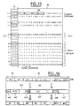
- This principle is schematically figure 8 where is illustrated the comparison principle for the reference time interval 2 and a time length of 6 frames.
- the data frames enter through the input 33 of the compressor 301 which is connected to the input of the first input / output pair of the device 26.
- This input 33 is connected to a buffer 34 of frames ("buffer” in English). ) storing the current frame and operating according to a logic FIFO (of the English "First In First Out”).
- This buffer memory 34 is outputted to a input of a storage memory 35 of the previous frame to the current frame present in the memory 34.
- the memory 34 is also connected to an output of an input block 36 of analysis, which input is connected in the block 36 to a comparison block 361.
- This block 361 is thus intended to compare the current frame with the frame preceding it that it receives on a second input connected to an output of the storage memory 35.
- the analysis block 36 also comprises a state change detection block 362 connected to the output of the comparison block 361 and a state machine 363 connected to the output of the detection block 362 and intended to determine the active or static states of each of the transmitted elements (for example the transmitted doublets), as will be seen below.
- the memory 34 also outputs the current frame to the input of an extractor 37 of active elements, the latter being input connected to the output of the state machine 363 of the analysis block.
- the state machine is connected in parallel with a state encoder 41 intended to provide compact identification codes for the position of the active elements, this being done systematically during operation or on detection of state change. activity of the constituent elements of the frame.
- the memory 34 is connected at the output to the input of a frame synchronization block 38 whose output is connected to the input of a frame counter 39.
- This counter 39 delivers a number specific to the current frame at a first input of a data aggregation block 40 constructing data blocks grouping data specific to the current frame. The number provided by the counter 39 allows identification of the current frame.
- a second input of the grouping block 40 is connected to the output of the extractor 37 while a third input is connected to the output of the encoder 41.
- the grouping block 40 constructs a block of data according to a method which will be detailed hereinafter and supplies the latter to an output buffer 42.
- several blocks are concatenated in this memory 42 before transmission to a physical interface 43 of the output of the compressor 301 ensuring adaptation to the type of interface used for coupling with the transmission modem 31 (Ethernet, IP, or ATM ).
- the codes that are transmitted to block 40 are representative of the state variations of the elements (in this case the doublets) and are a function of the structure of these elements. According to a convention (which can obviously be inverted or modified), a 1 indicates that an element is active, a 0 indicates that an element is static, within a string of bits representing the state of the transmitted elements; for example, for a set of two consecutive time intervals each carrying four doublets, one could have the following combination of codes: 1010 1111 is AF in hexadecimal value. This sequence is representative of six active doublets and two inactive doublets (those assigned code 0). The code indicative of change of state is transmitted without delay, as soon as an element of the frame changes from the static state to the active state.
- a timer is set up for the indications of passage of one or more elements of the active state to the static state.
- the compressor has a preprogrammed 3631 memory of the state machine 363 which has at least three frames (for example) to check the identity of the element considered on the three frames, but in addition the compressor buffer 42 retains at least N frames relative to the previous state change indication; this makes it possible to space the status change signals and avoids overloading the link.
- the state machine is programmed to immediately transmit the state change code of the frame.
- the state change code of the frame comprises all the state codes of the elements carried by the frame, only for the time slots used, these status codes being developed according to the method defined herein. -above.
- the code 00AF delivered by the encoder means that all the elements of the first time interval are static while those of the second time interval are active except the doublets 2 and 4 (example seen above 1010 1111).
- the state change code called the status code in the following, serves as an indication of the location of the active elements of the frame. This status code is provided by the encoder 41 on the status information at the output of the state machine.
- the doublets can therefore have two stable exclusive states, respectively static or active, only the doublets that have been reported as active, are transmitted by the clustering block by adding stuffing bits to complete the data block according to the constraints. of the interface used. These stuffing bits are managed by a manager 401 of internal stuffing bits in the grouping block. These stuffing bits will be explained in more detail later. Note that instead of unnecessary stuffing information, it is possible to use this space of the frame to repeat critical data for the effective rendering of the frames, such as the status code or the frame number. .
- Block 44 comprises a block 441 of compressed data comprising the doublets to be transmitted, a status code of the current frame, for example 00AF. This status code is representative of the position of the active elements within the frame considered.
- the compressor adds by the encoder 41 or the block 40, to the code of state of the current frame, for example 00AF, a specific code 443 signaling the presence of a status code 442 within the block, which means that the transmitted data block corresponds to a case of change of state.
- a specific code 443 signaling the presence of a status code 442 within the block, which means that the transmitted data block corresponds to a case of change of state.
- the decompressor detects the addition of the status code by analyzing the length of the received data block. As soon as the block has a different length, the decompressor is able to deduce that a status code is present at the end of the block.
- a frame number 444 is added at the head of the compressed data block, intended to guarantee the synchronization of the decompression of the data and the taking into account of cases of data block losses in the transmission chain.
- This frame number is counted modulo the capacity of the counter used for this purpose (8 bits or 16 bits for example).
- the data block thus formed is encapsulated in the Ethernet frame, the IP packet, or the ATM cell, depending on the transmission mode adopted.
- the buffer 42 Preferably, several blocks are concatenated in the buffer 42 before encapsulation in order to reduce the encapsulation related overhead.
- the physical interface 43 output adapts to the type of interface used for coupling with the transmission modem (Ethernet, IP, ATM).
- IP protocol with respect to Ethernet makes it possible to include optimized routing and automatic rerouting functions in the event of a link fault.
- the compressor Since the compressor is connected to a satellite transmission system that integrates a DAMA function, the allocation of satellite resources is done slowly, for example every 1.6 seconds, whereas during these 1, 6 seconds, a number of interlocutors will pass from silence to speech and that over the same period, there is not necessarily that many who pass the word to silence, which explains the additional margin roughly equal to 50% between the allocation of channels by the system to the station of traffic considered and the channels actually used on them.
- the system of allocation of As resources do not generally allow the automatic recognition of a margin the compressor adds margin bits intended to simulate an occupation of transmission resources in excess of its actual needs. The additional bits not used for the transmission of useful data are used for the most critical information redundancy purposes, for example, status code or frame number.
- the decompression device uses the margin bits to transmit them to the detriment of the transmission of redundant information, the status code making it possible to signal which new elements are active.
- This process based on the use of significant margin bits makes it possible to smooth the load of the link used and thus to adapt the compression / decompression device according to the invention of the priority request to the inertia that the mechanism of allocation of resources used conventionally, while avoiding transmitting bits without any utility. It should be noted that the shorter the resource allocation cycle, the lower this margin can be.
- an advantageous solution is to multiplex this redundant information on several consecutive data blocks, by spacing the cyclic repetitions of this information by a repeat boundary indicator, and considering that the multiplexed information applies to the block carrying the repeat boundary indicator.
- the role of the DAMA functionality is to ensure a dynamic sharing of the allocated band according to the current needs of each station, considering N stations with balanced current traffic, for the sake of simplification, with 16 communications on each station, one benefits from a considerable statistical multiplexing gain, if N is quite high (at least 10).
- N 1, the resources reserved for the 16 calls are strictly equal to the passage of 16 calls, ie 16 x 16 kbits / s (a call requiring 16 kbits / s at the A-bis interface).
- N high greater than 10
- the ideal case is approached, which corresponds to the theoretical adequacy of the reservation of 50% of the total band for a station, ie 8 x 16 kbps per station, or still for the entirety of the 10 stations 10 x 8 x 16 kbps for a given direction, this quantity being to double for both directions.
- the function of detecting the activity of the doublets is used to inform the resource management center 10 of the current needs of the stations.
- the resource center artificially increases the size of the transmitted packets by adding additional bits within each transmitted packet so as to have a sufficient margin of resources.
- the transmission modem used for the transmission saturates, and rejects the excess packets that it can not transmit with respect to the transmission capacity. which has been allocated for the current cycle.
- the repetition of the status code may be very relevant insofar as the loss or bad reception of the status code by the destination equipment could lead to a disruption of the process of reconstruction of the frame, which would result in a shift of the doublets within the reconstructed frame.
- Level 1 compression completes the first by using identical signaling, exploiting a state code analogous to the state code described for Level 1. It operates by identifying the type of content conveyed by the transmission channel considered. Each call is time-multiplexed at the rate of one doublet per frame for a 16 kbps compressed channel. This time multiplexing is itself structured in frames, for example frames of 320 bits every 20 ms. During the duration of a call, an interlocutor is alternately active or silent. In a non-specific manner to the device under consideration, during periods of silence, the transmission of the frames is maintained but an indicator within the frame makes it possible to indicate that this frame is not active.
- Level 2 compression uses this flag to suspend the transmission of compressed voice data and to transmit only the useful elements of the 320-bit frame.
- the bit corresponding to the position of the element considered in the input frame of the compression device is active within the state code level 2, and then as soon as this useful information has have been transmitted, the bit is reset to the idle state. This process makes it possible to increase the efficiency of the level 1 compression device by extending it by interpretation of non-static elements but having non-useful data.
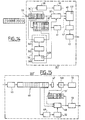
- the figure 11 illustrates in detail a decompression device or decompressor 302 according to an embodiment of the invention of the priority request.
- An input connected to the receiving modem 31 is connected to a physical interface 45 which adapts the frames (Ethernet, IP, or ATM) to the format of the compressed data blocks according to the exposed compression method.
- frames Ethernet, IP, or ATM
- This interface 45 is connected to the output at the input of a FIFO buffer register 46 storing the received data blocks.
- a first output of the register 46 is linked to an extractor 47 of frame number 444 while a second output is connected to a means 48 for inserting the active elements of the current frame and a third output of the register 46 is connected to a state code detector 49.
- a counter 50 of frames internal to the decompressor is initialized at the establishment of the link, with a negative offset with respect to the number of the received frame. This provision is intended to prevent famine cases due to a delay of frames received with respect to the value of the meter.
- a comparator 501 compares the value of the frame number in the extractor 47 and the counter 50. When there is an identity between the value of the counter and the frame number associated with the block present in the buffer register 46, the comparator a memory 51 containing the previous frame to deliver it to an input of the insertion means 48.
- the state code detector 49 detects the status code associated with the received data block and supplies it to the input of a state register 52 whose output is connected to another input of the means 48. insertion.
- the memory register 46 delivers the received data block to a third input of the insertion means 48.
- the insertion means 48 reconstructs the current frame from the repetition of the previous frame of the memory 51 and by replacing the elements indicated as active with the values contained in the block of data received, and on the basis of the information signaling the positions of the active elements delivered by the state register 52.
- the reconstituted frame is then delivered to a physical interface 53 ensuring the adaptation of the data blocks to the format of the frames conveyed on the interface A-bis.
- An example is the encapsulation of a 9.6 kbit / s user voice channel in a 16 kbit frame, encapsulation performed by adding synchronization, stuffing and signaling bits.
- the additional compression method is intended to delete the synchronization and stuffing bits, and to keep only the signaling bits (status codes, 7) which present a dynamic character, as previously defined by the detection of the active elements.
- Synchronization of the return of original frames is done implicitly, by detecting the boundary between the transmitted data blocks.
- the threshold is intended to prevent unwanted switching from the compressed mode to the uncompressed mode, especially when the load of the frames to be transmitted is close to saturation.
- IBS Intelsat Business Services
- IBS modems do not integrate functionality to dynamically vary the rate N x 64 kbps depending on the content to be transmitted.
- the compression device 30 splits the traffic on two or more of its outputs, each output offering a fixed rate, activated according to the load resulting after compression by the compressor 301 according to the method described above.
- the compressed bit rate exceeds the rate reserved on the first channel, for example 5 x 64 kbit / s
- a portion of the traffic is discharged on a second channel, for example at 2 x 64 kbit / s, and as soon as this second channel is in turn saturated, we switch the second channel on a third way to, for example, 4 x 64 kbps, and so on by switching the extra traffic between channels 2 and 3 without interruption of transmission but unloading the traffic from the permanent lane to the additional lane thus formed.
- the original frames are reconstructed by concatenating the data blocks received via the main channel and via the additional channel.
- the figure 12 illustrates a variant 303 of the decompression device 302 of the figure 11 which can be applied equally and advantageously in any IP network, public or private.
- the advantageous functions in this case are: the compression / decompression of data at levels 1 and 2, the addition of the frame number, the decompression with resynchronization of the frames at the output and specific processing in case of non-reception of the compressed frame at the moment when it must be returned.
- the data blocks 44 enter the decompressor 303 via an input 3030.
- a frame number extractor 304 extracts the numbers of each frame to identify them.
- blocks 44 are provided to a memory (305) for storing the data blocks.
- data blocks characterized by their numbers 444 of frames each represented by a solid block are illustrated.
- the first box of each block represents the status code 442 of the block and the following boxes correspond to the compressed data 441.
- a broken line referenced A on the figure 12 surrounds in particular the common part with the figure 11 for the restitution of the original frames. This one having already been described and explained, we will not come back to it here.
- the device 303 comprises a counter initialization circuit 307 receiving the number of the current frame as well as the number of data blocks stored in the memory 305.
- the circuit 307 Upon initialization of the decompression device, the circuit 307 initializes the counter 50 by synchronizing it with the first frame number received by the decompressor.
- the decompressed frames are intended to be kept in the memory 305 of the decompression device as long as the frame number which is respectively associated with them is not identical to the frame number delivered by the local frame counter given a negative offset, to allow a certain flexibility in the return of the frames and to compensate for the temporal fluctuations induced by the transmission system, which often happens during a transmission by satellite or in terrestrial networks including IP, then that the frames are supposed to be restored at a constant and immutable rate.
- the identity occurs at the comparator 501, the frame for which the identity appeared is then applied to the output of the decompression device.
- the previous frame is repeated and / or an error code is generated by a frame absence signaling generator 307 destined for a frame. unrepresented center of management of the telecommunications system.
- the local frame counter is resynchronized on the received frame identifiers.
- the negative offset applied to the output of the frame counter is intended to establish a margin to cover the range of time fluctuations induced by the satellite transmission system.
- a buffer memory is used, making it possible to reorder the received data blocks, on the basis of the block number associated with each block of data, the number represented in the solid boxes, the initialization circuit making it possible to initialize the counter at startup , or whenever a repeated sequence break occurs.
- the initialization of the local counter is performed according to the statistics of variation of the number of blocks present in the buffer, by regulating the minimum value so that it is always greater than 1 taking into account an additional margin, and less than buffer capacity expressed in maximum number of blocks.
- This decompression device therefore has the advantage of being able, on the one hand, to receive data blocks in disordered sequence thanks to the memory 305, and on the other hand to be able to withstand transmission delay fluctuations thanks to the offset. introduced.
- the first two channels of the analysis window 70 are repeated with a period of 4 consecutive frames, identical to the reference pattern 71 constituted by the state of the channel during the last 4 frames preceding the window 70. current analysis. A copression decision of the repeated pattern is then taken.
- the device 301 'of compression according to the invention, illustrated on the figure 14 is analogous to that 301 of the figure 7 , with the exception of a memory 34 'for storing L * N current frames forming the analysis window 70 and a memory 35' for storing the N frames preceding the analysis window forming the reference pattern.
- the device 302 'of the figure 15 is analogous to that of the figure 11 , except for the replacement of the memory 51 by a memory 51 'for storing the reference pattern (the last 4 frames of data preceding the current compressed frame).
- a problem can occur due to a serialization or sequencing defect resulting in an offset of the transmitted data, on the right if channels declared not active were inserted by mistake, on the left if declared active channels have not been inserted.
- the figure 16 represents a structure 44 'of a frame compressed according to the compression method of the invention from a set 500 of NT frames E1 and which regenerates at the end of the chain, on the decompressor side, the NT frames E1:
- This structure conventionally starts with at least one synchronization bit 446 and ends with stuffing bits 447.
- the number of bits of the field 441 ' is equal to the number of bits at 1 in the status code, characterizing the position of the active channels within the input frame, multiplied by the number NT of frames entering the analysis window.
- the device compares the 8 bits of the received frame, located 80 bits after the end of ACD CRC 445; if no formatting or transmission error has occurred, the field thus obtained is equal to the value established for a delimiter 448 arranged just after the CAC.
- the delimiter that sets the boundary between the "concatenated active channels" field and the stuffing bits can be shifted to the position it is supposed to occupy.
- the delimiter has a fixed value, established on the side of the compressor, and equal to 1111 0000 for example.
Landscapes
- Engineering & Computer Science (AREA)
- Computer Networks & Wireless Communication (AREA)
- Signal Processing (AREA)
- Quality & Reliability (AREA)
- Physics & Mathematics (AREA)
- Astronomy & Astrophysics (AREA)
- Aviation & Aerospace Engineering (AREA)
- General Physics & Mathematics (AREA)
- Mobile Radio Communication Systems (AREA)
- Radio Relay Systems (AREA)
- Data Exchanges In Wide-Area Networks (AREA)
- Time-Division Multiplex Systems (AREA)
Claims (20)
- Datenkompressionsvorrichtung (301') zum Komprimieren eines Satzes (500) von aktuellen Datenrahmen (60) eines Datenstroms, wobei diese Rahmen eine gemäß einer Mehrzahl von Zeitabständen definierte Struktur aufweisen, wobei eine erste Gruppe von Zeitabständen derart gewählt wird, dass ein jeder Zeitabstand gemäß einer Mehrzahl von Informationsbits, welche jeweils einen Kommunikationskanal tragen, zerlegt wird, dadurch gekennzeichnet, dass die besagte Kompressionsvorrichtung umfasst:- Mittel (40) zum Übertragen eines Referenzmusters, welches die N Rahmen, die dem Satz (500) von aktuellen Rahmen vorangehen, enthält, wobei N eine ganze Zahl von höher als 1 ist,- Mittel (36, 361, 362, 363) zum Analysieren des aktiven oder statischen Zustands mindestens eines in einem Analysefenster (70) der aktuellen Rahmen (60) enthaltenen Kanals, wobei diesem Kanal der aktive bzw. der statische Zustand zugewiesen wird, wenn der Vergleich des Inhalts dieses Kanals in den N Bits, verglichen zwischen den N Rahmen eines Referenzmusters (71), mit den entsprechenden N Bits der N Rahmen des Analysefensters eine Abweichung des Inhalts für mindestens eines der Bits beziehungsweise eine Stabilität des Inhalts für die Gesamtheit der N Bits ergibt,- Mittel (37, CAC) zum Extrahieren des Inhalts aus den aktiven Kanälen des Analysefensters in Abhängigkeit von den aktiven Zuständen der von den besagten Analysemitteln gelieferten Bits,- Ortungsmittel (41, ACD), ausgelegt für das Bereitstellen der Ortungsangaben der besagten aktiven und statischen Bits in dem aktuellen Rahmen in Abhängigkeit von dem aktiven oder statischen Zustand der von den besagten Analysemittel gelieferten Bits,- Mittel (40) zum Zusammenfügen mindestens einer Kennung des aktuellen Blocks, des Inhalts der aktiven Bits und deren jeweiliger Ortung innerhalb eines auszusendenden Datenblocks (44).
- Vorrichtung nach Anspruch 1, dadurch gekennzeichnet, dass sie erste Mittel (34') zum Speichern der dem aktuellen Analysefenster vorangehenden N Rahmen, welche das Referenzmuster bilden, umfasst.
- Vorrichtung nach Anspruch 1 oder 2, dadurch gekennzeichnet, dass es zweite Mittel (35') zum Speichern der aktuellen Rahmen (60), welche das Analysefenster bilden, umfasst.
- Vorrichtung nach einem der Ansprüche 1 bis 3, dadurch gekennzeichnet, dass das Analysefenster eine Länge von L*N Rahmen aufweist, mit L ≥ 1, so dass die Bits in Blöcke (700) von N Bits zusammengefügt werden und dementsprechend L Blöcke mit N Bits bilden, und dass für jedes räumlich entsprechendes Bit innerhalb der aufeinanderfolgenden L Blöcke die Wiederholung derselben Inhalte eine Entscheidung der Inaktivität des Blocks von N Bits zur Folge hat.
- Vorrichtung nach einem der Ansprüche 1 bis 4, dadurch gekennzeichnet, dass es Mittel (39) zum Identifizieren von Rahmen umfasst, um eine einem jeden komprimierten Rahmen eigene Kennung (444) bereitzustellen.
- Vorrichtung nach einem der vorstehenden Ansprüche, dadurch gekennzeichnet, dass die besagten Ortungsmittel Mittel (41) zum Erzeugen eines Zustandscodes, welcher für die jeweiligen Zustände der besagten Bits der Eingangsrahmen bezeichnend ist, umfassen.
- Vorrichtung nach einem der Ansprüche 1 bis 6, dadurch gekennzeichnet, dass die besagten Analysemittel (36, 361, 362, 363) Mittel (361) zum Vergleichen des Inhalts des Analysemittels mit dem Inhalt des Referenzmusters, Mittel (362) zum Erkennen der Zustandsabweichungen in Abhängigkeit von dem besagten Vergleich und Mittel (363) zum Bestimmen des aktiven oder statischen Zustands eines jeden Bits beziehungsweise der Blöcke von N Bits umfassen.
- Vorrichtung nach Anspruch 7 in Verbindung mit Anspruch 4, dadurch gekennzeichnet, dass die Mittel (363) zum Bestimmen dritte Speichermittel (3631) zum Speichern einer Anzahl L, welche der Anzahl der Bitblöcke mit einer Breite N entspricht, die zu berücksichtigen sind, bevor ein Block als von dem aktiven Zustand in den statischen Zustand übergehend identifiziert wird, umfassen.
- Vorrichtung nach einem der Ansprüche 1 bis 8, dadurch gekennzeichnet, dass sie vierte Speichermittel (42) zum Speichern mehrerer Datenblöcke (44), bevor eine erneute Übertragung vorgenommen wird, umfasst.
- Vorrichtung nach einem der Ansprüche 1 bis 9, dadurch gekennzeichnet, dass die besagten Mittel zum Zusammenfügen eine Fülldatenverwaltungseinrichtung (401) umfassen, welche für die Verwaltung der zusätzlich zu den in der ersten Gruppe von Zeitabständen enthaltenen Daten in dem Block (44) zu übertragenden Daten ausgelegt ist.
- Vorrichtung nach einem der Ansprüche 1 bis 10, dadurch gekennzeichnet, dass sie eine Mehrzahl von Ausgängen für das Senden der Datenblöcke (44) umfasst, wobei jeder Ausgang eine vorgegebene Datenrate bietet, wobei die Vorrichtung derart vorprogrammiert ist, dass die Datenblöcke entsprechend dem jeweiligen Sättigungsgrad der Datenrate selektiv an die Ausgänge geleitet werden.
- Vorrichtung nach Anspruch 11, dadurch gekennzeichnet, dass sie einen ersten Ausgang mit einer fest vorgegebenen Datenrate und einen Ausgang mit variabler Datenrate für den Empfang des Datenblocks umfasst.
- Vorrichtung nach Anspruch 11, dadurch gekennzeichnet, dass sie mindestens drei Ausgänge, einen ersten mit einer fest vorgegebenen Datenrate, einen zweiten mit einer fest vorgegebenen Datenrate, welcher aktiviert wird, sobald die Datenrate die auf dem ersten Ausgang gebotene Kapazität überschreitet, und einen dritten Ausgang, welcher anstelle des zweiten Ausgangs aktiviert wird, sobald die auf dem ersten und auf dem zweiten Ausgang verfügbare Kapazität wiederum nicht ausreichend scheint, umfasst, wobei es die alternative Aktivierung des ersten und des zweiten Ausgangs ermöglicht, die einer Verbindung, an welche Kompressionsvorrichtung angebunden ist, in Abhängigkeit vom aktuellen Bedarf zugeteilte Kapazität in vorgegebenen Schritten zu erhöhen beziehungsweise zu verringern.
- Datendekompressionsvorrichtung zum Dekomprimieren eines komprimierten Datenblocks (44'), wobei der besagte Datenblock eine Gruppe (441') von ausgehend von einem Satz (500) von aktuellen Datenrahmen (60), die eine gemäß einer Mehrzahl von Zeitabständen definierte Struktur aufweisen, komprimierten Daten enthält, wobei eine erste Gruppe von Zeitabständen derart gewählt wird, dass ein jeder Zeitabstand gemäß einer Mehrzahl von Bits, welche jeweils einen Kommunikationskanal tragen, zerlegt wird, dadurch gekennzeichnet, dass sie Mittel (51') für die Speicherung eines empfangenen Referenzmusters, welches die N Rahmen enthält, die dem aktuellen Block von komprimierten Daten vorangehen, wobei N größer als 1 ist, umfasst,
und mit der Maßgabe, dass diesem Kanal der aktive Zustand, beziehungsweise der statische Zustand, zugewiesen wird, wenn der Vergleich des Inhalts dieses Kanals in den N Bits, verglichen zwischen den N Rahmen des Referenzmusters (71), mit den entsprechenden N Bits der N Rahmen des Analysefensters eine Abweichung des Inhalts für mindestens eines der Bits, beziehungsweise eine Stabilität des Inhalts für die Gesamtheit der N Bits ergibt, wobei die Dekompressionsvorrichtung umfasst:- Mittel (49) zum Erkennen von Ortungsangaben der aktiven Bits der Datengruppe (441') in einer Datengruppe (441') des Blocks (44'),- fünfte Mittel (52) zum Speichern der besagten Ortungsangaben der aktiven Elemente,- Mittel (48) zum Einfügen der erkannten statischen und aktiven Bits in Abhängigkeit von der jeweils angegebenen Ortung, um die aktuellen Rahmen wieder herzustellen. - Verfahren zur Verwaltung von Bandbreitenressourcen in einem Telekommunikationssystem zwischen Verkehrsstationen, welche Datenblöcke (44') über eine Satellitenverbindung übertragen, wobei ein solcher Datenblock eine Gruppe (441') von ausgehend von einem Satz von Datenrahmen (60), die eine gemäß einer Mehrzahl von Zeitabständen definierte Struktur aufweisen, komprimierten Daten enthält, wobei eine erste Gruppe von Zeitabständen derart gewählt wird, dass ein jeder der Zeitabstände gemäß einer Mehrzahl von Informationsbits, welche jeweils einen Kommunikationskanal tragen, zerlegt wird, und wobei das besagte System eine Zentrale (10) zur Verwaltung der besagten Ressourcen umfasst,
dadurch gekennzeichnet, dass das Verfahren innerhalb mindestens einer Station umfasst:- Einen Schritt der Analyse des aktiven oder statischen Zustands von in einem Analysefenster (70) der aktuellen Rahmen (60) enthaltenen N Bits, wobei N größer als 1 ist, wobei diesem Kanal der aktive bzw. der statische Zustand zugewiesen wird, wenn der Vergleich des Inhalts dieses Kanals in den N Bits, verglichen zwischen den N Rahmen eines Referenzmusters (71), mit den entsprechenden N Bits der N Rahmen des Analysefensters eine Abweichung des Inhalts für mindestens eines der Bits beziehungsweise eine Stabilität des Inhalts für die Gesamtheit der N Bits ergibt, und wobei das Verfahren auf Ebene der Verwaltungszentrale umfasst:- Einen Schritt des Empfangens einer Information, welche für die analysierten aktiven Kanäle mindestens eines Datenblocks (44') repräsentativ ist;- einen Schritt des Zuordnens von Ressourcen für die Station in Abhängigkeit von der besagten Information. - Verfahren zur Verwaltung von Ressourcen nach Anspruch 15, dadurch gekennzeichnet, dass die übertragene, für die aktiven Bits repräsentative Information aus einer Ressourcenanforderung der besagten mindestens einen Station an die Verwaltungszentrale stammt, die verursachen soll, dass die Übertragungsressourcen der Station variiert, sobald ein Bit vom aktiven Zustand in den statischen Zustand übergeht, oder umgekehrt.
- Verfahren zur Verwaltung von Ressourcen nach Anspruch 15, dadurch gekennzeichnet, dass der Schritt des Empfangens der Information, welche für die analysierten aktiven Bits repräsentativ ist, im Anschluss an einen Schritt des Erkennens der aktiven Bits auf der Übertragungsstrecke der Station im System erfolgt.
- Verfahren zur Verwaltung von Ressourcen nach einem der Ansprüche 15 bis 17, dadurch gekennzeichnet, dass der Schritt Zuordnens von Ressourcen darin besteht, eine Größe von Datenblöcken und/oder eine der Station zugeteilte Übertragungsperiode, welche von der besagten Information abhängt, zu bestimmen, um eine Übertragung zumindest der aktiven Bits zu ermöglichen.
- Verfahren zur Verwaltung von Ressourcen nach einem der Ansprüche 15 bis 18, dadurch gekennzeichnet, dass der Schritt des Zuordnens von Ressourcen für die Station in Abhängigkeit von der besagten Information, gemäß welcher eine zusätzliche Reserve zwischen der Anzahl von aktiven Bits und der Dimensionierung der einer jeden Verbindung der Stationen des Systems zugeordneten Ressourcen zweckmäßig berücksichtigt wird, erfolgt.
- Verfahren zur Verwaltung von Ressourcen nach einem der Ansprüche 15 bis 19, dadurch gekennzeichnet, dass das besagte System einen Ergänzungsdaten-Manager (401) umfasst, welcher dazu ausgelegt ist, auf der für die besagte mindestens eine Station aufgebauten Verbindung Ergänzungsdaten hinzuzufügen, so dass eine Ressourcenreserve gewährleistet wird.
Applications Claiming Priority (3)
| Application Number | Priority Date | Filing Date | Title |
|---|---|---|---|
| FR0111048 | 2001-08-23 | ||
| FR0111048A FR2828979A1 (fr) | 2001-08-23 | 2001-08-23 | Compresseur, decompresseur, bloc de donnees et procede de gestion de ressources |
| PCT/FR2002/002252 WO2003019834A1 (fr) | 2001-08-23 | 2002-06-28 | Compresseur, decompresseur, bloc de donnees et procede de gestion de ressources |
Publications (2)
| Publication Number | Publication Date |
|---|---|
| EP1421723A1 EP1421723A1 (de) | 2004-05-26 |
| EP1421723B1 true EP1421723B1 (de) | 2012-03-14 |
Family
ID=8866686
Family Applications (1)
| Application Number | Title | Priority Date | Filing Date |
|---|---|---|---|
| EP02796286A Expired - Lifetime EP1421723B1 (de) | 2001-08-23 | 2002-06-28 | Kompressor, dekompressor und ressourcenverwaltungsverfahren |
Country Status (5)
| Country | Link |
|---|---|
| US (1) | US20050117610A1 (de) |
| EP (1) | EP1421723B1 (de) |
| AT (1) | ATE549809T1 (de) |
| FR (1) | FR2828979A1 (de) |
| WO (1) | WO2003019834A1 (de) |
Families Citing this family (13)
| Publication number | Priority date | Publication date | Assignee | Title |
|---|---|---|---|---|
| FR2841726B1 (fr) * | 2002-06-28 | 2005-04-29 | Cit Alcatel | Methode de decision securisee d'un etat de donnee d'un canal de communication pour systeme de transmission |
| FR2863797B1 (fr) * | 2003-12-15 | 2006-02-24 | Cit Alcatel | Compression/decompression de couche deux pour la transmission mixte synchrone/asynchrone de trames de donnees au sein d'un reseau de communications |
| KR100825737B1 (ko) * | 2005-10-11 | 2008-04-29 | 한국전자통신연구원 | 스케일러블 비디오 코딩 방법 및 그 코딩 방법을 이용하는코덱 |
| GB0522987D0 (en) * | 2005-11-10 | 2005-12-21 | Cambridge Broadband Ltd | Communication system |
| DE212007000072U1 (de) * | 2006-08-15 | 2009-06-18 | Celtro Ltd. | System zur Brandbreiteneinsparung während einer Broadcast-/Multicast-Übertragung |
| US8031604B2 (en) * | 2006-10-25 | 2011-10-04 | Sydir Jaroslaw J | Algorithm for grouping stations for transmission in a multi-phase frame structure to support multi-hop wireless broadband access communications |
| FR2913292B1 (fr) * | 2007-03-01 | 2009-04-10 | Alcatel Lucent Sas | Station centrale a gestion simplifiee d'allocation de ressources, pour un reseau de communication radio utilisant un reseau de transport |
| JP2009225260A (ja) * | 2008-03-18 | 2009-10-01 | Fujitsu Ten Ltd | 制御装置、制御方法、車両の制御装置、及び車両の制御システム |
| US8179792B1 (en) * | 2008-06-06 | 2012-05-15 | Sprint Communications Company L.P. | Packet de-duplication |
| WO2010083936A1 (en) * | 2009-01-23 | 2010-07-29 | Nortel Networks Limited | Method for packet communication |
| DE102009012164A1 (de) * | 2009-03-06 | 2010-09-09 | Siemens Aktiengesellschaft | Verfahren zur Auswahl eines einem Übertragungsnetz eines Automatisierungs-Systems zugeordneten Kommunikationssystems |
| US9922037B2 (en) | 2015-01-30 | 2018-03-20 | Splunk Inc. | Index time, delimiter based extractions and previewing for use in indexing |
| GB2557628B (en) | 2016-12-13 | 2020-01-01 | Inmarsat Global Ltd | Forward link power control |
Family Cites Families (8)
| Publication number | Priority date | Publication date | Assignee | Title |
|---|---|---|---|---|
| CA977476A (en) * | 1971-04-15 | 1975-11-04 | Giancarlo Monti | Digital voice interpolation system for pcm systems |
| CA995360A (en) * | 1971-04-30 | 1976-08-17 | Rene Costales | Speech predictive encoding communication system |
| US3927268A (en) * | 1971-04-30 | 1975-12-16 | Communications Satellite Corp | Speech predictive encoding communication system |
| US3811014A (en) * | 1973-03-12 | 1974-05-14 | Logicon Inc | Adaptive pulse code modulation system |
| US4418409A (en) * | 1980-03-07 | 1983-11-29 | Ibm Corporation | Byte data activity compression |
| US4592050A (en) * | 1984-03-29 | 1986-05-27 | International Business Machines Corporation | Apparatus and method for providing a transparent interface across a satellite communications link |
| US6144658A (en) * | 1996-12-20 | 2000-11-07 | Cisco Technology, Inc. | Repetitive pattern removal in a voice channel of a communication network |
| US6529512B1 (en) * | 1997-07-15 | 2003-03-04 | International Business Machines Corporation | Statistical method of data compression and decompression |
-
2001
- 2001-08-23 FR FR0111048A patent/FR2828979A1/fr active Pending
-
2002
- 2002-06-28 EP EP02796286A patent/EP1421723B1/de not_active Expired - Lifetime
- 2002-06-28 AT AT02796286T patent/ATE549809T1/de active
- 2002-06-28 US US10/487,272 patent/US20050117610A1/en not_active Abandoned
- 2002-06-28 WO PCT/FR2002/002252 patent/WO2003019834A1/fr not_active Ceased
Also Published As
| Publication number | Publication date |
|---|---|
| FR2828979A1 (fr) | 2003-02-28 |
| ATE549809T1 (de) | 2012-03-15 |
| US20050117610A1 (en) | 2005-06-02 |
| EP1421723A1 (de) | 2004-05-26 |
| WO2003019834A1 (fr) | 2003-03-06 |
Similar Documents
| Publication | Publication Date | Title |
|---|---|---|
| FR2842683A1 (fr) | Dispositif de multiplexage, dispositif de multiplexage et systeme de multiplexage/demultiplexage | |
| EP0104991B1 (de) | Lokales hybrides Nachrichtennetz in Durchschalte- und Paketvermittlungsbetrieb mit einer Zeitmultiplex-Ringleitung | |
| RU2187205C2 (ru) | Устройство и способ передачи пакетных речевых данных в системе мобильной связи | |
| EP0162173B1 (de) | Digitales Übertragungssystem für Sprachpakete | |
| EP0493176B1 (de) | Vorrichtung zur Übertragung von Signalisierungsdaten in einem asynchronen Netz, insbesondere ATM-Netz, wobei diese Daten kanalweise in einem Multirahmen zusammengefasst und synchron, ausserhalb des Bandes übertragen werden | |
| US7876785B2 (en) | Transport of aggregated client packets | |
| EP0036808B1 (de) | Konzentrator für Kommunikationssystem zum Anschliessen mehrerer asynchroner Telematik-Terminals | |
| EP0487428A1 (de) | Anordnung für synchrone Informationsübertragung über ein asynchrones Netzwerk, insbesondere über ein ATM-Netzwerk | |
| FR2505114A1 (fr) | Systeme de traitement de donnees video de television | |
| WO2003019834A1 (fr) | Compresseur, decompresseur, bloc de donnees et procede de gestion de ressources | |
| EP0559593A1 (de) | Verfahren und Vorrichtung zur Datenkompression und -dekompression für eine Übertragungsanordnung | |
| FR2570234A1 (fr) | Procede de transmission de donnees par interface et dispositif de liaison par interface pour la mise en oeuvre de ce procede | |
| EP1545140B1 (de) | Schicht-ZweiI Kompression/Dekompression in einem zellularen Kommunikationsnetz | |
| CA2525276C (fr) | Gestion de ressources d'un reseau de communications de type point a multipoint ou multipoint a multipoint, par deux niveaux d'allocation | |
| EP0987917A1 (de) | Verfahren zur Zellulären Datenkommunikation, Zell, Kommunikationssystem und Netz-Endgerät | |
| EP1545032A2 (de) | Verfahren und Vorrichtung zur Synchronisierung von Takten von digitalen Kodierern und Dekodierern | |
| EP1376958B1 (de) | Verfahren zur sicheren Entscheidung eines gegebenen Zustandes von einem Kommunikationskanal für ein Übertragungssystem | |
| US7391760B1 (en) | Method and apparatus for efficient protocol-independent trunking of data signals | |
| CA2252818C (en) | Minicell decoupling | |
| FR2833118A1 (fr) | Procede d'estimation de performance lors de la fourniture de services de donnees intolerants vis-a vis des retards | |
| EP0648063A1 (de) | Methode und Anlage für die Transmission von Sätzen von ATM-Zellen | |
| US20100284425A1 (en) | System and method of using tdm variable frame lengths in a telecommunications network | |
| EP1972110B1 (de) | Implizite reservierung von ressourcen in einem punkt-zu-multipunkt- oder multipunkt-zu-multipunkt-kommunikationsnetzwerk | |
| WO2023156579A1 (fr) | Procédés et dispositifs de traitement de données montantes pour réseaux optiques passifs en cascade | |
| EP1244329A1 (de) | Verfahren und Vorrichtung zur Übertragung von Daten innerhalb eines eine Übertragungsleitung mit niedriger Datenrate enthaltenden Kommunikationsnetzes |
Legal Events
| Date | Code | Title | Description |
|---|---|---|---|
| PUAI | Public reference made under article 153(3) epc to a published international application that has entered the european phase |
Free format text: ORIGINAL CODE: 0009012 |
|
| 17P | Request for examination filed |
Effective date: 20040323 |
|
| AK | Designated contracting states |
Kind code of ref document: A1 Designated state(s): AT BE CH CY DE DK ES FI FR GB GR IE IT LI LU MC NL PT SE TR |
|
| AX | Request for extension of the european patent |
Extension state: AL LT LV MK RO SI |
|
| RIN1 | Information on inventor provided before grant (corrected) |
Inventor name: FAURE, CECILE Inventor name: FARINEAU, JEAN Inventor name: CHEVALLIER, EMMANUELLE Inventor name: CHUBERRE, NICOLAS |
|
| 17Q | First examination report despatched |
Effective date: 20061013 |
|
| RAP1 | Party data changed (applicant data changed or rights of an application transferred) |
Owner name: ALCATEL LUCENT |
|
| GRAP | Despatch of communication of intention to grant a patent |
Free format text: ORIGINAL CODE: EPIDOSNIGR1 |
|
| RTI1 | Title (correction) |
Free format text: COMPRESSOR, DECOMPRESSOR AND RESOURCE MANAGEMENT METHOD |
|
| RIN1 | Information on inventor provided before grant (corrected) |
Inventor name: CHEVALLIER, EMMANUELLE Inventor name: FAURE, CECILE Inventor name: FARINEAU, JEAN Inventor name: CHUBERRE, NICOLAS |
|
| GRAS | Grant fee paid |
Free format text: ORIGINAL CODE: EPIDOSNIGR3 |
|
| GRAA | (expected) grant |
Free format text: ORIGINAL CODE: 0009210 |
|
| RAP1 | Party data changed (applicant data changed or rights of an application transferred) |
Owner name: ALCATEL LUCENT |
|
| AK | Designated contracting states |
Kind code of ref document: B1 Designated state(s): AT BE CH CY DE DK ES FI FR GB GR IE IT LI LU MC NL PT SE TR |
|
| REG | Reference to a national code |
Ref country code: GB Ref legal event code: FG4D Free format text: NOT ENGLISH |
|
| REG | Reference to a national code |
Ref country code: AT Ref legal event code: REF Ref document number: 549809 Country of ref document: AT Kind code of ref document: T Effective date: 20120315 Ref country code: CH Ref legal event code: EP |
|
| REG | Reference to a national code |
Ref country code: IE Ref legal event code: FG4D Free format text: LANGUAGE OF EP DOCUMENT: FRENCH |
|
| REG | Reference to a national code |
Ref country code: DE Ref legal event code: R096 Ref document number: 60242417 Country of ref document: DE Effective date: 20120516 |
|
| REG | Reference to a national code |
Ref country code: NL Ref legal event code: VDEP Effective date: 20120314 |
|
| PG25 | Lapsed in a contracting state [announced via postgrant information from national office to epo] |
Ref country code: GR Free format text: LAPSE BECAUSE OF FAILURE TO SUBMIT A TRANSLATION OF THE DESCRIPTION OR TO PAY THE FEE WITHIN THE PRESCRIBED TIME-LIMIT Effective date: 20120615 Ref country code: FI Free format text: LAPSE BECAUSE OF FAILURE TO SUBMIT A TRANSLATION OF THE DESCRIPTION OR TO PAY THE FEE WITHIN THE PRESCRIBED TIME-LIMIT Effective date: 20120314 |
|
| REG | Reference to a national code |
Ref country code: AT Ref legal event code: MK05 Ref document number: 549809 Country of ref document: AT Kind code of ref document: T Effective date: 20120314 |
|
| PG25 | Lapsed in a contracting state [announced via postgrant information from national office to epo] |
Ref country code: CY Free format text: LAPSE BECAUSE OF FAILURE TO SUBMIT A TRANSLATION OF THE DESCRIPTION OR TO PAY THE FEE WITHIN THE PRESCRIBED TIME-LIMIT Effective date: 20120314 |
|
| PG25 | Lapsed in a contracting state [announced via postgrant information from national office to epo] |
Ref country code: SE Free format text: LAPSE BECAUSE OF FAILURE TO SUBMIT A TRANSLATION OF THE DESCRIPTION OR TO PAY THE FEE WITHIN THE PRESCRIBED TIME-LIMIT Effective date: 20120314 |
|
| PG25 | Lapsed in a contracting state [announced via postgrant information from national office to epo] |
Ref country code: PT Free format text: LAPSE BECAUSE OF FAILURE TO SUBMIT A TRANSLATION OF THE DESCRIPTION OR TO PAY THE FEE WITHIN THE PRESCRIBED TIME-LIMIT Effective date: 20120716 |
|
| BERE | Be: lapsed |
Owner name: ALCATEL LUCENT Effective date: 20120630 |
|
| PLBE | No opposition filed within time limit |
Free format text: ORIGINAL CODE: 0009261 |
|
| STAA | Information on the status of an ep patent application or granted ep patent |
Free format text: STATUS: NO OPPOSITION FILED WITHIN TIME LIMIT |
|
| PG25 | Lapsed in a contracting state [announced via postgrant information from national office to epo] |
Ref country code: AT Free format text: LAPSE BECAUSE OF FAILURE TO SUBMIT A TRANSLATION OF THE DESCRIPTION OR TO PAY THE FEE WITHIN THE PRESCRIBED TIME-LIMIT Effective date: 20120314 Ref country code: MC Free format text: LAPSE BECAUSE OF NON-PAYMENT OF DUE FEES Effective date: 20120630 Ref country code: DK Free format text: LAPSE BECAUSE OF FAILURE TO SUBMIT A TRANSLATION OF THE DESCRIPTION OR TO PAY THE FEE WITHIN THE PRESCRIBED TIME-LIMIT Effective date: 20120314 Ref country code: NL Free format text: LAPSE BECAUSE OF FAILURE TO SUBMIT A TRANSLATION OF THE DESCRIPTION OR TO PAY THE FEE WITHIN THE PRESCRIBED TIME-LIMIT Effective date: 20120314 |
|
| REG | Reference to a national code |
Ref country code: CH Ref legal event code: PL |
|
| REG | Reference to a national code |
Ref country code: CH Ref legal event code: PL |
|
| 26N | No opposition filed |
Effective date: 20121217 |
|
| PG25 | Lapsed in a contracting state [announced via postgrant information from national office to epo] |
Ref country code: IT Free format text: LAPSE BECAUSE OF FAILURE TO SUBMIT A TRANSLATION OF THE DESCRIPTION OR TO PAY THE FEE WITHIN THE PRESCRIBED TIME-LIMIT Effective date: 20120314 |
|
| REG | Reference to a national code |
Ref country code: IE Ref legal event code: MM4A |
|
| REG | Reference to a national code |
Ref country code: DE Ref legal event code: R097 Ref document number: 60242417 Country of ref document: DE Effective date: 20121217 |
|
| PG25 | Lapsed in a contracting state [announced via postgrant information from national office to epo] |
Ref country code: IE Free format text: LAPSE BECAUSE OF NON-PAYMENT OF DUE FEES Effective date: 20120628 Ref country code: LI Free format text: LAPSE BECAUSE OF NON-PAYMENT OF DUE FEES Effective date: 20120630 Ref country code: BE Free format text: LAPSE BECAUSE OF NON-PAYMENT OF DUE FEES Effective date: 20120630 Ref country code: CH Free format text: LAPSE BECAUSE OF NON-PAYMENT OF DUE FEES Effective date: 20120630 Ref country code: ES Free format text: LAPSE BECAUSE OF FAILURE TO SUBMIT A TRANSLATION OF THE DESCRIPTION OR TO PAY THE FEE WITHIN THE PRESCRIBED TIME-LIMIT Effective date: 20120625 |
|
| REG | Reference to a national code |
Ref country code: FR Ref legal event code: GC Effective date: 20131018 |
|
| PG25 | Lapsed in a contracting state [announced via postgrant information from national office to epo] |
Ref country code: TR Free format text: LAPSE BECAUSE OF FAILURE TO SUBMIT A TRANSLATION OF THE DESCRIPTION OR TO PAY THE FEE WITHIN THE PRESCRIBED TIME-LIMIT Effective date: 20120314 |
|
| PG25 | Lapsed in a contracting state [announced via postgrant information from national office to epo] |
Ref country code: LU Free format text: LAPSE BECAUSE OF NON-PAYMENT OF DUE FEES Effective date: 20120628 |
|
| REG | Reference to a national code |
Ref country code: FR Ref legal event code: RG Effective date: 20141016 |
|
| REG | Reference to a national code |
Ref country code: FR Ref legal event code: PLFP Year of fee payment: 14 |
|
| REG | Reference to a national code |
Ref country code: FR Ref legal event code: PLFP Year of fee payment: 15 |
|
| REG | Reference to a national code |
Ref country code: FR Ref legal event code: PLFP Year of fee payment: 16 |
|
| PGFP | Annual fee paid to national office [announced via postgrant information from national office to epo] |
Ref country code: FR Payment date: 20170621 Year of fee payment: 16 |
|
| PGFP | Annual fee paid to national office [announced via postgrant information from national office to epo] |
Ref country code: GB Payment date: 20181228 Year of fee payment: 17 |
|
| PG25 | Lapsed in a contracting state [announced via postgrant information from national office to epo] |
Ref country code: FR Free format text: LAPSE BECAUSE OF NON-PAYMENT OF DUE FEES Effective date: 20180630 |
|
| PGFP | Annual fee paid to national office [announced via postgrant information from national office to epo] |
Ref country code: DE Payment date: 20181228 Year of fee payment: 17 |
|
| REG | Reference to a national code |
Ref country code: GB Ref legal event code: 732E Free format text: REGISTERED BETWEEN 20190429 AND 20190502 |
|
| REG | Reference to a national code |
Ref country code: DE Ref legal event code: R082 Ref document number: 60242417 Country of ref document: DE Representative=s name: MENZIETTI WETZEL, DE Ref country code: DE Ref legal event code: R081 Ref document number: 60242417 Country of ref document: DE Owner name: PROVENANCE ASSET GROUP LLC, PITTSFORD, US Free format text: FORMER OWNER: ALCATEL LUCENT, PARIS, FR |
|
| REG | Reference to a national code |
Ref country code: DE Ref legal event code: R119 Ref document number: 60242417 Country of ref document: DE |
|
| GBPC | Gb: european patent ceased through non-payment of renewal fee |
Effective date: 20190628 |
|
| PG25 | Lapsed in a contracting state [announced via postgrant information from national office to epo] |
Ref country code: GB Free format text: LAPSE BECAUSE OF NON-PAYMENT OF DUE FEES Effective date: 20190628 Ref country code: DE Free format text: LAPSE BECAUSE OF NON-PAYMENT OF DUE FEES Effective date: 20200101 |