EP1422165A2 - Corps creux, en particulier conteneur isolant - Google Patents
Corps creux, en particulier conteneur isolant Download PDFInfo
- Publication number
- EP1422165A2 EP1422165A2 EP03022758A EP03022758A EP1422165A2 EP 1422165 A2 EP1422165 A2 EP 1422165A2 EP 03022758 A EP03022758 A EP 03022758A EP 03022758 A EP03022758 A EP 03022758A EP 1422165 A2 EP1422165 A2 EP 1422165A2
- Authority
- EP
- European Patent Office
- Prior art keywords
- profile
- shell
- hollow body
- shell body
- end edges
- Prior art date
- Legal status (The legal status is an assumption and is not a legal conclusion. Google has not performed a legal analysis and makes no representation as to the accuracy of the status listed.)
- Granted
Links
- 150000001875 compounds Chemical class 0.000 claims abstract description 36
- 238000000034 method Methods 0.000 claims abstract description 25
- 238000005187 foaming Methods 0.000 claims abstract description 21
- 230000001070 adhesive effect Effects 0.000 claims description 8
- 239000000853 adhesive Substances 0.000 claims description 7
- 238000005304 joining Methods 0.000 claims description 5
- 230000007704 transition Effects 0.000 claims description 3
- 239000004831 Hot glue Substances 0.000 claims description 2
- 210000001503 joint Anatomy 0.000 claims description 2
- 230000002093 peripheral effect Effects 0.000 claims description 2
- 229920005830 Polyurethane Foam Polymers 0.000 description 9
- 230000006835 compression Effects 0.000 description 9
- 238000007906 compression Methods 0.000 description 9
- 239000011810 insulating material Substances 0.000 description 9
- 239000011496 polyurethane foam Substances 0.000 description 9
- 238000004519 manufacturing process Methods 0.000 description 6
- 235000013305 food Nutrition 0.000 description 5
- 238000007789 sealing Methods 0.000 description 3
- XRWSZZJLZRKHHD-WVWIJVSJSA-N asunaprevir Chemical compound O=C([C@@H]1C[C@H](CN1C(=O)[C@@H](NC(=O)OC(C)(C)C)C(C)(C)C)OC1=NC=C(C2=CC=C(Cl)C=C21)OC)N[C@]1(C(=O)NS(=O)(=O)C2CC2)C[C@H]1C=C XRWSZZJLZRKHHD-WVWIJVSJSA-N 0.000 description 2
- 238000005253 cladding Methods 0.000 description 2
- 229940125961 compound 24 Drugs 0.000 description 2
- 230000000694 effects Effects 0.000 description 2
- 239000006260 foam Substances 0.000 description 2
- 239000000463 material Substances 0.000 description 2
- 229920003023 plastic Polymers 0.000 description 2
- 239000004033 plastic Substances 0.000 description 2
- 238000003466 welding Methods 0.000 description 2
- 238000004026 adhesive bonding Methods 0.000 description 1
- 230000015572 biosynthetic process Effects 0.000 description 1
- 238000005056 compaction Methods 0.000 description 1
- LYKJEJVAXSGWAJ-UHFFFAOYSA-N compactone Natural products CC1(C)CCCC2(C)C1CC(=O)C3(O)CC(C)(CCC23)C=C LYKJEJVAXSGWAJ-UHFFFAOYSA-N 0.000 description 1
- 239000002131 composite material Substances 0.000 description 1
- 238000001816 cooling Methods 0.000 description 1
- 230000007423 decrease Effects 0.000 description 1
- 230000003247 decreasing effect Effects 0.000 description 1
- 238000005516 engineering process Methods 0.000 description 1
- -1 for example Chemical class 0.000 description 1
- 239000011796 hollow space material Substances 0.000 description 1
- 238000000265 homogenisation Methods 0.000 description 1
- 238000009413 insulation Methods 0.000 description 1
- 230000035484 reaction time Effects 0.000 description 1
- 230000000284 resting effect Effects 0.000 description 1
- 238000003860 storage Methods 0.000 description 1
- 238000009423 ventilation Methods 0.000 description 1
Images

Classifications
-
- A—HUMAN NECESSITIES
- A47—FURNITURE; DOMESTIC ARTICLES OR APPLIANCES; COFFEE MILLS; SPICE MILLS; SUCTION CLEANERS IN GENERAL
- A47J—KITCHEN EQUIPMENT; COFFEE MILLS; SPICE MILLS; APPARATUS FOR MAKING BEVERAGES
- A47J41/00—Thermally-insulated vessels, e.g. flasks, jugs, jars
- A47J41/0055—Constructional details of the elements forming the thermal insulation
- A47J41/0072—Double walled vessels comprising a single insulating layer between inner and outer walls
- A47J41/0077—Double walled vessels comprising a single insulating layer between inner and outer walls made of two vessels inserted in each other
-
- B—PERFORMING OPERATIONS; TRANSPORTING
- B29—WORKING OF PLASTICS; WORKING OF SUBSTANCES IN A PLASTIC STATE IN GENERAL
- B29C—SHAPING OR JOINING OF PLASTICS; SHAPING OF MATERIAL IN A PLASTIC STATE, NOT OTHERWISE PROVIDED FOR; AFTER-TREATMENT OF THE SHAPED PRODUCTS, e.g. REPAIRING
- B29C44/00—Shaping by internal pressure generated in the material, e.g. swelling or foaming ; Producing porous or cellular expanded plastics articles
- B29C44/02—Shaping by internal pressure generated in the material, e.g. swelling or foaming ; Producing porous or cellular expanded plastics articles for articles of definite length, i.e. discrete articles
- B29C44/12—Incorporating or moulding on preformed parts, e.g. inserts or reinforcements
- B29C44/1228—Joining preformed parts by the expanding material
- B29C44/1233—Joining preformed parts by the expanding material the preformed parts being supported during expanding
-
- B—PERFORMING OPERATIONS; TRANSPORTING
- B29—WORKING OF PLASTICS; WORKING OF SUBSTANCES IN A PLASTIC STATE IN GENERAL
- B29C—SHAPING OR JOINING OF PLASTICS; SHAPING OF MATERIAL IN A PLASTIC STATE, NOT OTHERWISE PROVIDED FOR; AFTER-TREATMENT OF THE SHAPED PRODUCTS, e.g. REPAIRING
- B29C44/00—Shaping by internal pressure generated in the material, e.g. swelling or foaming ; Producing porous or cellular expanded plastics articles
- B29C44/34—Auxiliary operations
- B29C44/36—Feeding the material to be shaped
- B29C44/38—Feeding the material to be shaped into a closed space, i.e. to make articles of definite length
- B29C44/385—Feeding the material to be shaped into a closed space, i.e. to make articles of definite length using manifolds or channels directing the flow in the mould
-
- B—PERFORMING OPERATIONS; TRANSPORTING
- B65—CONVEYING; PACKING; STORING; HANDLING THIN OR FILAMENTARY MATERIAL
- B65D—CONTAINERS FOR STORAGE OR TRANSPORT OF ARTICLES OR MATERIALS, e.g. BAGS, BARRELS, BOTTLES, BOXES, CANS, CARTONS, CRATES, DRUMS, JARS, TANKS, HOPPERS, FORWARDING CONTAINERS; ACCESSORIES, CLOSURES, OR FITTINGS THEREFOR; PACKAGING ELEMENTS; PACKAGES
- B65D81/00—Containers, packaging elements, or packages, for contents presenting particular transport or storage problems, or adapted to be used for non-packaging purposes after removal of contents
- B65D81/38—Containers, packaging elements, or packages, for contents presenting particular transport or storage problems, or adapted to be used for non-packaging purposes after removal of contents with thermal insulation
- B65D81/3813—Containers, packaging elements, or packages, for contents presenting particular transport or storage problems, or adapted to be used for non-packaging purposes after removal of contents with thermal insulation rigid container being in the form of a box, tray or like container
- B65D81/3823—Containers, packaging elements, or packages, for contents presenting particular transport or storage problems, or adapted to be used for non-packaging purposes after removal of contents with thermal insulation rigid container being in the form of a box, tray or like container formed of different materials, e.g. laminated or foam filling between walls
Definitions
- the invention relates to a hollow body consisting of a first Shell body and a second shell body, which in Area of their circumferential, adjacent end edges tight are interconnected and enclose a cavity between them, which is foamed with a hardening insulating compound is.
- Hollow bodies of the generic type can be used, for example, as Thermal containers can be designed, as is known from DE 201 09 502 U1 is known. Such thermal containers are usually used for short-term storage and transportation of food.
- a hollow body is trough-shaped and has a double-walled structure.
- a first shell body and a second shell body provided, which in the area of their surrounding, neighboring End edges are tightly connected.
- a thermal insulating compound such as for example, polyurethane foam are foamed.
- Such Insulating compound has the property of increasing during the foaming process expand and the trapped between the shell bodies Completely fill the cavity.
- the two shell bodies manufactured, for example, in the deep-drawing process.
- Plastics are usually used as the material here Question.
- These shell bodies become the before assembly the actual container wall is first inserted into tool holders, in which they are flat with their complete outer contour issue.
- These tool holders have a corresponding one inner shape, which is the outer shape of the two Shell body corresponds.
- these two shell bodies are sealed together connect, various welding or adhesive processes used to connect. Because especially if the Butt end edges of the two shell bodies, such connections between these end edges are difficult without the shell body is to be warped Container known, in which in a region of the longitudinal edges of the container itself these adjacent end edges perpendicular to the outside of the actual container wall stand. These areas lie flat on top of each other, so that this then without significant distortion of the shell body can be welded together.
- connection types are, for example, also from DE 41 33 926 A1 known, in which an insulated container is described which consists of an inner wall and an outer wall, which form the two shell bodies. Even the ones suggested here Connection types always require a further operation, to firmly connect the two shell bodies to each other, whereby the tightness, depending on the type of connection, is only guaranteed to a limited extent is.
- DE 195 41 412 C1 discloses a method for producing a heat-insulating composite profile.
- two rails Connected to one another via insulating webs along their longitudinal edges.
- the insulating webs are in the U-shaped grooves Profile rails inserted. These grooves are after the Inserting the insulating webs pressed so that a clamping connection arises.
- DE 35 37 061 C2 describes a housing for cooling devices, its insulating walls from an inner shell body and parts of an outer lining arranged at a distance from it be formed.
- the inner shell body is with a provided its surrounding flange, parts on the edge the outer cladding can be attached.
- a tight connection between the multi-part outer cladding and the shell body not provided. But if you wanted to achieve one, So here would be additional measures, such as gluing or Welding necessary.
- the object of the invention is a container of the generic type in such a way that this especially tightly manufactured in a single operation can be.
- a dimensionally stable, circumferential profile strip is provided between the adjacent end edges of the two shell bodies, which for receiving the end edges two cross-sectionally U-shaped profile sections, each with an inside has in the cavity and a profile leg lying on the outside of the respective shell body and that the respective inner profile leg in the area of the respective end edge forms an intermediate space together with the respective shell body, which is connected to the hollow space via a narrowed feed gap or a narrowed feed channel, via which insulating material enters the intermediate space during the foaming process and completely fills the intermediate space ,
- This profile bar has two im Cross section of U-shaped profile sections, which for holding one of the end edges of the two shell bodies serves.
- the inner one Profile leg forms in the area of the respective end edge a shell body together with the shell body in the area this end edge a space which is in line with the cavity, which is defined by the stacked shell bodies, via a narrowed feed gap or a narrowed feed channel communicates.
- This means that the inner profile leg not on the respective end edge of the respective shell body is applied, but has a certain distance from it, wherein the intended circumferential feed gap or feed channel in the Comparison to this distance between the respective profile leg is narrowed.
- Insulating compound such as polyurethane foam in the Gap can be supplied so that at the end of the foaming process Space between the inner profile leg and the respective End edge of the respective shell body completely filled is.
- This flow of the insulating compound into the space is caused by an increase in pressure in the cavity of the hollow body causes.
- This pressure increase to approx. 4 to 6 bar takes place at the latest then instead of when the insulating compound due to its expansion reaction the cavity between the shell bodies completely filled in and thus only a further expansion over the feed gap or feed channel in the space between Profile leg and shell body is possible.
- the wall sections of the shell body in Area of their peripheral end edges one in cross section have tapered mounting web with which these End edges of the shell body in each case in the assigned U-shaped Project the profile section of the profile bar.
- the inner Profile legs are wedge-shaped in cross section and extend over the respective height of the assembly web.
- the feed gap becomes approximately in the step-shaped transition area between the assembly web and the remaining wall section of the respective Shell body or its end edge formed.
- this configuration creates a defined feed gap achieved and on the other hand due to the wedge-shaped design of the inner profile leg, the inflow of the insulating material to the parting plane between the two shell bodies towards the outside deflected so that a complete filling of the space is guaranteed.
- the surface structure the profile strip and / or the shell body are formed in this way is that between the outer profile legs and the outer surfaces a capillary gap is formed in the associated wall sections becomes. This configuration enables the insulating compound to be pressed in between the outer profile legs and the shell body favored, so that the sealing effect is improved.
- the profile strip with their a profile section on one of the shell body by a punctually applied adhesive, especially by a Hot glue before joining the shell body together with the profile bar is pre-fixed.
- This configuration will simplifies the manufacture of the hollow body, in particular the desired alignment of the profile strip with respect to the shell bodies ensured.
- each of the tool holders in the area of the end edge of a received shell body is provided with a circumferential recess in which the profile strip is appropriately received during the joining process.
- the wall sections in Area with their end edges and the arranged between them Profile strip form a butt joint and together with the profile section the profile bar in alignment or under one obtuse angles are arranged extending to each other.
- This Design simplifies "stacking" in particular of the two shell bodies.
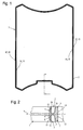
- Fig. 1 shows a profile strip 1 of the type according to the invention, which, as can be seen in particular from Figure 2, two U-shaped trained profile sections 2 and 3.
- This both profile sections 2 and 3 are in the present embodiment the profile strip 1 opposite each other in mirror symmetry, so that the upper in Fig. 2 profile section 2 and the lower profile section 3 is open at the bottom.
- This Profile sections 2 and 3 are each outside by a outer profile leg 4 or 5 and inwards by an inner Profile legs 6 and 7 limited.
- This profile leg 4 and 6 or 5 and 7 are mutually connected by a common central web 8 connected, which in the common plane of symmetry 9 of Profile bar 1 lies.
- the respective one runs Inner wall 10 and 11 of the outer profile legs 4 and 5 essentially perpendicular to the plane of symmetry 9, while the respective Outer wall 12 or 13 of the respective profile leg 4 or 5 starting from the plane of symmetry 9 to the associated inner wall 10 or 11 are inclined.
- This configuration will especially in the fully assembled state, for example one Container achieved an optically pleasing appearance.
- the two inner profile legs 6 and 7 have a right angle to the plane of symmetry 9 lying in a common vertical plane Outside wall 14 or 15, with which the profile strip 1 in the assembled state in the cavity of one of two shell bodies formed hollow body lie.
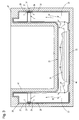
- Such a hollow body is exemplified in Fig. 3 as a thermal container 20 formed and shown in Figure 3 in vertical section.
- This thermal container 20 is in the present embodiment from a first, inner shell body 21 and a second outer shell body 22. These two shell bodies 21 and 22 together form in the assembled state according to FIG 3 shows a trough-like receptacle.
- Such thermos as this is shown as an example in Fig. 3 serve for example for the tempered intake of food.
- the two shell bodies 21 and 22 close a cavity 23, which in the finished state with an insulating compound 24, how polyurethane foam is completely filled.
- insulating compound 24 in the state before its expansion shown. This insulating compound expands during the foaming process 24 in the direction of arrows 18 substantially evenly until the cavity 23 is completely filled.
- the two shell bodies are 21 and 22 via the profile bar 1 in connection with each other.
- the two shell bodies 21 and 22 each have one according to the shape of the profile strip 1 from FIG. 1 circumferential end edge 25 or 26, which the respective end portion the vertically extending in the present embodiment Wall sections 27 and 28 of the shell bodies 21 and 22 form.
- the two wall sections 27 and 28 are in alignment with each other and are all around in the two U-shaped profile section 2 and 3 of the profile bar 1 added.
- FIG. 4 shows an enlarged section IV from FIG. 3 which can be seen that the wall section 27 in the profile section 2 and the wall section 28 in the profile section 3 of the Profile bar 1 is inserted.
- the profile bar 1 In this fully assembled in Fig. 4 and the foamed position is the profile bar 1 with its two outer profile legs 4 and 5 even, flat on the respectively assigned outer surface 29 or 30 of the end edges 25 or 26 of the respective shell body 21 or 22. Due to the dimensionally stable design of both the profile strip 1 as well as the shell body 21 and 22 is between these profile legs 4, 5 and the central web 8 of the profile strip 1 and the recorded end edges 25 and 26 of the two shell bodies 21 and 22 a kind of capillary gap 31 and 32 are formed.
- the wall sections have 27 and 28 of the shell body 21 and 22 'in the area of their circumferential End edges 25 and 26 each tapered in cross section trained mounting web 33 or 34, with which this completely in the respectively assigned profile section 2 or 3 protrude into the profile bar 1.
- the two inner profile legs 6 and 7 of the profile strip 1 form in the area of these assembly webs 33 and 34 a space 35 and 36, in which at the end of the foaming process provided highly compressed insulating material which, for reasons of clarity, is shown in FIG. 4 is not shown.
- the profile bar 1 Due to the design of the profile bar 1 with its inner Profile legs 6 and 7 with their sloping walls 16 and 17, is between the stepped transition area 37 and 38 of the wall sections 27 and 28 and the inner profile legs 6 and 7 a feed gap 39 is formed through which insulating material from the cavity 23 during the foaming process enters the spaces 35 and 36 and these cavities 35 and 36 completely filled out.
- the end areas of the inner profile legs 6 and 7 each with a parallel to the wall sections 27 and 28 extending extension section 41 or 42 may be provided so that between the assigned Wall sections 27 and 28 and dashed in Fig. 4 shown extension sections 41 and 42 in cross section compared to the respective space 35 or 36 narrower Feed channel 43 and 44 is formed.
- the wall sections 27 and 28 in the area of their end edges 25 and 26 and the profile strip 1 with their inner profile legs 6 and 7 and their outer profile legs 4 and 5 is achieved that after the spaces 35 and 36 filled with the appropriate insulating compound are due to the further reaction of this insulating compound whose fluidity changes and decreases.
- this insulating compound whose fluidity changes and decreases.
- the profile strip 1 for example on the outer Shell body 22 or its end edge 26 punctually through an adhesive bond is fixed to put on top of each other of the two shell bodies 21 and 22 a defined positioning of the end edges 25 and 26 in the profile sections 2 and 3 deliver safely.
- both of these End edges 25 and 26 and the profile strip 1 limited is. It is essential here that these cross-sectional shapes both the profile strip 1 and the end edge 25 and 26 in this regard are designed so that on the one hand, insulating material is safe during the foaming process such as polyurethane foam, in the spaces 35 and 36 can get there, is further compressed and on the ground the decreasing flowability causes a pressure build-up there becomes.
- thermos for transportation and for storing foods such as these used in remote kitchens and the like, by law is required since in the cavity 23 or in the Foam body 24 for hygienic reasons no moisture allowed to penetrate.
- thermal containers as Fig. 3 exemplary only the "tub” is shown, for example “Dishwasher safe", which is due to the design according to the invention can be reached safely.
- the wall sections 27 and 28 do not necessarily have to be run in alignment with each other, but can also have a certain Have inclination to each other. Correspondingly, they are Adapt the shapes of the associated profile strips so that ultimately always in principle the embodiment shown in Fig. 4 Has been reached in some areas.
Landscapes
- Engineering & Computer Science (AREA)
- Physics & Mathematics (AREA)
- Thermal Sciences (AREA)
- Food Science & Technology (AREA)
- Mechanical Engineering (AREA)
- Thermal Insulation (AREA)
- Packages (AREA)
- Refrigerator Housings (AREA)
- Details Of Rigid Or Semi-Rigid Containers (AREA)
Applications Claiming Priority (2)
| Application Number | Priority Date | Filing Date | Title |
|---|---|---|---|
| DE10247884A DE10247884B3 (de) | 2002-10-14 | 2002-10-14 | Hohlkörper, insbesondere Thermobehälter |
| DE10247884 | 2002-10-14 |
Publications (3)
| Publication Number | Publication Date |
|---|---|
| EP1422165A2 true EP1422165A2 (fr) | 2004-05-26 |
| EP1422165A3 EP1422165A3 (fr) | 2004-09-08 |
| EP1422165B1 EP1422165B1 (fr) | 2006-02-15 |
Family
ID=29796643
Family Applications (1)
| Application Number | Title | Priority Date | Filing Date |
|---|---|---|---|
| EP03022758A Expired - Lifetime EP1422165B1 (fr) | 2002-10-14 | 2003-10-10 | Corps creux, en particulier conteneur isolant |
Country Status (3)
| Country | Link |
|---|---|
| EP (1) | EP1422165B1 (fr) |
| AT (1) | ATE317811T1 (fr) |
| DE (2) | DE10247884B3 (fr) |
Cited By (3)
| Publication number | Priority date | Publication date | Assignee | Title |
|---|---|---|---|---|
| EP2071969A3 (fr) * | 2007-12-21 | 2010-04-14 | C&B Finantial LLC | Casque de protection composite et son procédé de fabrication |
| CN111516253A (zh) * | 2015-03-23 | 2020-08-11 | 野醍冷却器有限责任公司 | 在制造绝缘容器中的臭氧粘合工艺 |
| CN113650914A (zh) * | 2021-07-22 | 2021-11-16 | 上海百奥泉国际冷链物流有限公司 | 一种冷链运输箱及其冷链运输方法 |
Families Citing this family (2)
| Publication number | Priority date | Publication date | Assignee | Title |
|---|---|---|---|---|
| US7444700B2 (en) * | 2004-10-21 | 2008-11-04 | Sears Manufacturing Co. | Seat cushion with integral cover attachment |
| USD557561S1 (en) | 2007-02-13 | 2007-12-18 | The Coca-Cola Company | Double-walled container |
Family Cites Families (8)
| Publication number | Priority date | Publication date | Assignee | Title |
|---|---|---|---|---|
| DE7441188U (de) * | 1974-12-11 | 1975-04-10 | Freudenberg Carl Fa | Isolierbehaelter aus geschaeumtem Kunststoff |
| GB8327095D0 (en) * | 1983-10-11 | 1983-11-09 | Cole A C | Milk bottle container |
| DE3537061A1 (de) * | 1985-10-17 | 1987-04-23 | Bosch Siemens Hausgeraete | Gehaeuse, insbes. fuer kuehlgeraete und dgl. |
| DE8810591U1 (de) * | 1988-08-20 | 1988-10-06 | Heinz, Wolfgang, 3411 Sudershausen | Behältnis mit Wärmeisolation |
| DE4133926A1 (de) * | 1991-10-12 | 1993-04-15 | Hans Joachim Wolf | Isolierbehaelter |
| US5787839A (en) * | 1994-07-22 | 1998-08-04 | Magnant; Stephen A. | Multiple compartment travel food container apparatus |
| DE19541412C1 (de) * | 1995-11-07 | 1997-04-03 | Hueck Eduard Gmbh Co Kg | Verfahren zum Herstellen eines wärmegedämmten Verbundprofiles |
| DE20109502U1 (de) * | 2001-06-08 | 2002-01-31 | HITHERMA AG, 78056 Villingen-Schwenningen | Einhand-Verschlusssystem für Behälter mit losem Deckel |
-
2002
- 2002-10-14 DE DE10247884A patent/DE10247884B3/de not_active Expired - Lifetime
-
2003
- 2003-10-10 AT AT03022758T patent/ATE317811T1/de active
- 2003-10-10 EP EP03022758A patent/EP1422165B1/fr not_active Expired - Lifetime
- 2003-10-10 DE DE50302409T patent/DE50302409D1/de not_active Expired - Lifetime
Cited By (3)
| Publication number | Priority date | Publication date | Assignee | Title |
|---|---|---|---|---|
| EP2071969A3 (fr) * | 2007-12-21 | 2010-04-14 | C&B Finantial LLC | Casque de protection composite et son procédé de fabrication |
| CN111516253A (zh) * | 2015-03-23 | 2020-08-11 | 野醍冷却器有限责任公司 | 在制造绝缘容器中的臭氧粘合工艺 |
| CN113650914A (zh) * | 2021-07-22 | 2021-11-16 | 上海百奥泉国际冷链物流有限公司 | 一种冷链运输箱及其冷链运输方法 |
Also Published As
| Publication number | Publication date |
|---|---|
| EP1422165A3 (fr) | 2004-09-08 |
| DE10247884B3 (de) | 2004-01-29 |
| DE50302409D1 (de) | 2006-04-20 |
| EP1422165B1 (fr) | 2006-02-15 |
| ATE317811T1 (de) | 2006-03-15 |
Similar Documents
| Publication | Publication Date | Title |
|---|---|---|
| DE102015107121B4 (de) | Verfahren und Vorrichtung zum Verbinden von Profilteilen | |
| DE102007032885A1 (de) | Paneel, insbesondere Bodenpaneel und Einrichtung zum Verriegeln miteinander verbundener Paneele | |
| DE19721478A1 (de) | Druckfügeverfahren und damit hergestellte Rahmen | |
| DE4004332A1 (de) | Ausgeschaeumtes schubladenwand-hohlkammerprofil und verfahren zu seiner herstellung | |
| DE10247884B3 (de) | Hohlkörper, insbesondere Thermobehälter | |
| DE19748613C1 (de) | Verbindungselement für Rahmenprofile | |
| DE2613402A1 (de) | Tuer- oder fensterrahmen aus kunststoff sowie verfahren zu seiner herstellung | |
| DE102008006696B4 (de) | Thermo-Behälter mit thermischer Isolierung von Waren für Transport und Lagerung | |
| EP3339006A1 (fr) | Procédé et dispositif de raccordement des pièces profilées en matière plastique | |
| DE202010003895U1 (de) | Werkzeugkomponente für ein Blasformwerkzeug | |
| DE102010060810A1 (de) | Modular aufgebauter Flaschenkasten aus Kunststoff | |
| DE2348607C2 (de) | Thermoschweißverfahren zum stirnseitigen Verbinden zweier Kunststoffwände | |
| DE2130495C3 (de) | Verfahren zum Herstellen eines ausgeschäumten Rahmenhohlprofils für Rahmen von Fenstern, Türen od.dgl. sowie nach dem Verfahren hergestelltes Rahmenhohlprofil | |
| DE102017131280A1 (de) | Verfahren zum Herstellen eines Formteils sowie Speisereinsatz zur Verwendung in einem solchen Verfahren | |
| DE20215785U1 (de) | Hohlkörper, insbesondere Thermobehälter | |
| DE2226445A1 (de) | Verfahren zum verbinden zweier metallprofile zu einem waermeisolierenden verbundprofil, vorrichtung zur durchfuehrung des verfahrens und verbundprofil | |
| DE2821133B1 (de) | Verfahren zum Verbinden der Enden von auf Gehrung geschnittenen Hohlprofilen | |
| WO2022135760A1 (fr) | Composant, en particulier pour un ressort pneumatique, jambe de force à ressort pneumatique, amortisseur à ressort pneumatique ou boîtier à montage par le dessus, et procédé de fabrication du composant | |
| EP2792446B1 (fr) | Liaison à profil creux utilisant le procédé de soudage par friction-malaxage | |
| DE102013008088B4 (de) | Verfahren zur Herstellung einer Spritzenkartusche mit einem flexiblen Innenbeutel | |
| DE10338109A1 (de) | Verbundbauteil und Verfahren zu dessen Herstellung | |
| DE29506746U1 (de) | Verbindung für Hohlprofilleisten und hierfür verwendbarer Geradverbinder | |
| CH693027A5 (de) | Verfahren zur Herstellung einer Mehrkammer-Verpackungstube. | |
| DE3801568A1 (de) | Tor- oder tuerblattfluegel | |
| DE2353684A1 (de) | Eckverbindung zwischen plattenfoermigen teilen aus holzwerkstoffen |
Legal Events
| Date | Code | Title | Description |
|---|---|---|---|
| PUAI | Public reference made under article 153(3) epc to a published international application that has entered the european phase |
Free format text: ORIGINAL CODE: 0009012 |
|
| AK | Designated contracting states |
Kind code of ref document: A2 Designated state(s): AT BE BG CH CY CZ DE DK EE ES FI FR GB GR HU IE IT LI LU MC NL PT RO SE SI SK TR |
|
| AX | Request for extension of the european patent |
Extension state: AL LT LV MK |
|
| PUAL | Search report despatched |
Free format text: ORIGINAL CODE: 0009013 |
|
| AK | Designated contracting states |
Kind code of ref document: A3 Designated state(s): AT BE BG CH CY CZ DE DK EE ES FI FR GB GR HU IE IT LI LU MC NL PT RO SE SI SK TR |
|
| AX | Request for extension of the european patent |
Extension state: AL LT LV MK |
|
| RIC1 | Information provided on ipc code assigned before grant |
Ipc: 7B 29C 44/18 B Ipc: 7A 47J 41/00 B Ipc: 7B 65D 81/38 A |
|
| 17P | Request for examination filed |
Effective date: 20050304 |
|
| AKX | Designation fees paid |
Designated state(s): AT BE BG CH CY CZ DE DK EE ES FI FR GB GR HU IE IT LI LU MC NL PT RO SE SI SK TR |
|
| GRAP | Despatch of communication of intention to grant a patent |
Free format text: ORIGINAL CODE: EPIDOSNIGR1 |
|
| GRAS | Grant fee paid |
Free format text: ORIGINAL CODE: EPIDOSNIGR3 |
|
| GRAA | (expected) grant |
Free format text: ORIGINAL CODE: 0009210 |
|
| RIN1 | Information on inventor provided before grant (corrected) |
Inventor name: SCHOELLHORN, MARCELLUS Inventor name: HUBER, ERICH |
|
| AK | Designated contracting states |
Kind code of ref document: B1 Designated state(s): AT BE BG CH CY CZ DE DK EE ES FI FR GB GR HU IE IT LI LU MC NL PT RO SE SI SK TR |
|
| PG25 | Lapsed in a contracting state [announced via postgrant information from national office to epo] |
Ref country code: IT Free format text: LAPSE BECAUSE OF FAILURE TO SUBMIT A TRANSLATION OF THE DESCRIPTION OR TO PAY THE FEE WITHIN THE PRESCRIBED TIME-LIMIT;WARNING: LAPSES OF ITALIAN PATENTS WITH EFFECTIVE DATE BEFORE 2007 MAY HAVE OCCURRED AT ANY TIME BEFORE 2007. THE CORRECT EFFECTIVE DATE MAY BE DIFFERENT FROM THE ONE RECORDED. Effective date: 20060215 Ref country code: IE Free format text: LAPSE BECAUSE OF FAILURE TO SUBMIT A TRANSLATION OF THE DESCRIPTION OR TO PAY THE FEE WITHIN THE PRESCRIBED TIME-LIMIT Effective date: 20060215 Ref country code: NL Free format text: LAPSE BECAUSE OF FAILURE TO SUBMIT A TRANSLATION OF THE DESCRIPTION OR TO PAY THE FEE WITHIN THE PRESCRIBED TIME-LIMIT Effective date: 20060215 Ref country code: RO Free format text: LAPSE BECAUSE OF FAILURE TO SUBMIT A TRANSLATION OF THE DESCRIPTION OR TO PAY THE FEE WITHIN THE PRESCRIBED TIME-LIMIT Effective date: 20060215 Ref country code: SI Free format text: LAPSE BECAUSE OF FAILURE TO SUBMIT A TRANSLATION OF THE DESCRIPTION OR TO PAY THE FEE WITHIN THE PRESCRIBED TIME-LIMIT Effective date: 20060215 Ref country code: FI Free format text: LAPSE BECAUSE OF FAILURE TO SUBMIT A TRANSLATION OF THE DESCRIPTION OR TO PAY THE FEE WITHIN THE PRESCRIBED TIME-LIMIT Effective date: 20060215 Ref country code: GB Free format text: LAPSE BECAUSE OF FAILURE TO SUBMIT A TRANSLATION OF THE DESCRIPTION OR TO PAY THE FEE WITHIN THE PRESCRIBED TIME-LIMIT Effective date: 20060215 Ref country code: SK Free format text: LAPSE BECAUSE OF FAILURE TO SUBMIT A TRANSLATION OF THE DESCRIPTION OR TO PAY THE FEE WITHIN THE PRESCRIBED TIME-LIMIT Effective date: 20060215 |
|
| REG | Reference to a national code |
Ref country code: CH Ref legal event code: EP Ref country code: GB Ref legal event code: FG4D Free format text: NOT ENGLISH |
|
| REG | Reference to a national code |
Ref country code: IE Ref legal event code: FG4D Free format text: LANGUAGE OF EP DOCUMENT: GERMAN |
|
| REF | Corresponds to: |
Ref document number: 50302409 Country of ref document: DE Date of ref document: 20060420 Kind code of ref document: P |
|
| PG25 | Lapsed in a contracting state [announced via postgrant information from national office to epo] |
Ref country code: BG Free format text: LAPSE BECAUSE OF FAILURE TO SUBMIT A TRANSLATION OF THE DESCRIPTION OR TO PAY THE FEE WITHIN THE PRESCRIBED TIME-LIMIT Effective date: 20060515 Ref country code: DK Free format text: LAPSE BECAUSE OF FAILURE TO SUBMIT A TRANSLATION OF THE DESCRIPTION OR TO PAY THE FEE WITHIN THE PRESCRIBED TIME-LIMIT Effective date: 20060515 Ref country code: SE Free format text: LAPSE BECAUSE OF FAILURE TO SUBMIT A TRANSLATION OF THE DESCRIPTION OR TO PAY THE FEE WITHIN THE PRESCRIBED TIME-LIMIT Effective date: 20060515 |
|
| PG25 | Lapsed in a contracting state [announced via postgrant information from national office to epo] |
Ref country code: ES Free format text: LAPSE BECAUSE OF FAILURE TO SUBMIT A TRANSLATION OF THE DESCRIPTION OR TO PAY THE FEE WITHIN THE PRESCRIBED TIME-LIMIT Effective date: 20060526 |
|
| REG | Reference to a national code |
Ref country code: CH Ref legal event code: NV Representative=s name: BRAUNPAT BRAUN EDER AG |
|
| PG25 | Lapsed in a contracting state [announced via postgrant information from national office to epo] |
Ref country code: PT Free format text: LAPSE BECAUSE OF FAILURE TO SUBMIT A TRANSLATION OF THE DESCRIPTION OR TO PAY THE FEE WITHIN THE PRESCRIBED TIME-LIMIT Effective date: 20060717 |
|
| NLV1 | Nl: lapsed or annulled due to failure to fulfill the requirements of art. 29p and 29m of the patents act | ||
| GBV | Gb: ep patent (uk) treated as always having been void in accordance with gb section 77(7)/1977 [no translation filed] |
Effective date: 20060215 |
|
| REG | Reference to a national code |
Ref country code: IE Ref legal event code: FD4D |
|
| PG25 | Lapsed in a contracting state [announced via postgrant information from national office to epo] |
Ref country code: MC Free format text: LAPSE BECAUSE OF NON-PAYMENT OF DUE FEES Effective date: 20061031 |
|
| PLBE | No opposition filed within time limit |
Free format text: ORIGINAL CODE: 0009261 |
|
| STAA | Information on the status of an ep patent application or granted ep patent |
Free format text: STATUS: NO OPPOSITION FILED WITHIN TIME LIMIT |
|
| 26N | No opposition filed |
Effective date: 20061116 |
|
| EN | Fr: translation not filed | ||
| BERE | Be: lapsed |
Owner name: HUBER, ERICH Effective date: 20061031 Owner name: SCHOLLHORN, MARCELLUS Effective date: 20061031 |
|
| PG25 | Lapsed in a contracting state [announced via postgrant information from national office to epo] |
Ref country code: FR Free format text: LAPSE BECAUSE OF FAILURE TO SUBMIT A TRANSLATION OF THE DESCRIPTION OR TO PAY THE FEE WITHIN THE PRESCRIBED TIME-LIMIT Effective date: 20070105 |
|
| PG25 | Lapsed in a contracting state [announced via postgrant information from national office to epo] |
Ref country code: CZ Free format text: LAPSE BECAUSE OF FAILURE TO SUBMIT A TRANSLATION OF THE DESCRIPTION OR TO PAY THE FEE WITHIN THE PRESCRIBED TIME-LIMIT Effective date: 20060215 Ref country code: GR Free format text: LAPSE BECAUSE OF FAILURE TO SUBMIT A TRANSLATION OF THE DESCRIPTION OR TO PAY THE FEE WITHIN THE PRESCRIBED TIME-LIMIT Effective date: 20060516 |
|
| PG25 | Lapsed in a contracting state [announced via postgrant information from national office to epo] |
Ref country code: EE Free format text: LAPSE BECAUSE OF FAILURE TO SUBMIT A TRANSLATION OF THE DESCRIPTION OR TO PAY THE FEE WITHIN THE PRESCRIBED TIME-LIMIT Effective date: 20060215 |
|
| PG25 | Lapsed in a contracting state [announced via postgrant information from national office to epo] |
Ref country code: TR Free format text: LAPSE BECAUSE OF FAILURE TO SUBMIT A TRANSLATION OF THE DESCRIPTION OR TO PAY THE FEE WITHIN THE PRESCRIBED TIME-LIMIT Effective date: 20060215 Ref country code: LU Free format text: LAPSE BECAUSE OF NON-PAYMENT OF DUE FEES Effective date: 20061010 Ref country code: HU Free format text: LAPSE BECAUSE OF FAILURE TO SUBMIT A TRANSLATION OF THE DESCRIPTION OR TO PAY THE FEE WITHIN THE PRESCRIBED TIME-LIMIT Effective date: 20060816 |
|
| PG25 | Lapsed in a contracting state [announced via postgrant information from national office to epo] |
Ref country code: FR Free format text: LAPSE BECAUSE OF FAILURE TO SUBMIT A TRANSLATION OF THE DESCRIPTION OR TO PAY THE FEE WITHIN THE PRESCRIBED TIME-LIMIT Effective date: 20060215 Ref country code: CY Free format text: LAPSE BECAUSE OF FAILURE TO SUBMIT A TRANSLATION OF THE DESCRIPTION OR TO PAY THE FEE WITHIN THE PRESCRIBED TIME-LIMIT Effective date: 20060215 |
|
| PG25 | Lapsed in a contracting state [announced via postgrant information from national office to epo] |
Ref country code: BE Free format text: LAPSE BECAUSE OF FAILURE TO SUBMIT A TRANSLATION OF THE DESCRIPTION OR TO PAY THE FEE WITHIN THE PRESCRIBED TIME-LIMIT Effective date: 20061031 |
|
| PGFP | Annual fee paid to national office [announced via postgrant information from national office to epo] |
Ref country code: AT Payment date: 20101028 Year of fee payment: 8 |
|
| PGFP | Annual fee paid to national office [announced via postgrant information from national office to epo] |
Ref country code: CH Payment date: 20101029 Year of fee payment: 8 Ref country code: DE Payment date: 20101007 Year of fee payment: 8 |
|
| REG | Reference to a national code |
Ref country code: CH Ref legal event code: PL |
|
| PG25 | Lapsed in a contracting state [announced via postgrant information from national office to epo] |
Ref country code: LI Free format text: LAPSE BECAUSE OF NON-PAYMENT OF DUE FEES Effective date: 20111031 Ref country code: CH Free format text: LAPSE BECAUSE OF NON-PAYMENT OF DUE FEES Effective date: 20111031 Ref country code: DE Free format text: LAPSE BECAUSE OF NON-PAYMENT OF DUE FEES Effective date: 20120501 |
|
| REG | Reference to a national code |
Ref country code: DE Ref legal event code: R119 Ref document number: 50302409 Country of ref document: DE Effective date: 20120501 |
|
| REG | Reference to a national code |
Ref country code: AT Ref legal event code: MM01 Ref document number: 317811 Country of ref document: AT Kind code of ref document: T Effective date: 20111010 |
|
| PG25 | Lapsed in a contracting state [announced via postgrant information from national office to epo] |
Ref country code: AT Free format text: LAPSE BECAUSE OF NON-PAYMENT OF DUE FEES Effective date: 20111010 |